I've started a Leeuwenhoek microscope project. There have been many replicas made by others, but this one will be mine. 🙂
Leeuwenhoek did not exactly invent the microscope, but he is famous for the many original findings made via his instruments, enabled by his secret method of making superior lenses – a secret he took to the grave.
His instruments contained a single lens element of high power. They were originally thought to be tiny glass beads (spherical lenses), but some recent examinations suggests some or all were bi-convex in shape.
Instead of blowing or grinding a lens, I simply purchased one. It's a tiny 2-element optically-coated achromatic lens that is 3mm in diameter by 3mm thick, and with a 4.5mm focal length. This makes it very high powered at 222 diopters (a typical magnifying glass is 4 diopters), and is in the neighborhood of Leeuwenhoek's various iterations.
An achromatic lens is typically made from two different glasses (classically, "crown" and "flint" glass), usually cemented together, such that the two glasses partially cancel out chromatic aberration. This lens also has a magnesium-flouride anti-reflective coating. (It was not cheap!)
Using a 2-element coated achromatic lens is an unfair advantage, since achromats and optical coatings were hundreds of years into the future for Leeuwenhoek. But if he had these technologies available, he certainly would have used them!
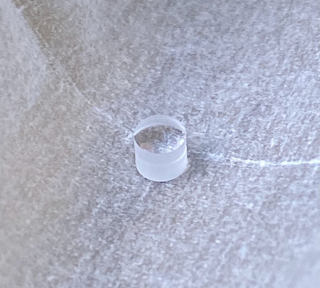
Here's a picture of the lens. You can see where the two elements join.
I temporarily mounted it and managed to view things through it, and I have to say it's quite difficult to use, especially due to the very shallow eye relief. In retrospect, perhaps I should have bought a larger-diameter and longer focal length lens. But once you get it right, it provides a surprisingly high quality and highly-magnified image that I'm sure Leeuwenhoek would have enjoyed.
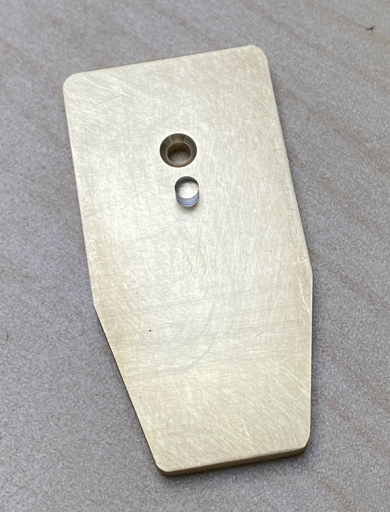
Leeuwenhoek mounted his lens sandwiched between two thin sheets of metal that were then riveted together. I chose to use a solid piece of brass, into which I drilled and reamed a 3mm hole as an exact fit for the lens. This avoids obscuring the lens' periphery. I'm a bit terrified with the idea of using a retaining adhesive on it, though!
As the brass was slightly thicker than the lens, I added a countersink on one side so the lens can sit a tiny bit proud on both sides. That way, the lens can hopefully be kept clean a little easier.
The body of the microscope is paddle shaped, about an inch by two inches. It fits comfortably pressed against your cheek and nose. This is essential, since with such a shallow eye relief you need to brace it steadily lest you poke your eye.
Here's the body in its final shape, with the reamed and countersunk hole for the lens. The lens is sitting on it.
So just a little progress so far in a relatively simple project. Still to be done are to add a translation and focusing mechanism, a clip of some sort for holding the subject, and a handle.
His microscopes used a point to hold the subject. Instead, I'd like to make a holder for microscope cover-slips. I'd also like to improve on his focusing and translation mechanism while retaining the spirit of his approach. If I fail at that, I'll just do it Leeuwenhoek's original way. After all, he reportedly made well over 400 microscopes(!), so he likely went through many ideas.
Interesting. Optics is a field unknown to me – I have a 'few' boxes of old binoculars, microscopes of various types, inspection scopes, cameras, video-cams, etc, and have often desired to build 'something' from all the lenses, but know too little!
SK beautiful. My only concern would be that you mention a reamed hole and brass as the lens holder. brass has a high expansion and may move and damage the lens ? Noel.
Thanks for providing links to originals and other replicas. One link mentioned how notoriously difficult his microscopes were to use, and I'm finding that myself, too!
High-quality achromats like the one I'm using are for general scientific use, with no one special purpose in mind. But if you have seen pictures of optical tables with lasers shooting around everywhere, that's one application for them. They are available in a very wide range of diameters and focal lengths. You can also get them with other coatings for better transmission in the ultra-violet, and so on (magnesium flouride coatings are only good for visual light). Very tiny lenses like this one are more expensive than average. This was bought from Edmund Optics and cost a little over $100, while an uncoated single-element lens could be had for pennies.
An interesting point is that, back in Leeuwenhoek's day, his single high-powered lens approach (essentially an extremely powerful magnifying glass) was more successful than compound microscopes were. A compound microscope includes an objective and an eyepiece, which when combined multiplies the power (total power = objective power x eyepiece power). However, optical aberrations were pretty bad back then, and in compound form the net result of multiplying those aberrations was simply worse than the best single lens. It wasn't until the invention of achromatic lenses (like I'm using here) that compound microscopes became practical.
The periphery of Leeuwenhoek's lenses were blocked from use by the frame they were mounted in. Whether he understood this or not, that's equivalent to "stopping down" – constricting the aperture of the lens. Aberrations from the periphery of a lens are typically far worse than in the center, and stopping down blocks the worst of that. But my lens is quite high quality and should be good out to its edge, and so I wanted to leave the entire lens surface clear, hence the reamed hole. The fit I have is a close sliding one, with just a tiny bit of binding. But I hadn't considered thermal expansion. I guess I'll just take my chances with that.
My understanding is the Leeuwenhoek lens was spherical, as near as nature could make them. One option is a drop of water, which surface tension pulls into a sphere. Another is to pour molten soda glass through a sieve into water from a good height inside a shot-tower. On the way down surface tension forms the liquid glass into a solid spherical drop, quite small as in SK's example. The trick is getting the temperature and height just right so the drops are clear, and the right size and shape. Relatively few were fit for purpose, and Leeuwenhoek and his successors sorted them manually with many rejects.
Water works well as a lens but not for long – it evaporates. Well formed glass spheres are better. Main problem is the eye has to be brought very close to the lens to focus it, making the microscope tiring to use. Compound microscopes are a lot friendlier, but their optics and mechanics are high-tech.
One of the two lenses – the lower power of the two – is "lentil" shaped (more or less like a standard bi-convex lens), and one is a sphere. The spherical one also has a little stem, presumably left over from the lens-making process, e.g. a stem on the end of which a spherical drop was formed.
In one of his letters, Leeuwenhoek stated that he ground his lenses, and at other times he derided spherical ones (he was in competition with Hooke at the time, who used them), but apparently he used them too in at least some of his microscopes.
You should join the Royal Microscopical Society. No, it's not a very small society, it is devoted to furthering the science of microscopy. http://www.rms.org.uk
I did my PhD in the field of microscopy and became familar with light, confocal and ultra-thin section immuno-gold electron microscopy. Our department had a replica Leeuwenhoek which I played with a few times and found virtually impossible to use. I think Leeuwenhoek must have had a lot of patience….
Model engineers may be interested in the cutting of ultra-thin frozen sections. The microtome (we used a Reichert Cryo Ultramicrotome) could cut sections down to 5nm thick. Back in the day, these were purely mechanical devices that advanced the block (the sample) by increments of as little as 5nm relative to the diamond knife. All this while the sample was held at liquid nitrogen temperatures. Pause to think about that for a minute…..
Whilst not wishing to hi-jack the thread … this seems a good place to mention that the exhibition that accompanies the mmc is free to attend, and there is still time to register:
I've been thinking about the focusing mechanism. I'm not trying to make a strict replica. Rather, I'm trying to incorporate a few improvements while maintaining the readily-identifiable appearance of being a "Leeuwenhoek microscope."
For one, I've been intending to use a small round piece of glass as a slide on which to mount a subject rather than the needle that Leeuwenhoek used. This would require some sort of holder that I haven't fully figured out yet.
On to the focusing mechanism: Leeuwenhoek used a screw (the focusing screw that sticks outward from the back) that applied a force to pry the entire assembly apart, thereby adjusting the distance from the lens to the subject. This has several issues and side effects that I'd like to improve on. For one, this bending changes the plane on which the subject is in, tilting it forward or backward relative to the lens. It also slightly shifts and rotates the subject. And then of course there's the bending itself, which I'd prefer to avoid entirely if possible.
I can imagine a few ways to focus while maintaining parallelism of the slide, but so far my ideas tend to be either complicated or difficult to miniaturize.
Any brilliant ideas from the readers?
Hehe, it would be better if I figured it all out in CAD before even starting, right? But too late for that now! Onward! 🙂
I can imagine a few ways to focus while maintaining parallelism of the slide, but so far my ideas tend to be either complicated or difficult to miniaturize.
Any brilliant ideas from the readers?
.
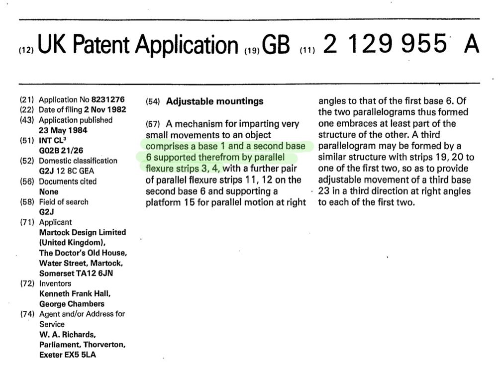
I would first consider using a pair of parallel flexures
… but if you are prepared to stray a long way from the original, there’s always piezo actuators
The world of electron microscopy is fairly small and I wonder if our paths ever crossed? I was head of the electron microscope unit at Southampton General Hospital from the mid 1960’s until 1987. Then senior lecturer in electron microscopy and cellular pathology at the University of the West of England in Bristol from 1987 to 2000. Also a model engineer for most of the time. As you imply, the mechanics of electron microscopy and associated specimen preparation are mind boggling.
Your microscope project looks interesting. Good luck with it.
Apologies to other participants in this thread for going off piste.
We may well have met. I entered medical school in Southampton in 1984, then did research in Cambridge in the 90s. I am now a consultant nephrologist so not doing any microscopy anymore, but we do get EM done on all our renal biospies…..
I'm looking forward to seeing this project progressing.
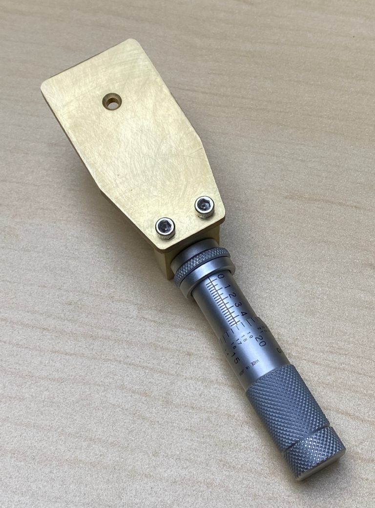
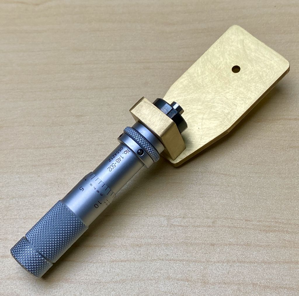
I had a small 1/2" micrometer head in my drawer, and thought it would be a perfect addition. I'd like the micrometer to perform focusing rather than vertical translation as in the original. It may be sacrilege, but I think it works! 😀
The front, facing towards your eye:
And the back, facing away:
I will explore some sort of flexure for focusing, but I think I'll do that in 3-D printed form, at least at first.
In my drawer I had a smaller micrometer head that's found its way on to the opto sensor platform on the latest clock.
It adjusts the lateral sensor position. It came from my dad's come in handy collection of bits he salvaged when the electron microscope company he worked for closed down.
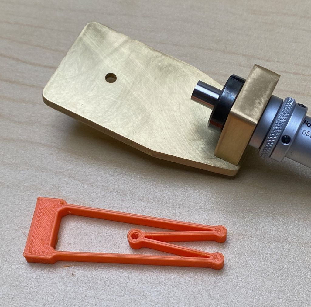
I printed a primitive flexure as a test. It wasn't printed to proper scale or with any real thought.
It certainly is flexy, but I'm not very happy with how it moves. It's actually too flexible and I think it would have to be stiffened a fair amount. It's printed in PETG, which I use for pretty much everything. Maybe PLA would be better.
It's also becoming clear that miniaturizing an entire table that moves properly on flexures will not be easy. I might abandon this approach and go with a much simpler hinge-type mount. That has the disadvantage of tilting forward or backward out of the plane of the lens as it's focused (as Leeuwenhouk's did), but it may suffice.
I also ordered a few 10mm diameter, 1.1mm thick borosilicate glass windows (uncoated) to use as subject slides. When I was a kid, I built crazy things out of bent nails and scraps of wood, and proper materials were simply unavailable. It's so awesome to now be able to order exotic materials with a click of a button!
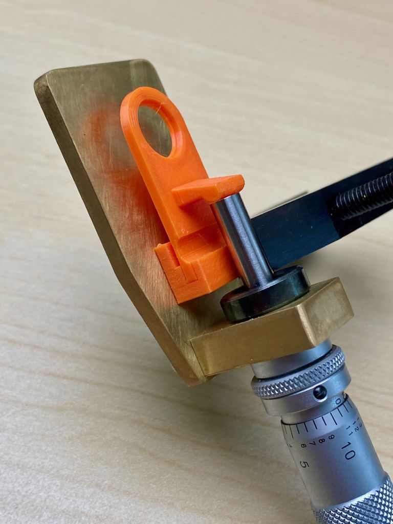
I printed out a hinged stage to see how well that might work, and it works pretty well. It's just clamped in place so I could test its behavior.
It's a simple technique, though it has the disadvantage of losing parallelism to the lens while focusing (the original had the same problem).
The translation ratio (stage movement / micrometer movement) is a little below 1:1 at the lens, so a small reduction, which is fine – I wanted to avoid amplifying the micrometer's motion.
I think the right strategy would be to position the stage tilted slightly up (higher) than the nominal focus point when no micrometer pressure is applied, but such that the stage is flat when the micrometer moves it to the nominal focus point.
One of the goals of this project is to gain some experience with machining, so I'd like to do this in brass, too. But the prints are very helpful to test ideas and work things out, including the important task of calibrating the point of focus.
A tidy little hinge, which I suppose can be categorised as a ‘bell crank lever’
Incidentally: I must admit to being surprised by your 3D printed interpretation of the flexure mechanism … because what I had in mind was two pieces of shim-stock separated by a spacer at each end.