A fishy story

Advert

A fishy story

Viewing 14 posts - 26 through 39 (of 39 total)
  • Author
    Posts
  • #156943
    Russell Eberhardt
    Participant
      @russelleberhardt48058

      Why not buy the correct line from the horological supplier I suggested? They supply gut, synthetic gut, steel, and phosphor bronze line for fusee use. At under £4 it's not worth risking anything else.

      Russell.

      Advert
      #156944
      Russell Eberhardt
      Participant
        @russelleberhardt48058

        Posted by Howard Winwood on 03/07/2014 12:09:55:

        as for creep, if initially stretched to 100 lb future stretch is negligible. it is important that bow strings do not stretch after an initial shoot in period, even more so with compound bows.

        Agreed, also important for my Japanese kyudo bow and it hurts like **** when it breaks – we don't wear any of those sissy wrist guardswink

        Russell.

        #156992
        Sam Stones
        Participant
          @samstones42903

          Gentlemen,

          Thanks to all of you.

          This veritable feast of advice leaves me gobsmacked.

          Speaking of which, there’s now lots of egg on my gob. Fellow Victorian, John, was right in pointing out that I have been `attacked by the creep gremlin’. How could it be that I went ahead ignoring the creep characteristics of plastic fishing line while having sufficient knowledge about viscoelastic behaviour, especially of polyolefins and engineering polymers? I was even working in a plastics laboratory where the very 1000 hour creep tests were being conducted. The resultant curves became the very source of many of my designs. A maximum strain of 1% was my design benchmark, mostly relating to compressive and buckling phenomena.

          How was it that I had a fixation about ultraviolet degradation? Well, it is Australia, and several of the plastics components which make up our north-facing vertical blinds have suffered from direct sunlight.

          Wake up Sam!

          OK! Humble pie eaten.

          At 79, this will definitely be my last chance at fixing the problem. I’m now fully convinced that I need to switch to multi-strand metal coated or uncoated line, and as I’ve mentioned earlier my choice of terminations needs to be resolved. I am impressed by the sample line I was given, and expect that a simple loop crimped with a copper ferrule would be the way to go. This seems to be a common method amongst fishing experts. Unlike my failed method, hiding the terminations will no longer be an option. This afternoon, I’ll make another visit to Tackle World.

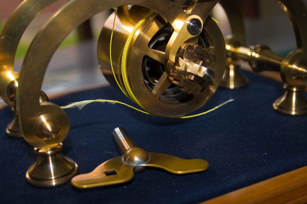
          For the time being and to bring this up to date, I found that the line had thinned. This wasn’t all that obvious until I got down to taking the photograph. For the record, the thinned thread came from close to the break, and was subjected to the greatest tensile stress, whereas the thread below it came from near the fusee termination.

          crw_6344---comparison-of-stretched-and-unstretched-cord---04-07-14.jpg


          For the record, here's a picture of how I found the clock (and fusee line), after it stopped.

          crw_6341---the-broken-cord---26-06-14.jpg

          The badly frayed end must have received some bashing during the very rapid unwinding of the spring.

          Thanks again to every contributor. It's been a lesson for me, I trust that it adds to the collective experience for model engineers everywhere.

          I'll be back.

          Regards,

          Sam

          Edited By Sam Stones on 04/07/2014 01:16:47

          #157106
          John Olsen
          Participant
            @johnolsen79199

            Didn't they have something like this happen to the Westminster Clock once? I think in that case it was a shaft failing, and the resulting damage at first was suspected to be from an IRA bomb.

            I used to have an old Venner time switch with a fusee mechanism. That used a very fine chain rather than a wire. Like a bicycle chain, but only about 1mm wide.

            John

            #157136
            Russell Eberhardt
            Participant
              @russelleberhardt48058

              Posted by John Olsen on 05/07/2014 09:13:12:

              I used to have an old Venner time switch with a fusee mechanism. That used a very fine chain rather than a wire. Like a bicycle chain, but only about 1mm wide.

              Yes, also used in precision chronometers. It is still made but not cheap!

              Russell.

              #157482
              Sam Stones
              Participant
                @samstones42903

                Gentlemen,

                I'm back with a (sort of) conclusion.

                How much nicer it would look with a chain drive – but not for me.

                However, following the failure of the fishing line which transfers the oomph from the main-spring barrel to the fusee, and with the gift of hindsight I decided to check a few facts.

                And, I still have egg on my face over the aspects of creep.

                With great respect for the late Mr Stevens, the following details may also offer reasons (in my situation), why I had a fixation on fishing line, and why any serious modifications (to my fusee) are now prohibitive.

                It is worth noting here that I machined the fusee back in the early 70’s, not long after Mr Stevens’ article was published, and (as I’ve mentioned too many times already), I no longer have a workshop.

                In his article commencing in February 1972, especially (Vol 138 Issues 3334 and 3435, Pages 139, 140, 168, and 169 of Model Engineer), Mr Stevens provided information (and dimensions) of:-

                • The fusee and the barrel – [page 139];
                • A recess in the edge of the barrel for the knot of a Nylon fishing line – [page 140];
                • An improvised fusee cutter – [page 168];
                • The 0.035” wide bull-nosed cutter for machining the fusee groove – [page 168];
                • A recess in the fusee for the knot in a Nylon washing line – [page 169].

                Incidentally, the space in the fusee recess is swept by the fusee ratchet mechanism during winding, so anything protruding (eg. a knot) is likely to interfere with the winding process.

                It wasn’t necessary for me to build the fusee cutter. I simply set up my Myford ML7 to machine the spiral groove using the same template I had used to `swing’ the basic profile (a 2” radius). Using a cam follower principle between the cross-slide and the machine bed, the depth of cut was adjusted through the top slide. I’m no stranger to the intricacies of screw cutting, so this exercise was hardly challenging.

                On page 140, Mr Stevens then goes on to say;

                A key-hole slot is made near the front edge of the barrel tube and a crescent filed on the cover immediately beneath. This is to take a Nylon fishing line which serves admirably in place of the traditional gut.

                On page 169 Mr Stevens then goes on to say;

                “A hole about 3/64 in. dia. [about 1.2 mm], is next drilled from the outside [of the fusee] into this recess which is to secure the nylon line, and a space for the knot milled out. (The nylon cord is obtained in the guise of a domestic washing line from any hardware shop!).”

                So I now realise that as an amateur clock-maker, that’s where my fixation for fishing line came from.

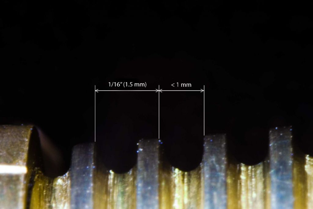
                This photograph taken at the small end, is a rather `fuzzy fusee’ profile of the spiral groove as it currently appears. A 1 mm drill doesn’t quite fit, so it looks like I was fairly close to drawing.

                crw_6354---fusee-profile---06-07-14.jpg

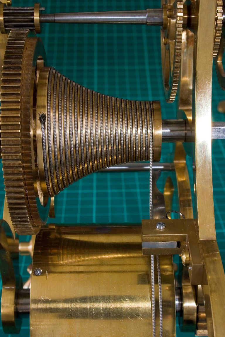
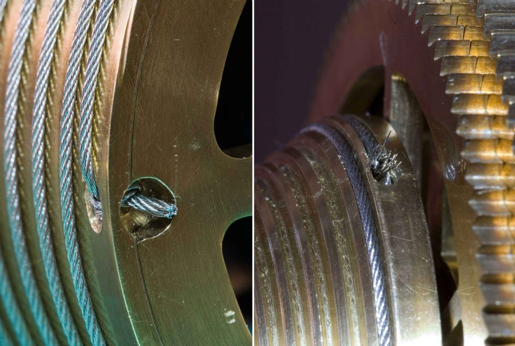
                In conclusion, despite a fixation on using a synthetic cord (fishing line), I eventually accepted the advice of a professional clock-maker and used multi strand steel.

                See this second picture.

                crw_6364---fishing-line-replaced-with-steel---09-07-14.jpg

                I’m not too impressed with the tail ends of the knots. My original method hid the line terminations.

                As if all this wasn’t enough, I suddenly noticed in the very top LH corner of this picture that one of the pins in the first lantern pinion had worked loose. Oh dear! Or words to that effect.

                Edited By Sam Stones on 10/07/2014 02:30:17

                #157483
                John McNamara
                Participant
                  @johnmcnamara74883

                  I rather like the contrast of the steel on the brass Sam.

                  Your work is exceptional….

                  Regards
                  John

                  #157484
                  Sam Stones
                  Participant
                    @samstones42903

                    John,

                    As always, you are very kind.

                    Although I had grown to like the yellow of the fishing line, I rather like the steel wire now.

                    By the way, I cleaned the clock and the chaps at the clock shop who supplied the wire, also pulled the main-spring out of the barrel for me. After I cleaned it, they put it back adding some special oil before they did. When I wound the clock, the extent of the swing of the balance wheel was most impressive.

                    I've not yet had a chance to adjust the beat, but overnight it had gained ten seconds, whereas before, it was all over the place.

                    Thanks again to everyone.

                    Sam

                    Edited By Sam Stones on 10/07/2014 03:38:17

                    #157486
                    Muzzer
                    Participant
                      @muzzer

                      You can get cable ties in natural (uncoloured) Nylon or black (and other colours). If you use the natural ones in a situation where they are exposed to daylight, they soon become very brittle. Which is why natural ones are banned for use in many applications such as automotive.

                      It's possible the outer strands on your clock were becoming brittle, leading to the eventual failure of the bundle. You may not have been completely wrong in suspecting UV?

                      Another material that is easy to source as an alternative to Nylon would be polyester (PET, tyre cord, Terylene, Dacron etc). It is naturally resistant to UV, as you can see from the fact that discarded drinks bottles never seem to degrade, even after years outdoors. But I like the look of the steel!

                      Murray

                      #157491
                      Michael Gilligan
                      Participant
                        @michaelgilligan61133

                        Sam,

                        The steel line looks very good.

                        For next time [just in case there is one], and for the benefit of the rest of us; it may be worth trying an experiment …

                        The traditional way of terminating Bowden Cables was to soft-solder a nipple [which has a generous countersink in the distal end, with the strands of the cable splayed-out into it].

                        This is unlikely to work with Stainless Steel cables, so I think we should try using 638 Loctite as a substitute for the Solder.

                        MichaelG.

                        #157493
                        John McNamara
                        Participant
                          @johnmcnamara74883

                          One little trick that does work if you can find someone with oxy is to melt the end of the cable into a small blob, I don't think it will be big enough on its own to hold on to but it does get rid of the frayed ends. I would hold the cable close to the end in a pair of pliers (Not good pliers just a junk pair I keep for this sort of abuse) That will help reduce discolouration. A second or two in the flame should do it.

                          I used this method on 3mm SS cable stays on a Jig, The cable was clamped but the ends were exposed, and very sharp, It was very easy for an operator to get caught….. Ouch.

                          I wonder thinking along Michael Gilligan's path if you could whip (Wrap) the ends of the cable with fine maybe brass or copper wire then silver solder them. Maybe that would create an end big enough to hold in the keyhole arrangement used in the clock? You could whip more than you need then just grind the end back for a nice finish. It would also allow you to start soldering in the area to be ground away. and watch the solder run up the cable. the silver solder will try to wick itself along the strands so those pliers would be needed to keep the temperature down to stop the wicking where you don't want it.

                          Regards
                          John

                          #157504
                          Gordon W
                          Participant
                            @gordonw

                            I think a suitable brass nipple would work ok, as used on bike cables. The solder does not need to "stick" to the cable, the cable is opened out into the countersink and soft soldered. The solder stops the splayed out ends of the cable from compressing, the nipple can't come off. I would not risk it on a brake cable but sure it will work on this job.

                            #158064
                            Sam Stones
                            Participant
                              @samstones42903

                              Gentlemen,

                              Thank you for your many suggestions.

                              As a postscript to my `Fishy Story’, I can report that with multi-strand stainless steel wire installed between the fusee and the barrel and, after cleaning the pivots and pivot holes, the clock has responded well. If you haven’t been following the dialogue between my various interludes, the clock should run for eight days on one winding. It is no surprise therefore to know that it’s called an eight-day clock.

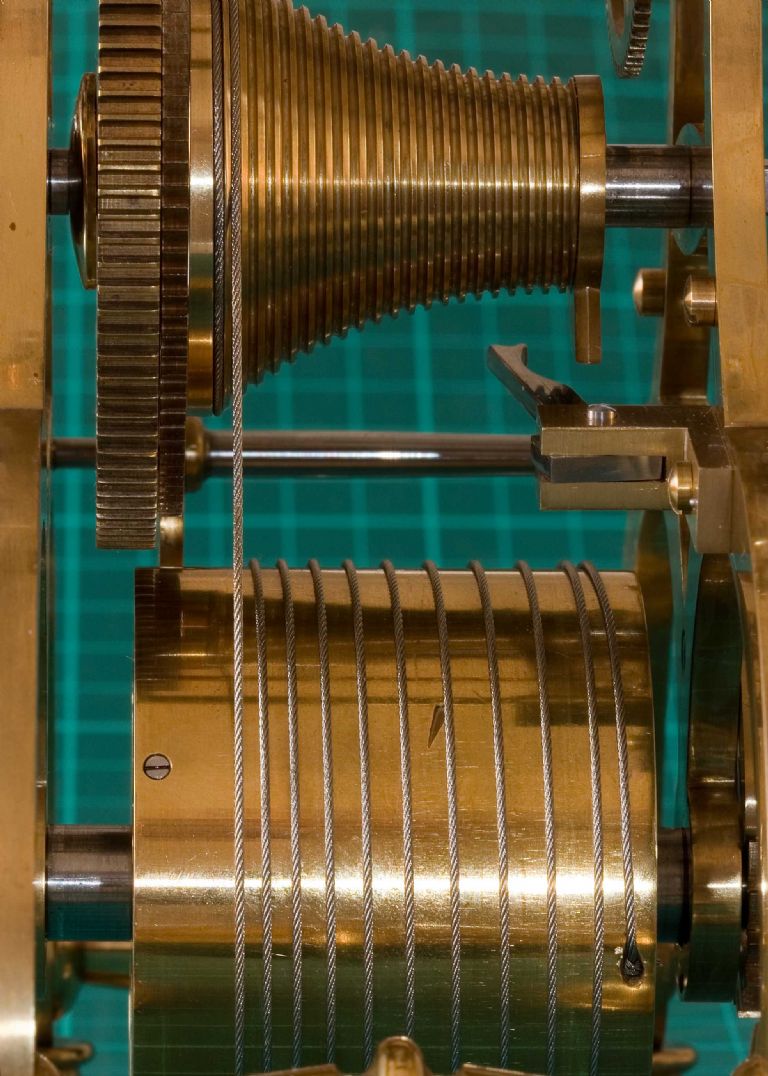
                              For the record, I photographed the fusee and barrel just as the clock was about to stop. You can see how, in running off the fusee, the wire has (neatly) arranged itself around the barrel.

                              Barrel-&-fusee

                              I also photographed the two wire terminations – `Thumb knots’ – for me the simplest way out to a less than ideal solution. Incidentally, this picture also captures (centre right), the stop-work iron and the associated `snail' hook.

                              Both-knots.jpg

                              It looks like my wire cutters missed a few loose ends.

                              The correct way to terminate them is illustrated on page 106 of `Clock and Watch Repairing’ written by Donald De Carle (soft-back edition).

                              The following notes should also serve to highlight the fact (which I discovered some considerable time ago), that the 2” radius of the fusee profile does not accurately compensate for the output of the main spring. To determine the best contour, I should have done some homework back in the 70’s when I first began making the clock.

                              So here is what has happened since I set the clock ticking eight days ago:

                              During the first couple of days, I was pleasantly surprised to find that the clock was holding the time to within just a few seconds per day. Previously, its rate (beat) was all over the place, gaining as much as ten minutes per complete winding. I could never determine the real cause of the variation, and still can’t for that matter. What appeared to be happening was that when the balance wheel appeared to be sluggish, ie . swinging a total of less than 180°, the clock gained. I won’t go into my theory on that score, unless there needs to be some debate.

                              At about day three and still with the balance wheel doing a very lively (and greater than 360°, swing, the clock continued to lose. I felt pleased in some respects that the balance wheel was still romping along. By about day six, the clock had lost almost three minutes. It was then that I noticed that not only was it not losing, it was actually gaining.

                              On the morning of day eight, I waited for the clock to stop. My main purpose was to determine how far the fusee turned before the main spring ran out of puff. When the braided fishing line was doing the work, there could still be at least three full turns of line remaining wrapped around the fusee. More than likely this was signalling that after three years, the clock was in need of cleaning.

                              Shortly before the clock ran out of power, the total balance wheel swing was down to less than 90°, and within the previous twenty-four hours, had gained almost 60 seconds.

                              Over the past four years in particular, the whole process of building this clock has been quite a steep learning curve for me. I could not have got there without the very generous help from everyone who offered help and advice.

                              Good luck, and may none of your projects end up in the scrap bin.

                              Regards,

                              Sam


                              Edited By Sam Stones on 17/07/2014 05:45:15

                              #158065
                              Sam Stones
                              Participant
                                @samstones42903

                                Sorry folks,

                                Where I wrote :-

                                … I also photographed the two wire terminations – `Thumb knots’ – for me the simplest way out to a less than ideal solution. Incidentally, this picture also captures (centre right), the stop-work iron and the associated `snail' hook." …

                                This latter sentence applies to the first photograph.

                                Apologies! crying

                                Edited By Sam Stones on 17/07/2014 05:57:45

                              Viewing 14 posts - 26 through 39 (of 39 total)
                              • Please log in to reply to this topic. Registering is free and easy using the links on the menu at the top of this page.

                              Advert

                              Latest Replies

                              Viewing 25 topics - 1 through 25 (of 25 total)
                              Viewing 25 topics - 1 through 25 (of 25 total)

                              View full reply list.

                              Advert

                              Newsletter Sign-up