Hi John,
Many thanks for your prompt reply. There is certainly no need to apologise. If anything, I must apologise for failing to provide references to previous postings on this subject. A scan of the relevant threads reveals that I spawned (or contributed to), no less than twenty (20) which are either relate directly or are slightly off topic with this skeleton clock. I would be quite happy to lump the references together in chronological order if it would help.
Here are a couple of pictures from my albums to start with – 
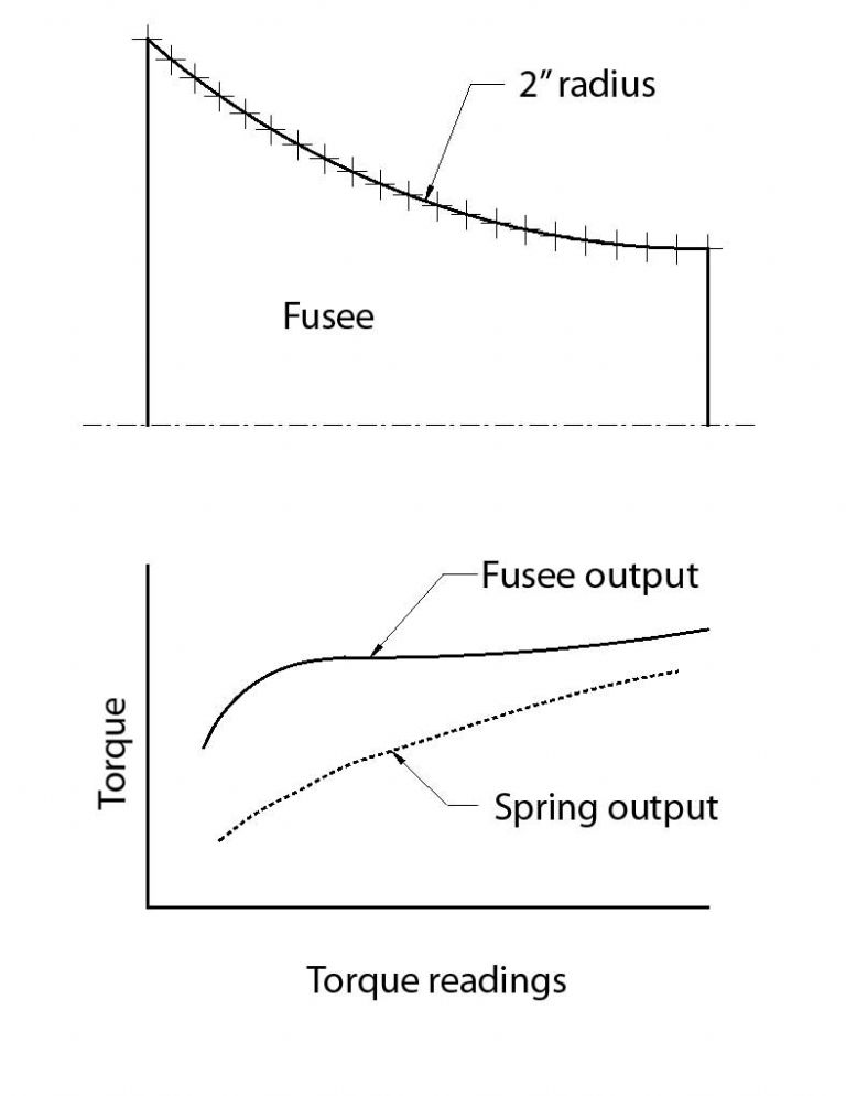
The main-spring output was determined by calculation using the (approximate) radii measured off the fusee. A sort of inverse determination.

In answer to your question –
“Is the profile you used a published one or is it made up or derived in some way?”
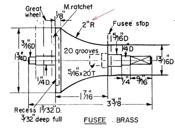
Yes. It was a 2” radius profile, taken directly from the drawing thus –

For various reasons John, I’m no longer in a position to alter the fusee profile.
In terms of setting up the fusee and main spring, I fear that their combination fails to provide useful `access’ to the so-called spring flat-spot.
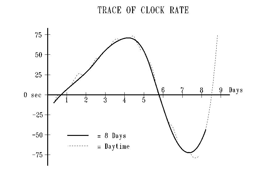
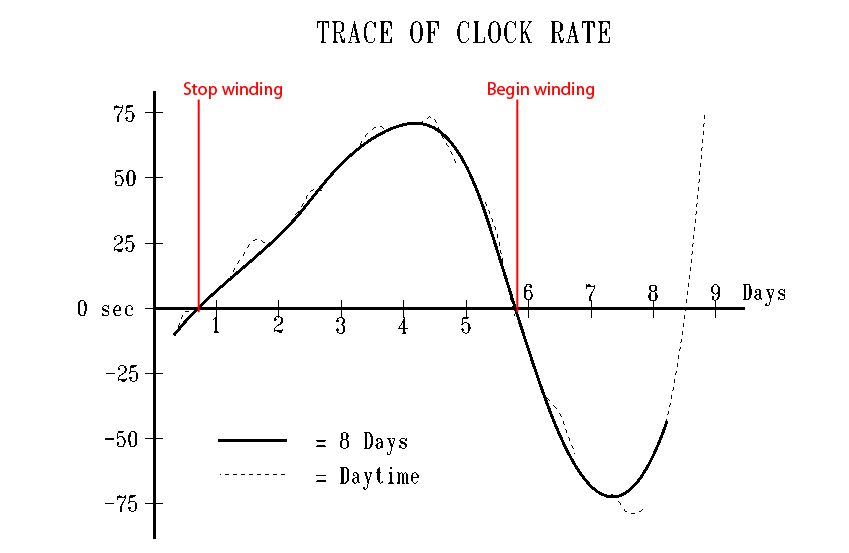
In other words, up to the point when the stop-work lever `kicks in’, the main spring is almost completely wound. Adding any more clicks to the barrel ratchet fully winds the spring, and the stop-work mechanism doesn’t engage. Removing barrel clicks and the clock stops before all of the fusee line has been used up. At the start of day 8, the arc (swing) of the balance wheel decreases, and the clock speeds up. See the dotted line between day 8 and day 9 on my graph.
John, I’m don’t understand your statements –
. . . the escapement is supposed to ration the unwinding of the mainspring with a time dependent element.
or
Now an increase in driving force by a well positioned finger on the driving train will cause a speed change. It shouldn't cause the train to free wheel. If your train is seriously sensitive it would appear to be effectively a freewheeling set up and not a time latched/unlatched process.
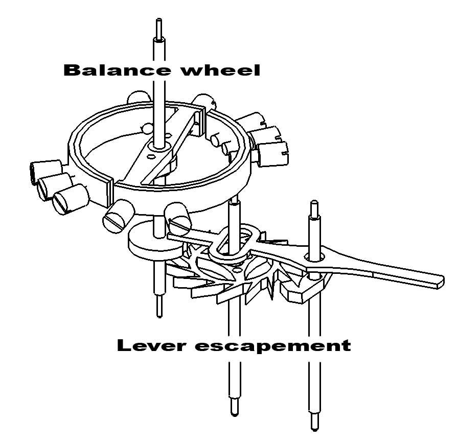
Applying extra driving force causes the balance wheel to spin through an increasing arc until the impulse pin travels around far enough to strike the outer edge of the escapement lever. I would need to understand what freewheeling means in this context.
Finally, from what I can see of the escapement wheel (under low power magnification), it appears to lock with no detectable twitching. As for adequate depth, I estimate about 0.01” (0.25 mm) for both entry and exit pallets. The geometry of the escapement as a whole, conforms well with the drawings, as far as I can tell.
I would welcome your further comments.
Regards,
Sam
Edited By Sam Stones on 27/10/2014 23:16:25
Gordon W.


