A Cornish conundrum

Advert

A Cornish conundrum

Home Forums Hints And Tips for model engineers A Cornish conundrum

Viewing 19 posts - 1 through 19 (of 19 total)
  • Author
    Posts
  • #531965
    Chris Gill
    Participant
      @chrisgill22114

      I wonder if anyone can suggest a way out of a dead end I seem to have created for myself.

      Some time ago, I decided to have a go at a freelance project and build a Cornish engine. As I don't (yet) have any experience with live steam I decided to use compressed air.

      Lots of time, planning and building later and I realised there was major flaw in my original idea. As the piston approaches the cut-off point it operates a linkage that closes the steam valve and residual energy in the steam continues to push the piston. But compressed air has no residual energy and so my engine reaches an equilibrium point where input pressure is balanced by leakage and restoring forces so it never actually closes the valve and just sits there hissing at me (OK, the valve isn't perfect!).

      It doesn't matter how much I tinker with the linkage or the input pressure, it never closes the valve.

      I've been puzzling over this for ages and the best I can come up with is to use an electromagnet to pull the valve closed at the right time. But I'm working at a very small scale so I'm still scratching my head over how to build the valves (equilibrium and steam) and find a position for the microswitches.

      Is there a design for a valve that magically cuts off a couple of seconds after its been told to close?

      Advert
      #30767
      Chris Gill
      Participant
        @chrisgill22114

        Getting a valve to do opposite things at the same time

        #531968
        Emgee
        Participant
          @emgee

          Electrically it would be done by a delay off relay, for air or steam perhaps something similar is available.

          Emgee

          #531972
          Nigel Graham 2
          Participant
            @nigelgraham2

            When you say "Cornish", I take it a beam-engine and double-acting steam, not an atmospheric engine? Is it rotative (with a flywheel) or reciprocating only (as was used for mine pumps)?

            A steam engine can work expansively on air. Many small model engines spend all their lives driven only by air; and it is common to test miniature loco chassis yet to be given a boiler, on compressed-air.

            Reading between the lines suggests to me you've nearly identified the problem as leaks and what you call "restoring forces" (friction?); but beyond them, suggests a valve-timing problem. Cut-off too early? Exhaust opening late or insufficiently?

            What type of valve are they? Slide, poppet, plug-cock? Some are more difficult than others to make steam (or air) tight.

            I expect here are people here with more experience than I have of this type of engine, but as a start, if you can show us some photos and even better, a sectional General Arrangement drawing, that will greatly help solving the conundrum.

            #531975
            Chris Gill
            Participant
              @chrisgill22114

              Hi Nigel

              It's a Cornish beam engine with steam (air in my case) pushing the piston up against the weight of the cross-head. After shut-off the piston continues to rise and linkages driven off a secondary beam operate the valves. The restoring force is the cross-head and that pulls the beams down again. The original was a pumping engine

              The valves were originally Cornish double-beat valves but mine are a little simpler – just a sliding piston that closes the ports.

              #531982
              Jeff Dayman
              Participant
                @jeffdayman43397

                Why not make a simple boiler to a proven design, and use steam? Could just be a pot type low pressure boiler, maybe one of Tony Wright's designs? Or make a boiler from a kit of parts from a ME advertisers?

                The old boys who built these original beam engines used steam, after all. Using electrical apparatus to get a steam mechanism going seems rather odd to me, but that's just my opinion.

                If running on air, you might be able to change valve event timing to admit air for a longer part of the stroke to get the engine to run.

                #531990
                Chris Gill
                Participant
                  @chrisgill22114

                  I agree – electrical valves just seem wrong but no matter how much I alter the timing, the valve never quite closes. The air pushing the piston is also operating the valve via the linkages. Other engines that I've built were reciprocating and had a flywheel to keep things moving past cut-off. The beast I'm trying to build has a pause at the top of the stroke, which allowed the pump buckets to sort themselves out, and a pause at the bottom of the stroke.

                  If I just push the valve stem down a little, I can get things to work until the next cycle. And there are two valves, essentially to let air in and out again, but they both have the same problem so to get it working I need both hands in the guts of it.

                  Hmm, lots of head scratching going on frown

                  #532054
                  Zan
                  Participant
                    @zan

                    A photo would help

                    #532057
                    Hopper
                    Participant
                      @hopper
                      Posted by Chris Gill on 05/03/2021 21:15:51:

                      Hi Nigel

                      It's a Cornish beam engine with steam (air in my case) pushing the piston up against the weight of the cross-head. After shut-off the piston continues to rise and linkages driven off a secondary beam operate the valves. The restoring force is the cross-head and that pulls the beams down again. The original was a pumping engine

                      The valves were originally Cornish double-beat valves but mine are a little simpler – just a sliding piston that closes the ports.

                      Sounds like you need to extend the period the "steam" valve is open for. But without a pic or sketch of what you have, no idea how you would achieve that. Might be a matter of modifying the linkage for greater duration? Or modifying the position of the port so they stay open longer?

                      #532062
                      SillyOldDuffer
                      Moderator
                        @sillyoldduffer

                        I thought the characteristic of a Cornish Engine was the use of a Cataract to control the valve, not linkages?

                        Cornish pumping engines worked most efficiently at a rate set by the operator, perhaps running continuously, more likely much slower, maybe a stroke every few minutes. This meant the engine could deal efficiently with varying amounts of water in the mine, only lifting water when it had too. Efficiency necessary because there is no coal in Cornwall.

                        A Cataract is a box that fills slowly with water until it tilts operating the valve, empties and resets. How often the engine strokes depends on how open the water tap is, which can be changed by the operator. Unlike other steam engines, the valve isn't worked by the engine through a linkage: the cataract is independent of the engine.

                        Not sure it would be possible to miniaturise a working cataract valve, in which case an electrical equivalent seems respectable. Although electrons would charge a capacitor rather than water fill a box, the operating principle is the same.

                        Dave

                        #532064
                        Hopper
                        Participant
                          @hopper
                          Posted by SillyOldDuffer on 06/03/2021 11:08:08:

                          I thought the characteristic of a Cornish Engine was the use of a Cataract to control the valve, not linkages?

                          Cornish pumping engines worked most efficiently at a rate set by the operator, perhaps running continuously, more likely much slower, maybe a stroke every few minutes. This meant the engine could deal efficiently with varying amounts of water in the mine, only lifting water when it had too. Efficiency necessary because there is no coal in Cornwall.

                          A Cataract is a box that fills slowly with water until it tilts operating the valve, empties and resets. How often the engine strokes depends on how open the water tap is, which can be changed by the operator. Unlike other steam engines, the valve isn't worked by the engine through a linkage: the cataract is independent of the engine.

                          Dave

                          I had a bore (well) pump that operated the same way on my last country property. Operated on compressed air from a compressor in the shed run down a flexible hose to the "pump" in the bottom of the bore hole. This was just a 4" stainless tube closed at both ends with a float inside and a couple of valves. Water, in scarce supply in the dry season, slowly filled the chamber, float floated up and eventually tripped the air valve and the compressed air shot the water up the pipe to the tank on the surface and the float then dropped down and the air valve closed. Still available new today. Has the advantage of only pumping when water is available instead of sucking an almost dry hole completely dry with a rotary pump. Never knew the principle was that old though.

                          #532215
                          Howard Lewis
                          Participant
                            @howardlewis46836

                            Being a n engine operating on the Cornish cycle, is the leaky valve the Inlet or the Equilibrium valve?

                            Maybe, ensuring that all the valves seal will solve the problem, since it sounds as if the engine is being set into equlibrium by the pressure leakage.

                            Also, the tappets need to be set correctly. Cornish engines were always started manually by the engine man (Putting his best hand forth" as J H Trounson quoted in "Cornish Engines and The Men Who Handled Them" Published by The Trevithick Society )

                            "The Cornish Beam Engine " by D B Barton (Cornwall Book )gives details of various engines, and many illustratuions, including pictures of the valve gear on Taylor's 90" at East Pool, but neither book seems to have a sectioned view )showing the valve gear.

                            Compressed air still has energy, and will expand if admitted to a cylinder and locked in, falling in temperature during the process..

                            HTH

                            Howard

                            #532305
                            Chris Gill
                            Participant
                              @chrisgill22114

                              Thanks to all who tried to help in spite of my rather vague question. Maybe a bit more background would have been a good idea to start with. I intended to post this last night but tried to show off by spending hours making a fancy meal and then fell fast asleep. Maybe some things should be left to the experts.

                              I'm trying to build a small scale (1/30) model of the biggest steam engine there is and using compressed air rather than steam. I went for the Cruquius engine because of the fascinating control gear and the excellent web site (**LINK**). I chose a small scale because I didn't think I'd get it through the door otherwise. I haven't built the cataracts or the hydraulic stays yet and, as someone said, miniaturising the cataracts will be interesting. The rest of it is working apart from the problem with the inlet and equilibrium valves.

                              With air, I don't need the condenser or the exhaust valve and I consolidated the annular piston and the main piston. The original was 12 feet across.

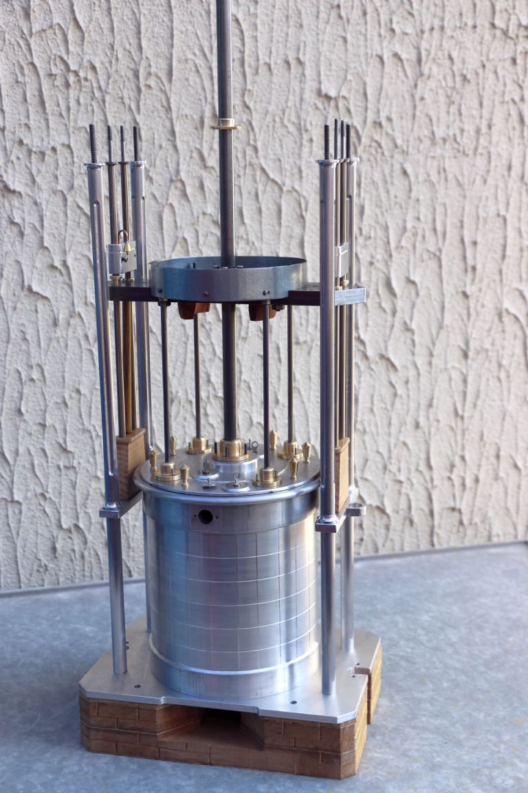
                              This is the cylinder before I put it in the engine:

                              img_1328.jpg

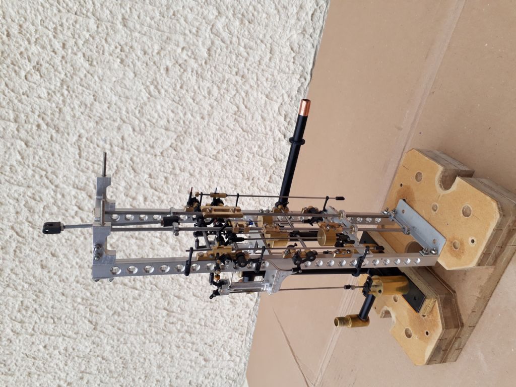
                              And one of the control gear (sorry its on its side):

                              2020-10-16 16.04.36.jpg

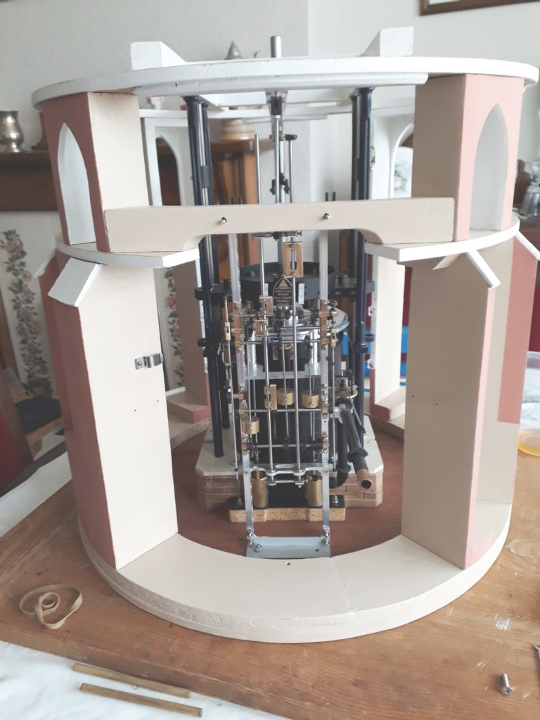
                              And the model so far with the cut-away building – an attempt to show off the 7-foot thick walls:

                              2021-03-07 10.22.59.jpg

                              In this engine, the piston moves the valve control beam, which moves the plug frame. The plugs move the horns, which move the angular transformers and close the valves. The cataracts release the scoggans and that lets the counterweights open the valves. So my problem is to persuade the engine to keep moving enough to close the valve while it needs air to keep it moving.

                              Incidentally, the last sub-page on the Cruquius site is the detailed restoration report and is a really interesting read. I've learnt a lot from project already – I even discovered that "junk" is a perfectly good engineering term.

                              #532313
                              Howard Lewis
                              Participant
                                @howardlewis46836

                                If you are modelling the Cruquius engine, you have a lot of beams to make!

                                A splendid site with good animations and explanations.

                                The cylinder was probably the largest Cornish engine cylinder made, since most were no larger than 90"

                                "Junk" is an accepted engineering term Sleeve valve internal combustion engines have a "junk head ring" at the top of each cylinder!

                                It doesn't just apply to what I make.

                                Please keep us posted as to your progress!

                                Howard

                                #532315
                                Former Member
                                Participant
                                  @formermember12892

                                  [This posting has been removed]

                                  #532435
                                  Nigel Graham 2
                                  Participant
                                    @nigelgraham2

                                    I knew these engines were governed by "cataracts" but didn't know their principle until Silly Old Duffer explained it above.

                                    Dave goes on to wonder if a miniature cataract can be made. I'd have thought it possible to time it, since that's a matter of throttling its water-feed, but the bigger problem may be whether the full device has sufficient mass to operate the valves. It might need a fair bit of experimenting.

                                    +++

                                    As an aside … some may know of Ron Jarvis' Silver- and Gold- winning, beautiful, fully-detailed miniatures of unusual or unique engines of historical significance. Among them was a Newcomen Atmospheric Engine, standing a good 18 inches tall, faithful to 18C practice, yea even unto the lead pipes he made for it, and fully working as original on its heady boiler pressure of 2lbs/in^2.

                                    To run its nearly-spherical boiler no bigger than a tennis-ball, too small for coal-firing, and anyway so it could be demonstrated indoors, he fitted it with a discreet electrical element with a control-chip hidden in the plinth. He used to joke about it being the only 18C engine built with computer control!

                                    Ron passed away several years ago now. I wonder what happened to his engines. I do hope they are not merely locked out of sight in some museum store, safe but unseen, by management-decision.

                                    #532987
                                    Howard Lewis
                                    Participant
                                      @howardlewis46836

                                      When I said largest, "Cornish" engine, I was being parochial and thinking in terms of engines in Devon and Cornwall. so omitted the Grand Junction. The Cruquius at 144" was the largest, but unusual in that it drove several beams and pumps.

                                      Probably the influence of Trevithick caused Cornish engines to be run on what he called "strong steam" (40 psi ) instead of the low pressures favoured by Watt.

                                      Maybe the Cornish cycle. using the equilibrium valve, may have improved economy a little, and circumvented the stranglehold that Watt tried to impose with his patents?

                                      Howard

                                      #533072
                                      Chris Gill
                                      Participant
                                        @chrisgill22114

                                        Howard – yes, I've been reading up on the arguments between Watt and others. Interesting.

                                        Actually, Cruquius was one of three engines, all with 12-foot cylinders and annular pistons. The first one had 11 external pumps with the same total lift as the 8-beam versions. There are also two internal pump beams, another pump driven off one of the main beams and an additional beam to drive the control mechanism.

                                        Nigel – I would love to have seen Ron's engines, they sound fascinating. You're right, the cataracts are going to be a challenge and then there is still the hydraulc stay (two rams that stop the piston creeping down from the top of its travel).

                                        Unfortunately, I've backed myself into a corner by ignoring rules of thermodynamics that I learned 40-odd years ago and never used since. Cold compressed air aint the same as hot pressurised steam so my valve will never close (the cataract controls the opening of the valve in this engine). And nothing in my build will handle hot steam (aluminium, steel, pipes soft-soldered …). With around 1000 parts so far, I don't want to start again.

                                        The temptation is to follow Ron's example and automate the steam and equilibrium valves. It feels like cheating but it keeps the rest of the engine looking and acting like the original. I can see another option – make two more cataracts with scoggans and all the rest, except I can't see where to fit them in. At 1/30 scale, my fingers are a yard across!

                                        #533081
                                        Howard Lewis
                                        Participant
                                          @howardlewis46836

                                          DO keep, us posted, please!

                                          Howard

                                        Viewing 19 posts - 1 through 19 (of 19 total)
                                        • Please log in to reply to this topic. Registering is free and easy using the links on the menu at the top of this page.

                                        Advert

                                        Latest Replies

                                        Viewing 25 topics - 1 through 25 (of 25 total)
                                        Viewing 25 topics - 1 through 25 (of 25 total)

                                        View full reply list.

                                        Advert

                                        Newsletter Sign-up