Now for a brief discussion on the various methods of producing bevel gears.
First, thanks to Nick for the drawings, very good! I’m sure the method would work, as would the use of a hacksaw and file. But my word it would be a bit tedious. I wonder what sort of templates would be needed to ensure accuracy, and how would you make them?
As an aside Richard mentioned the Hiraoka books; I’ve heard good reports about them. I have a friend who has an obsession with Shay locomotives; I’ll have to ask hin if he has the books.
Now onto the suggestion by ady of using a shaper. I considered this too, essentially I guess one is making a crude Gleason bevel gear planer. It seems a lot of work though, and secondly my shaper is sadly out of action at the moment, awaiting repair of a broken casting.
So finally we come to the production of the bevel gears on a milling machine. First, a statement; it is not possible to machine a true bevel gear on a conventional milling machine, with one caveat.
JohnS has succinctly described the two approximation methods, so I won’t repeat them here, but just make some comments.
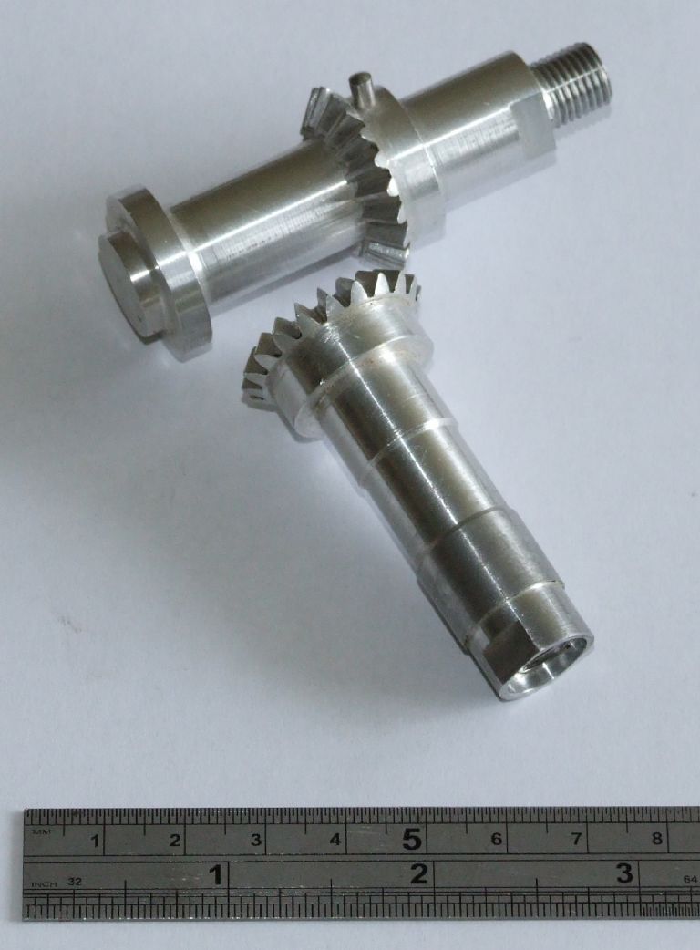
On the first method (that requires ‘adjustment’ afterwards) as I understand it the gear is designed using the DP at the outer diameter of the gear. An involute cutter is then selected that has the correct tooth form for this DP and the appropriate number of teeth. But, here’s the difficulty, this cutter has to pass through the tooth gap at the small end of the gear. So you cannot use a standard involute cutter. Instead you need a special involute cutter that has the correct form but is thinner than standard. Can anyone confirm this? As far as I’m aware these cutters are no longer available; at least I couldn’t find any, not even from China or India. I have made bevel gears in the past using this method, but I had the facilities of the main workshop at RAE Farnborough behind me. They lent me the special cutter required. Here are the gears prototyped in aluminium, the final gears were made in EN32 and were case hardened:
If you look closely at the lower gear you might be able to spot the ‘deliberate’ mistake.
The parallel depth method avoids the need for a special cutter as the design is based around the DP at the smaller end, and hence a standard involute cutter is fine.
Now onto the post by JohnS, really interesting. I downloaded the Gearotic demo last night and had a play. It looks very good, but I cannot output data from the demo so cannot see what the G-code looks like. Are the bevels generated true bevel gears, or do they use the parallel depth method? The other thing I couldn’t see how to control was the stepover of the tool, which determines the surface finish, trading this off against run time. The cutting time JohnS got is much quicker than mine. I wonder if this is due to a coarser stepover, or a more sophisticated toolpath. My CAM system will only interpolate X and Z, The Y axis never moves and A is only used as an indexer. It would be more efficient to interpolate 3 or even 4 axes. This would also allow one to generate a ‘Sturz’ style cutting strategy which would be more efficient and give a better finish for a coarser stepover. Further I don’t see why a tilting dividing head is needed? I didn’t use one, but just used the 4th axis as an indexer, no cuts took place while the rotary table was moving. It would have been possible to cut the pinion using a 3 axis mill, but this would have required a long series end mill. A 4mm ball end cutter with a flute length of at least 22mm would be a bit delicate! I will be cutting the crown bevel gears using 3 axes, as the teeth are much flatter, so we don’t need the 4th axis.
Now, back to the caveat. It would be possible to machine a true bevel gear on a manual mill by essentially replicating what the CNC mill does. In other words a long list of X, Y, Z and A co-ordinates that are stepped through by twiddling the handles. It wouldn’t half be tedious though.
Regards,
Andrew
Edited By Andrew Johnston on 05/06/2011 11:32:20
Sub Mandrel.


 They certainly lightened my day; excellent choice of accompanying beverages by the way!


