A Challenge – How Would You Machine This Part?

Advert

A Challenge – How Would You Machine This Part?

Home Forums Workshop Techniques A Challenge – How Would You Machine This Part?

Viewing 25 posts - 1 through 25 (of 84 total)
  • Author
    Posts
  • #69590
    Anonymous
      Here’s a tongue in cheek challenge!
       
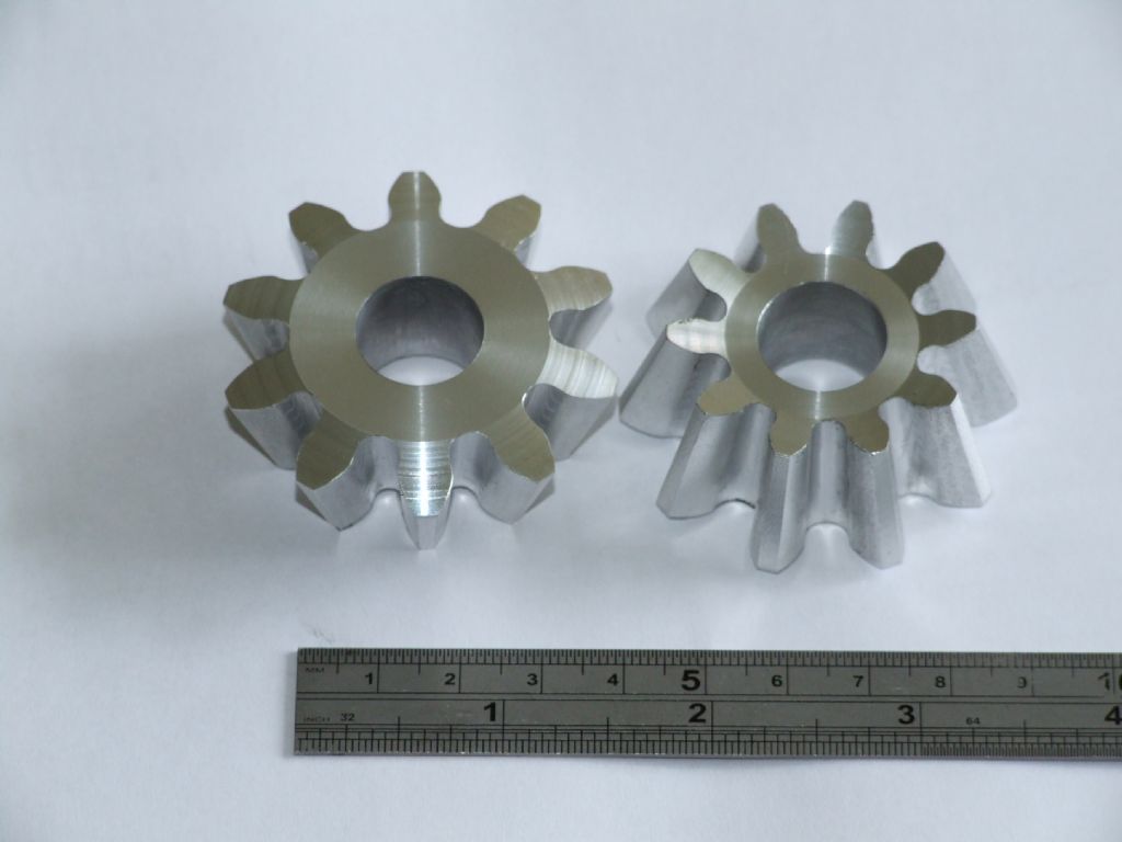
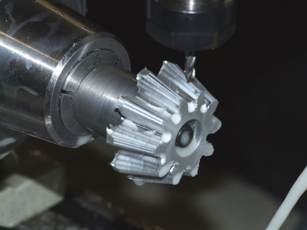
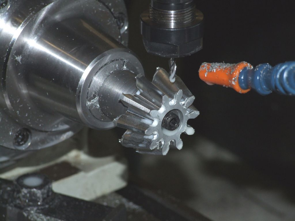
      How would you machine the part shown below? It’s a true bevel gear pinion, 10 teeth, 6DP, 3/4″ face width. The largest OD is just under 2″.
       
      As illustrated, the bevel gears are machined in aluminium; the final parts will be in cast iron. Note that. after deburring, the gears mesh together perfectly.
       
      So, what machines would you use, what accessories might be needed, and what tools would you use or need?
       
      Regards,
       
      Andrew
      Advert
      #15527
      Anonymous
        #69591
        WALLACE
        Participant
          @wallace

          Definetly one for CNC, no argument about it !!
           
           
          W.

          Edited By WALLACE on 02/06/2011 16:33:18

          #69592
          JasonB
          Moderator
            @jasonb
            If they are bevel gears for a traction engine diff then just cast them in iron and use as is, plenty about like that including mine.
             
            Jason
            #69593
            Donald Mitchell
            Participant
              @donaldmitchell68891
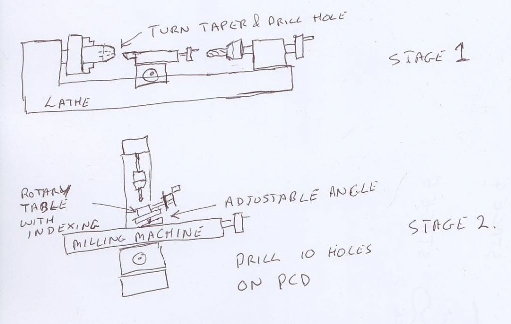
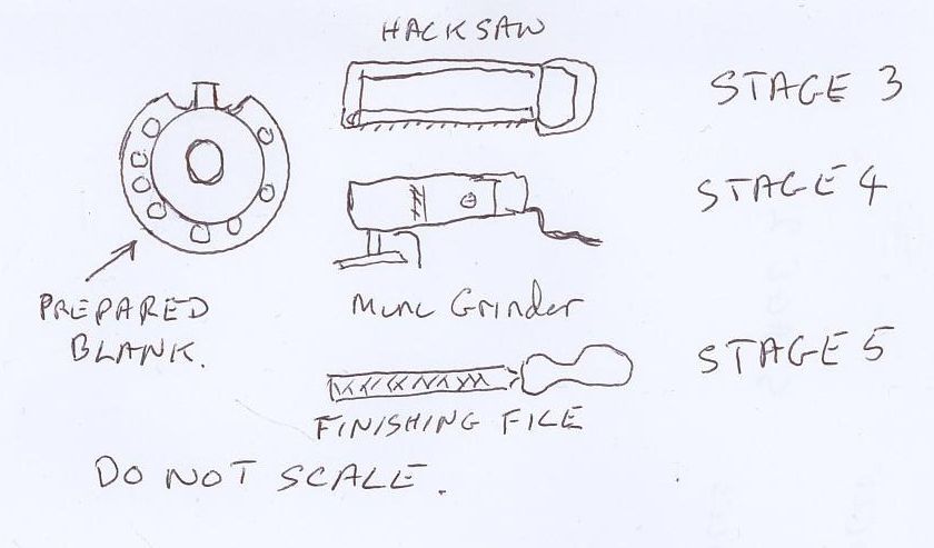
              I’d use my grandpa’s old hacksaw and finish the teeth off with a nice rat tailed file I bought in Woolworths about 30 years ago; I can work to about 2/10 of a thou with that file, who needs CNC
              Donald
              In Bonnie Scotland
              #69595
              WALLACE
              Participant
                @wallace
                 
                 
                Easey-peasey.
                I’d machine them in the same way as the aluminium version !!
                 
                W.


                Edited By WALLACE on 02/06/2011 17:27:37

                #69596
                Tony Jeffree
                Participant
                  @tonyjeffree56510
                  I’d send the drawings to John Stevenson attached to a suitable number of beer vouchers
                  Regards,
                  Tony

                  Edited By Tony Jeffree on 02/06/2011 17:12:58

                  #69597
                  Stephen Benson
                  Participant
                    @stephenbenson75261

                    Horizontal milling machine with a dividing head on an angle

                    Edited By Stephen Benson on 02/06/2011 17:16:31

                    #69598
                    dcosta
                    Participant
                      @dcosta

                      Hello Donald.

                      “I can work to about 2/10 of a thou with that file, who needs CNC” ?

                      I do. I have tendinitis in both shoulders so can’t be more than 1 or two minutes with a file swinging back and forth…

                      But I must say that by now I haven’t CNC at home.

                      I would like to have, but will not abandon manual control of the machines. I like it very much. Except when it contends with my shoulders or patience…

                      In fact I’m expecting the announced Tony Jeffree article about lathe screw control to start a new project.

                      Best regards
                      Dias Costa

                      #69599
                      mgj
                      Participant
                        @mgj
                        Depends on what it is for – but I have a couple of bevel pinions for the TE to do – a 4″ Little Samson in 6DP. I’ll do them in cast iron as a parallel depth bevel – see Ivan laws book. I will also do the bevel ring gear like that too. He does do a cast version which I used on the 3″ LS, but I fancy a change
                         
                        With a GHT VDH the blank  roll is easily achieved using the plate wheel.
                         
                        No CNC at all – fully manual devised during WW1. Aint exactly difficult with a dividing head and mill.

                        Edited By mgj on 02/06/2011 17:56:33

                        #69602
                        ady
                        Participant
                          @ady

                          I’d email the picture to Taiwan and ask them to knock some up.

                          #69603
                          ady
                          Participant
                            @ady
                            On a more serious note.
                             
                            Read up “gear wheels and gearcutting” by a.w. marshall
                            #69608
                            David Clark 13
                            Participant
                              @davidclark13
                              Hi Tony
                              And John would put it on a CNC mill I expect.
                              regards david
                               
                              #69614
                              John Stevenson 1
                              Participant
                                @johnstevenson1
                                A few options.
                                 
                                Probably the most accurate is to sent it to the local gear cutters to be cut on a Gleason Bevel gear cutter. that might be classed as cheating though.
                                 
                                Next is to mill it on a milling machine with universal dividing head that can tilt, like the BS0 and BS1 and take 3 cuts, one on centre, one above and one below centre. This does entail some hand filing of the addendum from half way down the face width to get to run correctly.
                                 
                                Followed by what MGJ says and cut to constant depth, again three cuts but no hand finishing. Only problem with this method is you have to do the pair, a constant depth bevel will not run with a normal bevel.
                                 
                                Then we get the CNC option, again needs tilting dividing head driven by stepper, now I have had to do a bit of guesswork here as Andrew hasn’t given any detail on the mating gear and this controls some of the parameters so I have taken a guess at a 10 tooth driving a 45 to get a pitch angle matching the photo.
                                 
                                Literally 10 minutes work filling boxes in gets me this.
                                 
                                 
                                This drawing now gives me all the information I need and 5 minutes later i have the code for this [ which i don’t need to look at, just load it and Mach3 tells me it will take 1 hour 58 minutes and 53 seconds to cut this.
                                 
                                 
                                And this on the little KX1 mill, run time just below the screen.
                                 
                                John S.

                                #69616
                                Tony Jeffree
                                Participant
                                  @tonyjeffree56510
                                  Posted by David Clark 1 on 02/06/2011 21:25:04:

                                  Hi Tony
                                  And John would put it on a CNC mill I expect.
                                  regards david
                                   
                                  Hi David –
                                   
                                  Is there another way?
                                   
                                  Regards,
                                  Tony
                                  #69617
                                  John Stevenson 1
                                  Participant
                                    @johnstevenson1
                                    Forgot to add in the previous post that the program is expecting a cutter of max diameter of 0.1786 so i programmed a 5/32 as being the nearest stock size but could have used a 4mm or a 4.5mm cutter so no expensive tooling needed.
                                     
                                    John S.
                                    #69619
                                    Steve Withnell
                                    Participant
                                      @stevewithnell34426

                                      I’d approximate and use parallel depth method to cut manually on my mill drill…but only because I haven’t bought a KX1 yet and the lust grows daily…

                                      #69620
                                      Nicholas Farr
                                      Participant
                                        @nicholasfarr14254
                                        Hi,

                                         
                                        I give up must be an easyer way.
                                         
                                        Regards Nick
                                        #69622
                                        ady
                                        Participant
                                          @ady
                                          So, what machines would you use, what accessories might be needed, and what tools would you use or need?
                                           
                                          A shaping machine and some hss tools, with the blank mounted on a dividing head which could be set over at one end for the bevelly tapery bit.
                                          Do the narrow cut.
                                          Set over left. Do the left hand cut
                                          Set over right. Do the right hand cut
                                          #69630
                                          Stewart Hart
                                          Participant
                                            @stewarthart90345
                                            All methods suggested are feasable as long as they end up fit for purpose, so the most important thing you have to consider,
                                             
                                            WHATS IT FOR
                                             
                                            Stew
                                            #69633
                                            Richard Parsons
                                            Participant
                                              @richardparsons61721

                                              In chapter 5 “Line Shaft”, 6 “Machining the gear cutters”, 7 “Machining the gear teeth” and Appendix A “You can machine Skew Bevel gears” of his book The Climax Logging Engine (ISBN 0-914104-09-8) the author Kozo Hiraoka details everything you need to make bevel gears in your lathe. He details the jigs, gauges, the cutters and the formula etc. He also tells you how to make the stuff and then to cut the wheels,

                                              Hope it helps.

                                              Ok he is working with ‘skew gears’ but you just omit the ‘off set’. You may have trouble getting the correct ‘wire size’ for your 6 DP 10 tooth cutter. I do not know where to find them. ‘Hiraoka samma’ tells you how to calculate it.

                                              I have used gauge plate to machine cast iron valve seats. Take it slow and gentle and you can do it.

                                              Edited By Richard Parsons on 03/06/2011 11:03:47

                                              Edited By Richard Parsons on 03/06/2011 11:08:52

                                              #69652
                                              John Stevenson 1
                                              Participant
                                                @johnstevenson1
                                                Come on then Andrew, don’t keep us in suspenders ?
                                                 
                                                John S.
                                                #69660
                                                Anonymous
                                                  Oeeeer, we can’t have that; fortunately my imagination isn’t that vivid!
                                                   
                                                  The short answer is that the gears were machining on a 4-axis CNC mill. It is not possible to machine them on a manual mill, with one extremely tedious exception.
                                                   
                                                  I have a number of comments and queries, which I’ll post later today after I’ve been flying, or decided that the weather isn’t playing ball.
                                                   
                                                  Regards,
                                                   
                                                  Andrew
                                                  #69666
                                                  Anonymous
                                                    So, the weather is not good, we’ve got alto-stratus and some alto-cu here, otherwise known as crap off the North Sea, so flying has been postponed.
                                                     
                                                    Thanks to everyone for the replies. Rather than one long post I’ll do several shorter posts. First a few general notes.
                                                     
                                                    The mating crown wheel will be 36 teeth, so John S wasn’t far out. These are true bevel gears, so they cannot be cut on a horizontal mill with a dividing head. I’ll discuss this in another post, as there are some things I would like to clarify on the cutting of bevel gears on a manual mill.
                                                     
                                                    Congratulations to WALLACE for getting the answer correct in the first reply, CNC all the way.
                                                     
                                                    JasonB is also correct, these are for the differential on a 4″ scale SCC Burrell. I admit that casting was the one solution I hadn’t thought of. I know that full size engines often used ‘as cast’ gears in the differential, presumably mainly for cost reasons. Since the full size engines often used only 6 or 8 teeth on the bevel pinions they would have also been heavily undercut and hence difficult to produce by machining. It would have been an interesting exercise to make the patterns and have the gears cast, but of course you still have the problem of how to make the pattern, chicken and egg? I’d use the CNC mill to make the pattern; it’s a couple of keystrokes in the CAD program to alter the scaling of the solid model to allow for shrinkage, about 1/8″ per foot or 1% for cast iron.
                                                     
                                                    Donald, yes you could use a rat tailed file. But the radius at the bottom of the small end is just over 2mm, so may I suggest that a mouse tail file would be more appropriate. You’d probably have to ask for a wee, sleekit, cow’rin, tim’rous beastie file though.
                                                     
                                                    On books, I do have Ivan Laws book, it’s good as far as it goes, but, it seems rather weak on the theory. I haven’t heard of the Marshall book, I’ll have to have a look. I normally use ‘Gear Design Simplified’ from Industrial Press, Machinery’s Handbook and the internet for design information.
                                                     
                                                    Regards,
                                                     
                                                    Andrew
                                                     

                                                    Edited By Andrew Johnston on 04/06/2011 11:19:44

                                                    #69670
                                                    Anonymous
                                                      Now to discuss how, and why, I did this machining the way I did. The whole farrago started because I didn’t agree with some of the numbers given on the drawings for the bevel gears in the differential for the traction engines I am building. I’m not interesting in spending hours making parts only to find they don’t fit because the drawings are wrong. I like to make sure I understand the numbers and how the part fits with its related parts before machining.
                                                       
                                                      Having spent some time working through the design of bevel gears I concluded that the drawings are slightly wrong; 3 thou out, not much, but 3 thou is 3 thou! It is not possible to machine a true bevel gear on a horizontal mill; it needs some adjusting afterwards and needs a special cutter. So naturally I turned to the parallel depth method. I did in fact redesign the whole differential using parallel depth bevel gears. I did, of course, consider buying ready made gears from my supplier, but I wasn’t terribly happy about the quality, the gears were expensive, and being awkward I wanted to machine them myself. Eventually the little light bulb illuminated (dull of course as it’s an energy saving bulb) and it occurred to me I could CNC mill the gears.
                                                       
                                                      Obviously to do this I needed a solid model. Easy enough to do in principle; I knocked up a basic gear in about 30 minutes. But as always the devil is in the detail. We all know that the tooth form is an involute curve, but how do you draw an involute curve in the CAD system. What part of the involute curve do you use, which of the infinite number of involute curves is correct, what about undercut clearances and root radii? It took me many hours of book buying, reading, drawing and internet searching to sort all this out. Plus the inevitable wobblies with the CAD software. In contrast the CAM program and G-code generation was fairly quick, apart from an annoying bug in the CAM software. For some specific operations the G-code generated didn’t agree with the toolpath shown.
                                                       
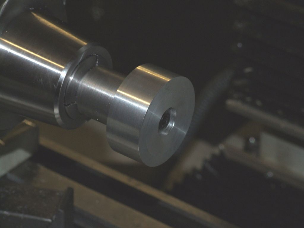
                                                      Here’s the sequence of machining, first the blank, it’s just a cylinder, diameter and length are easy to get from the CAD/CAM system.
                                                       

                                                      Next, after the roughing cuts:
                                                       

                                                      And after the final cut:
                                                       
                                                      All cutting was done with a 4mm three flute carbide ball nose cutter running at 5000rpm and 400mm/min, giving a conservative chip load of 0.027mm per flute. Total cutting time was about 2 hours 45 minutes. The chamfers on the back and front were done on a normal lathe, using the same arbor mounted in a collet chuck.
                                                       
                                                      How long have I spent doing this? Too long! I didn’t keep a note of times, but the following are rough estimates:
                                                       
                                                      Design calculation on the proper bevel gears: 8 hours
                                                      Designing the differential using parallel tooth bevels: 4 hours
                                                      Designing a 3D model of the bevel gear with correct tooth forms: 40+ hours
                                                      CAM software and G-code generation: 8 hours
                                                      Machining a backplate and fitting a 5C collet chuck to the mill: 6 hours
                                                      Loading, setting and cutting time for two pinions: 6 hours
                                                      It’s interesting to note that by far and away the biggest task was the design phase. Of course I now know a lot more about bevel gears (!) so if I do it again I’ll be a lot quicker. As an aside the cutting time for the bevel gears wasn’t wasted. During the time to machine the two gears, over two nights, I cleaned up the workshop, made and ate supper twice, and did most of the turning trials that have been reported elsewhere on this forum.
                                                       
                                                      Regards,
                                                       
                                                      Andrew

                                                    Viewing 25 posts - 1 through 25 (of 84 total)
                                                    • Please log in to reply to this topic. Registering is free and easy using the links on the menu at the top of this page.

                                                    Advert

                                                    Latest Replies

                                                    Home Forums Workshop Techniques Topics

                                                    Viewing 25 topics - 1 through 25 (of 25 total)
                                                    Viewing 25 topics - 1 through 25 (of 25 total)

                                                    View full reply list.

                                                    Advert

                                                    Newsletter Sign-up