As was suggested some weeks ago, I’ve added a couple of photographs to my CLOCK album. The first shows the bi-metallic balance wheel in its cage and the second was taken a little closer.
For an impression of size, the graduations are millimetres, the balance-wheel arbor is 1/16″ dia., while the ten timing screws are threaded 10BA. The heads of some of these screws may have to be hollowed out from the threaded end, should they be found to be too heavy during the regulating process. This hollowing out leaves a shell to create the impression that all the screws are of equal weight.
At this close range it is clear that having stood for more than 25 years, more cleaning and polishing is necessary. To the right of the wheel can be seen tiny dots which are blow holes in the brass. I tried five times before I succeeded in minimising the size of these holes, and can’t imagine repeating the process without a proper workshop.
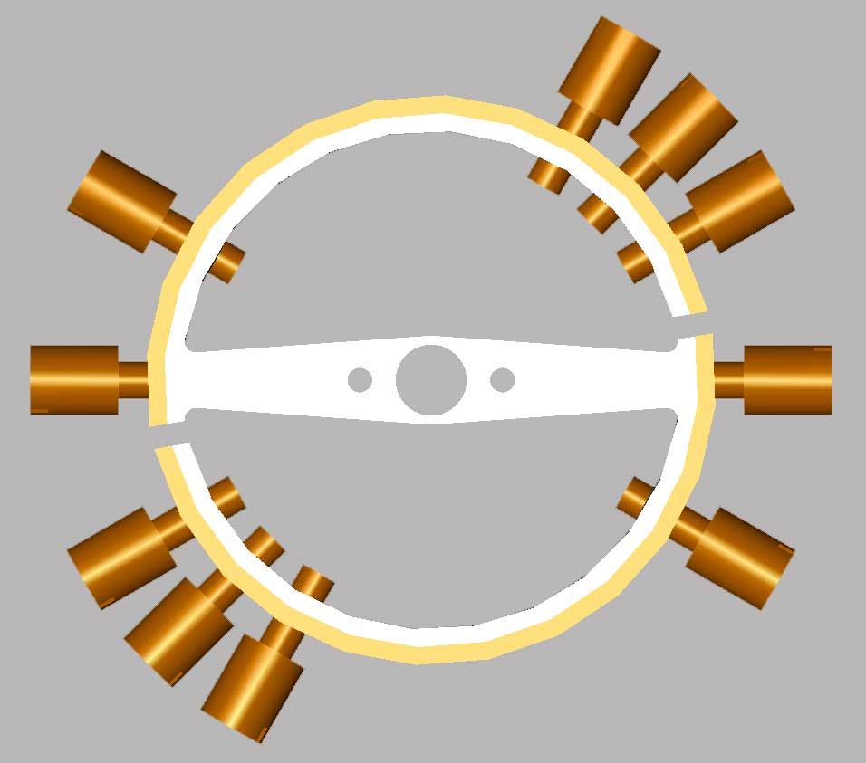
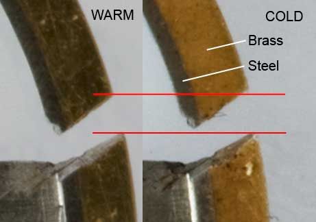
Although not particularly clear, the wheel is split in two places so that the bi-metallic action can take place.
I haven’t reached the point of making the spring as yet, but my first attempts will use a 0.008″ steel guitar string, this happens to be the size I determined using Moment of Inertia calculations. I’m presuming at this stage that the spring properties will suffice rather than go to the expense of the preferred metal, Invar I believe.
The drilled holes through the spring stud and the spring collet at 0.8mm dia. are just visible ready to take the ends of the spring. The steel collet has been split for adjustment purposes.
Below the balance wheel is the roller and impulse pin which engage with the lever as part of the escapement. While they are virtually complete, the detail of this latter mechanism must wait until I’ve built one or two more parts.
The bearings for the balance wheel and the lever arbors are from 1/8″ dia. silver steel and have been heat treated to be pot-hard.
That’s about all I can tell you at this stage, but I welcome any questions.
Billy Mills.


