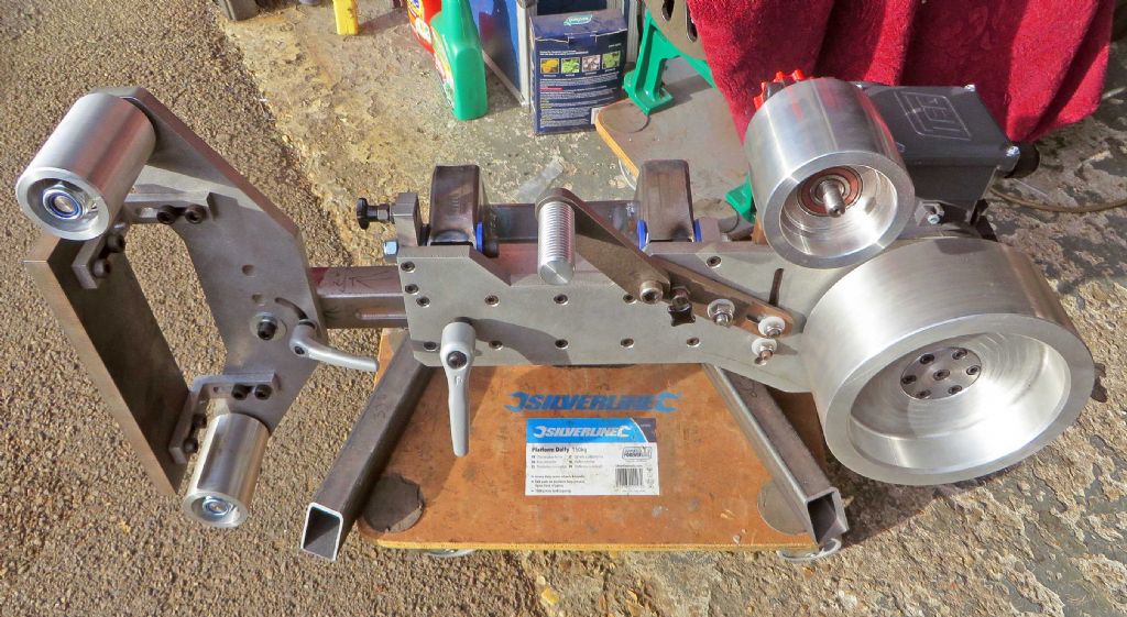
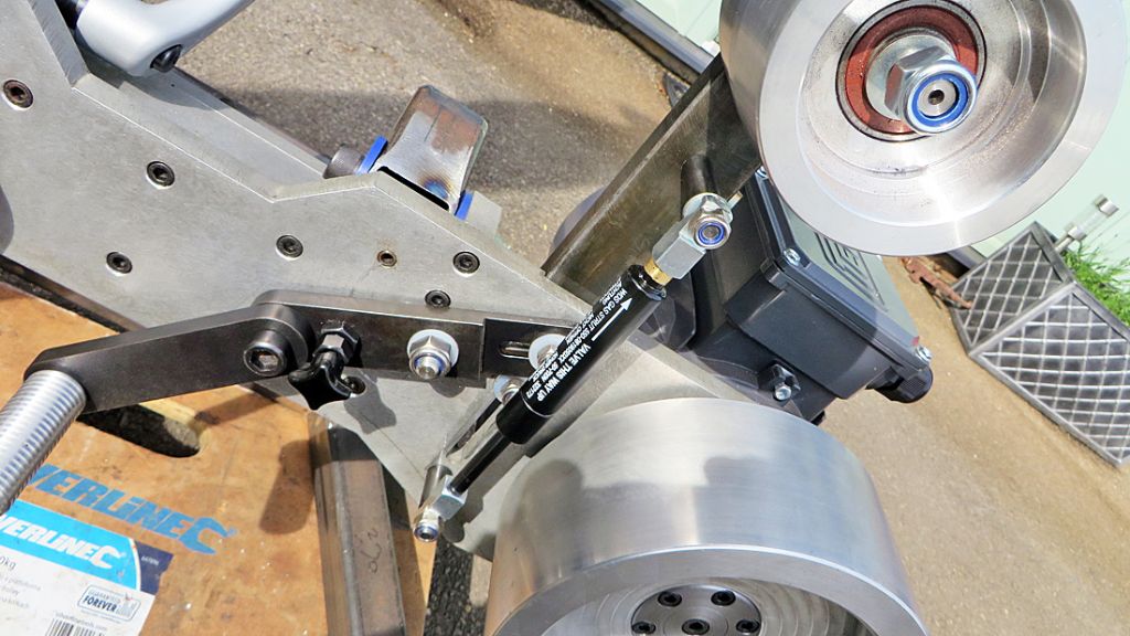
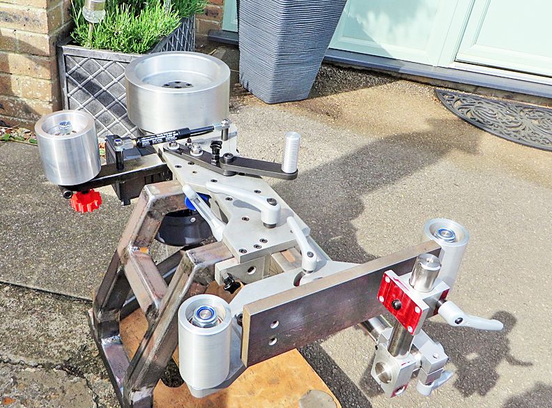
This project is still ticking along slowly. Finally got a new motor but have had to go with a 24mm shaft instead of 19mm so the hub will need altering, also the large drive pulley will need taking out a bit to allow room for the key way.
I am not able to machine this because of size so it will cost a bit to have done. Also I do not think that my S7, (and my skill!) are up to the accuracy need to avoid run out on such a large diameter pulley.
All now away being done for me.
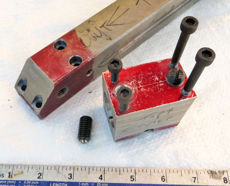
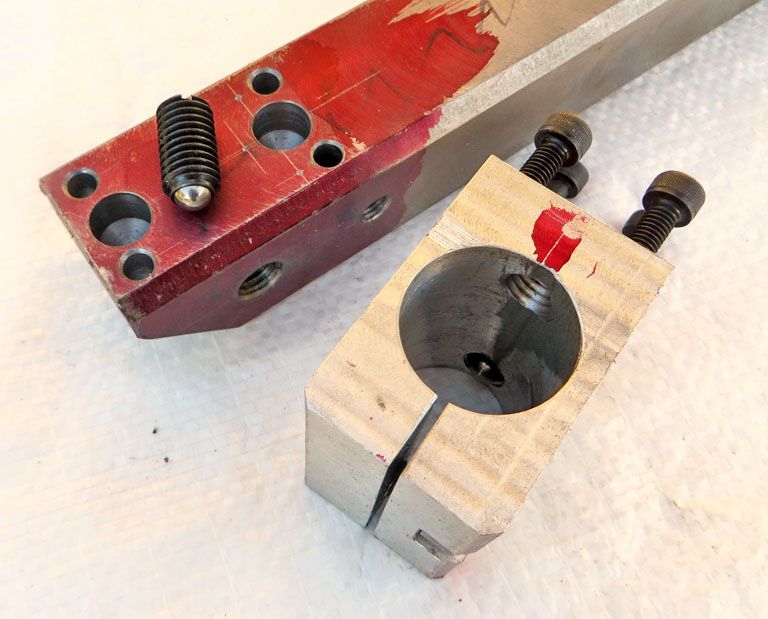
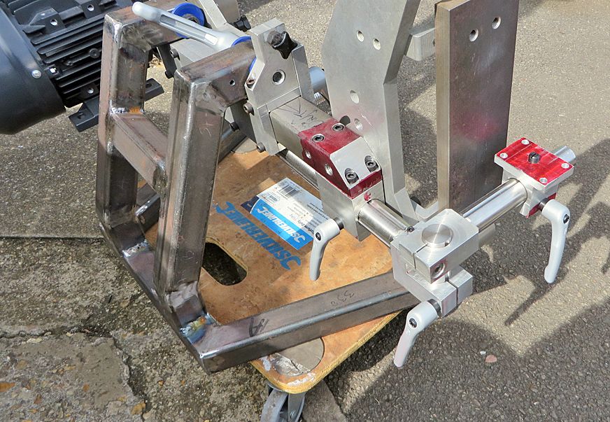
I have however made progress on the outboard end parts; machined the parts to take the main 30mm stainless rod that will carry the table:
This holds the two 12mm spring plungers that will engage in the 30mm table rod to enable indexing at vertical and horizontal table positions.
Next job it to mill the two circular grooves to take these plungers.
Hope that folks find this of interest, if not let me know and I will stop!
Your table only looks to be 200 mm long and not the 2000mm in the title?
Cheers Clive
I think you will find that the 2000mm refers to the length of the belt not the table. It has a lengthy path to enable use vertically horizontally and most points inbetween
Looking good Martin, it looks like it's a lot of work! This summer I built a 50x2000mm (or 2×72" belt grinder of Brian House kits. Much simpler than what you're building tho. What VFD and motor are you using?
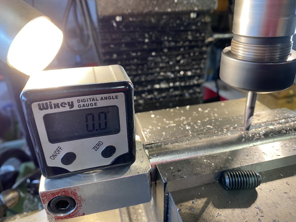
here is today’s bit, starting on the indexing of the table support bars that take the 6mm and 8mm spring ball plungers.
I spent a lot of time resetting the vice to be dead square and level for this operation as it is crucial to the table geometry.
Used a 6mm solid carbide ball nose cutter and played around with speeds and feeds, I get the impression that one must work the cutter hard in stainless (304)?
I have a need for a fairly powerful belt linisher and they are very expensive. There are loads of different build threads available on the 'Net and YouTube. I looked through and came across this one by Phil Vandelay in Germany. It seemed a well engineered project that allowed horizontal and vertical use, probably a bit over engineered truth be told.
Link to first video here:
I'm a bit late ,I watched this series yesterday on YT awesome build
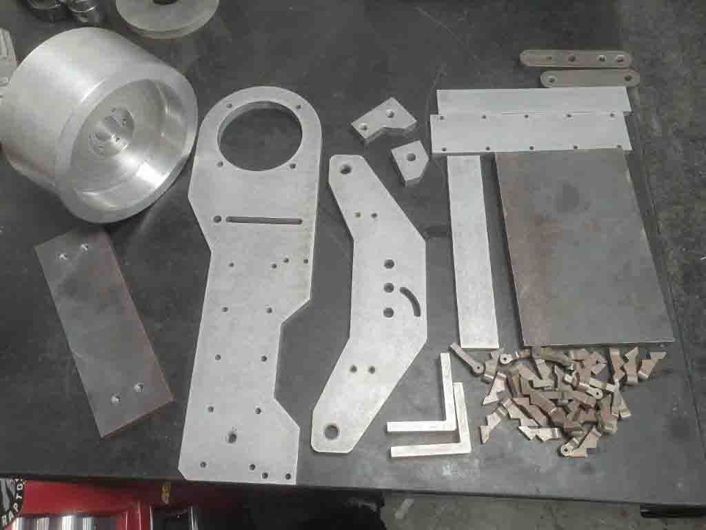
After looking at the series of three videos several times and realizing that there was no way that I could cut the very thick 15mm materials with what I have available i decided to get the larger parts water jet cut. The large drive pulley would also be too large for my Myford so I decided to get that machined also.
I coughed up the dosh for the plans and was delighted to see how comprehensive they were.
I pick up the water jetted parts on Monday morning so will start the project when a few more bits including the motor have been sourced.
Here are the parts awaiting pick up:
I will try and remember to take photos as I (slowly) progress, quite looking forward to this as it will stretch my skills to the limit!
This project has been on the back burner for a while as we have been very busy with other items.
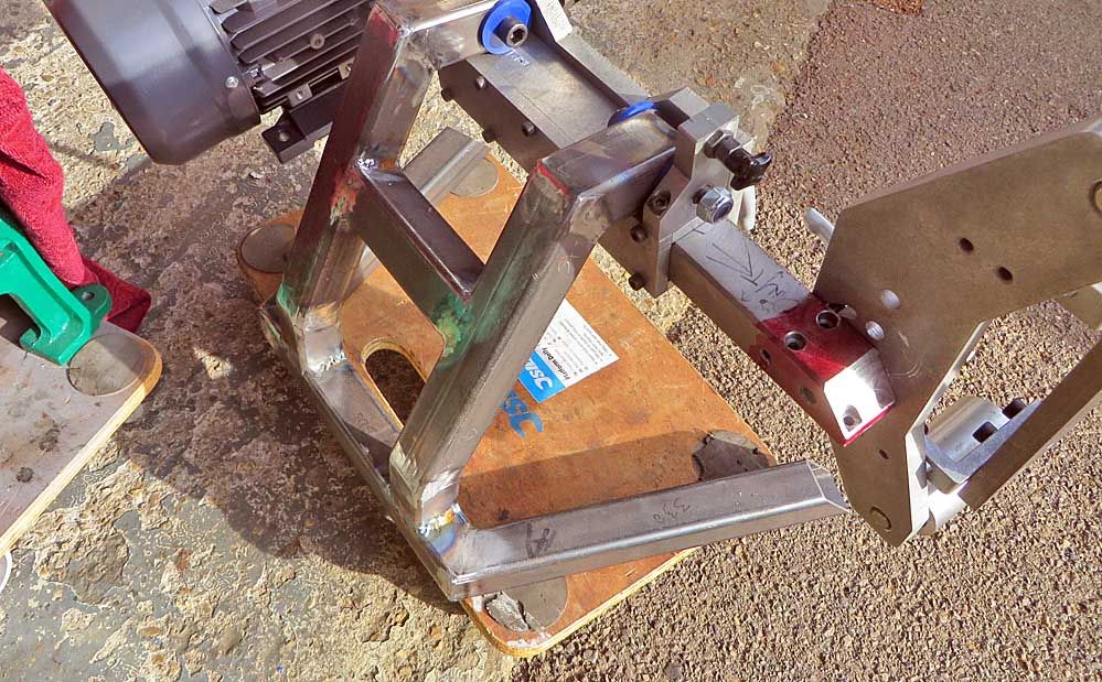
However I finally got around to having a go at TIG welding up the stand frame. This went well for the most part but I had to be careful to do all my tacking at opposite sides of each part to avoid distortion as much as possible.
Most of the welds came out OK but one or two burnt through the tubing and accessed non argon shielded air which caused some dirt etc to get in the weld.pool. Also I have not yet tried the foot pedal so sometimes the job gets too hot.
The other tricky part of the stand was getting the top and bottom sections dead level; this was achieved by only tacking the back section so that the upright could be levered into position with a digital level, then firmly clamped and the front then tacked. This worked out well.
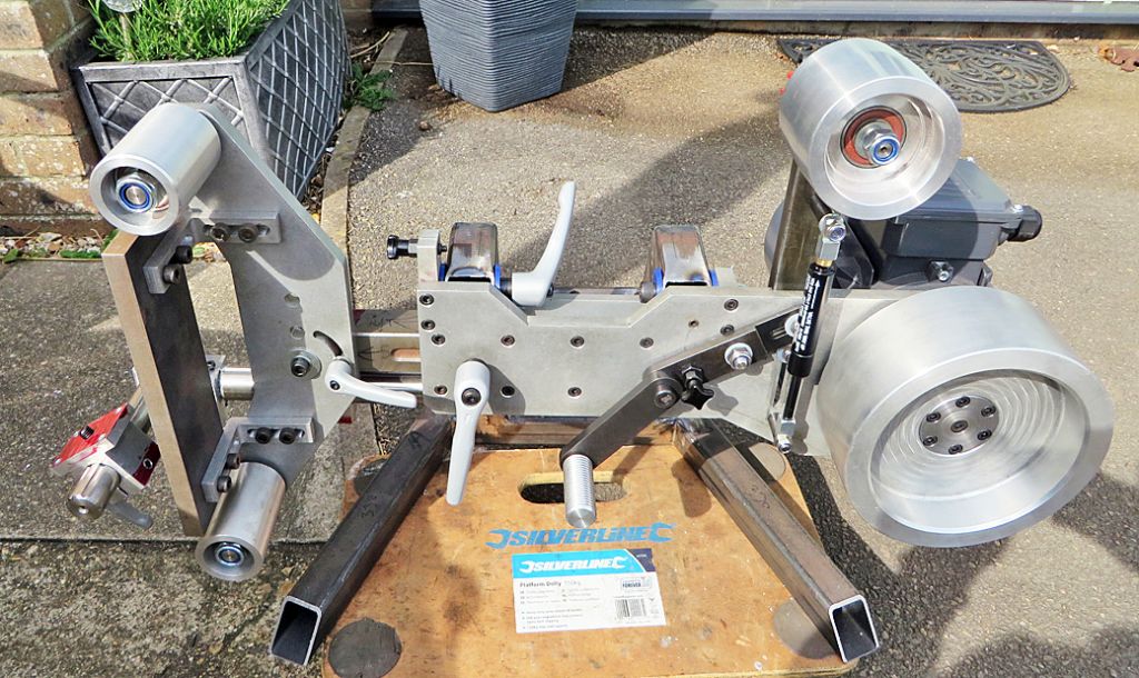
It was also useful to be able to use the main body frame as a means of setting the main fulcrums inline. The machine now operates both vertically and horizontally quite accurately to my surprise! Some balance issues to sort out as the front end gets the parts added when made. This is it so far:
I am going to cold blue all the steel items and will probably leave the alloy as is unless there is some kind of blacking product for aluminium? Anodising is way too expensive!
Of interest to me. Perhaps the "apparent lack of interest" results from members not bookmarking the thread and missing updates, which as you are busy progress tends to be a little spasmodic like most of my projects. Hopefully you will continue updating.
Of interest to me too. I hadn’t seen this build before maybe because I always tend to look at the ‘latest forum posts’ section on the home page. Keep up the excellent work it certainly looks well built.
I had not seen this thread before. Very interesting. And nice work. Looks like you found out the hard way that stainless steel is not the most fun stuff to machine as it work hardens along the way!
Having bought over 100 50mmX 2.1m belts at an auction, it had been the plan to make a machine. So reading of your work gives me ideas – thank you. Don't stop now ! Noel.
Hey Martin good progress, looking like a fine build! I have a 50×2000 belt grinder, as for belts I think it depends what you're going to use it on. For hard steel I use ceramic belts 40 grit for stock removal and then finer ceramic belts up to 100 grit for a finer finish. Then a Trizact 100 grit for finishing. Good brands such as VSM, 3M and Norton, but there are lots more which are fine as well.
I had a need to 'convert' an M6 thread to M10 x 1. Thread insert did the job, but I found it very difficult to get the insert correctly engaged. Six attempts to get two good ones. The kit came with ten, so not a disaster.