6″ Ruston Proctor Traction Engine – Model Build

Advert

6″ Ruston Proctor Traction Engine – Model Build

Home Forums Traction engines 6″ Ruston Proctor Traction Engine – Model Build

Viewing 13 posts - 51 through 63 (of 63 total)
  • Author
    Posts
  • #396673
    Paul Lousick
    Participant
      @paullousick59116

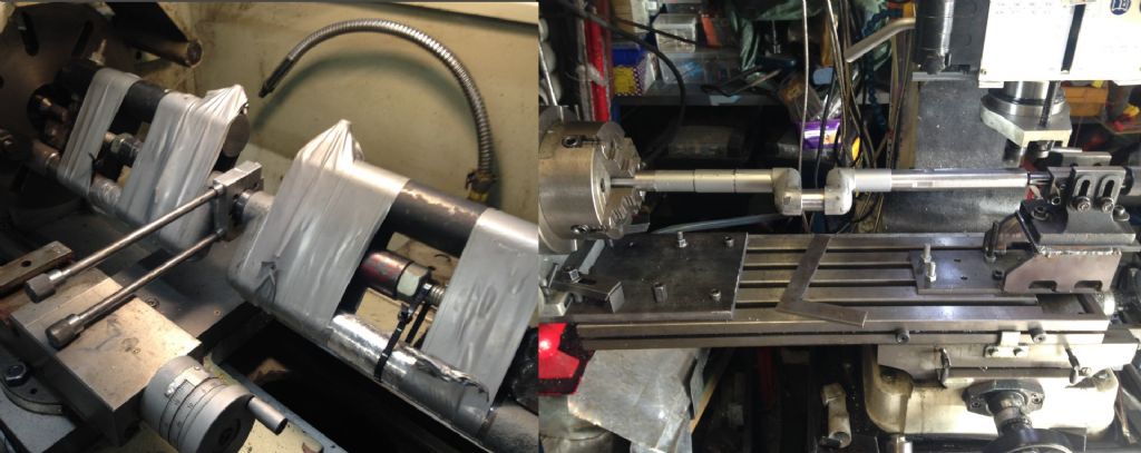
      The crankshaft jounal for the connecting rod was finished by lapping with a home made tool.

      The temporary wings cast on the end of the crankshaft for turning were removed and the shaft ends turned to size. Even though the shaft was located on lathe centres, there was a small amount of chatter as I was turning the ends of the shaft. The addition of a fixed steady eliminated the chatter.

      The shaft diameters for each pulley/eccentric were stepped for ease of assembly so the inner most one slid over the outer one and did not require pressing over it.

      Keyways then cut with one end clamped to jaw in a rotary table and the other supported in a lathe centre. (Again, special tooling had to be made to raise the fixed centre. Making tools took longer than the actual machining of parts).

      2105 crankshaft lapping.jpg

      Advert
      #396676
      David Davies 8
      Participant
        @daviddavies8

        Paul,

        thank you for copying these files across, your graphic account of the Ruston build is captivating reading.

        Cheers

        Dave.

        #396701
        Paul Lousick
        Participant
          @paullousick59116

          Thanks Dave,

          I have received lots of helpful information from members and just returning the favour.

          Paul

          #396793
          Paul Lousick
          Participant
            @paullousick59116

            Eccentric Sleeves

            I did not make the eccentrics and straps in the conventional way with groove in the straps on the inside. Instead I put the groove in the eccentric. (I was advised to do it this way by a machinist who has been making locos and traction engines for a number of years.) The mating surfaces are still the same diameter and width. Machining the strap this way is much easier than trying to plunge cut an internal groove to a specific diameter. Turning the eccentric boss is just as easy because all of the surfaces are on the outside. (I recently found a drawing in an early copy of ME with the eccentric sleeve only the width of the groove in the eccentric boss. Looks like they all work OK).

            eccentrics 2.jpg

            The castings were faced on both sides, rough bored and position of cut marked.

            Holes for clamping bolts drilled and casting cut in half. Mating faces then machined flat.

            Special bolts were made to assemble the 2 halves and the straps bolted together with a piece of shim material between them which can be replaced with thinner section as the eccentrics wear.

            2205.jpg

            #396794
            Paul Lousick
            Participant
              @paullousick59116

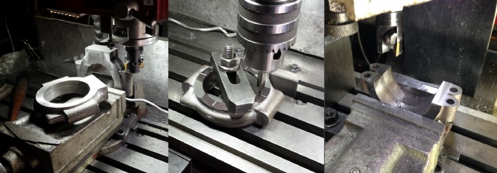
              The eccentric straps could not be held in a lathe chuck because of their shape so make a simple jig to machine the final bore. I use a dial indicator to locate and clamp it approximately on centre and then bored it to size. As the running surface is the smaller diameter, it could simply be bored thru and easily measured to achieve the exact size.

              The outer groove was then cut on the outside edge. Then the strap turned over in the jig to machine the groove on the opposite side using the DTI to centre the strap in the jig. This diameter only requires clearance with its mating part, and a small inaccuracy with running axis is not critical. 2208.jpg

              Eccentric Boss

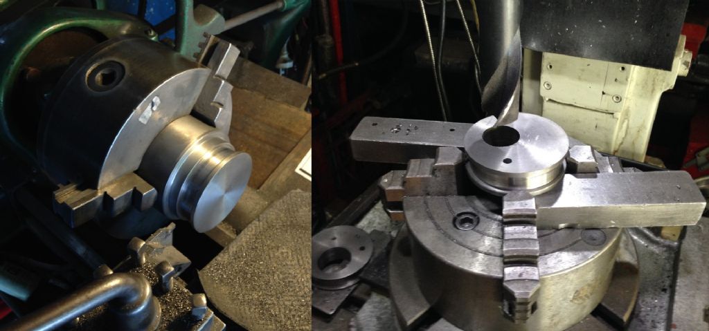
              The design for the 2 eccentrics on the supplied drawing had them both as part of the same part but I made mine as two separate units with a dowel pin setting the angle between them.

              The outer shape of the eccentric was turned on the late. (checking for a running fit with the sleeves). Locating the position of the offset hole for the shaft and dowel hole is difficult on the lathe, so I transferred it to the mill and used a rotary table and the digital readout on the table.

              2201.jpg

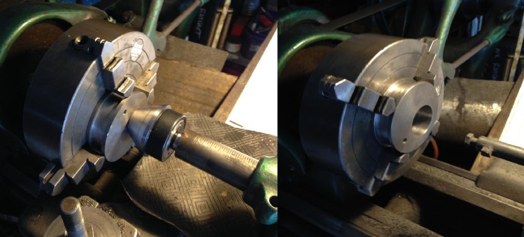
              Then moved back to the lathe and held the eccentric on centre while tightening the 4 chuck jaws. The hole for the crankshaft then bored to finish size.

              2203.jpg

              #396918
              Paul Lousick
              Participant
                @paullousick59116

                Connection Rod

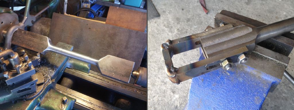
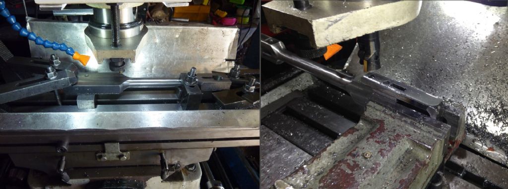
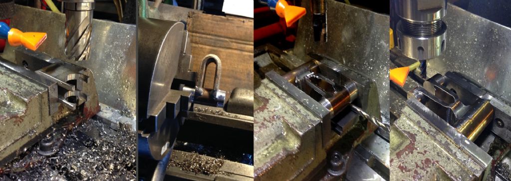
                The connection rod was turned from a rectangular piece of 4140 grade steel.  The material is harder to machine but has a higher tensile strength.  Then the holes for bolts and a slot for a tapered clamp wedge machined for the big end bush.

                I had trouble trying to bend the saddle for holding the bush so fabricated a welded version instead out of flat bar.  The 4 sides, holes for bolts and slot for the wedge machined prior to welding.  The 2 side pieces were bolted to the con rod and then the end welded in position.

                2301.jpg


                Excess weld removed and outer faces of bearing strap cleaned up. The result was a good sliding fit with the con rod. Then a hole in small end of connection rod machined for its bush.

                2302.jpg


                Connecting Rod Components and Assembly

                2320.jpg


                Edited By Paul Lousick on 19/02/2019 05:25:11

                Edited By Paul Lousick on 19/02/2019 05:29:32

                #396924
                Paul Lousick
                Participant
                  @paullousick59116

                  Piston Head and Piston Rings

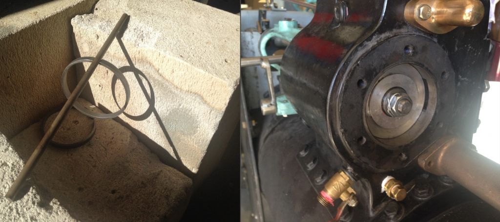
                  Piston rings were turned from a solid piece of cast iron round bar. A bore gauge used to accurately measure the cylinder and the rings made for a sliding fit. They were then parted with a Dremel grinder.

                  The rings were very tight when I tried fitting them in the cylinder. On checking the bore diameter, I found that the cylinder liner had been compressed at each end as a result of the heat/shrink fit with steam chest and had to be honed to the correct size.

                  2410 piston rings.jpg

                  The rings were cut with a grinding wheel on a Dremel leaving a 1mm gap.

                  Spring action in the rings made by expanding them over a piece of 6mm rod and evenly heating with a blow torch until they fell off, resulting an enlarged gap of 4-5mm.

                  2412 piston rings.jpg

                  #396925
                  Paul Lousick
                  Participant
                    @paullousick59116

                    The aluminium piston head was made in 2 parts to hold the 2 rings side by side in only one slot. The theory being that if the rings touch each other and the gaps are 180 degrees apart they will seal better. The width of the slot machined to match the width of the rings. 2401 piston head.jpg

                    The crosshead was made from a casting and is attached to a taper on the end of the piston rod in a matching tapered hole and secured with a wedge.

                    The bronze slippers were made from segments of old bushes. A machined slot on the underside of the slipper saddles the crosshead and 3 bolts hold each in place.

                    The end of the slippers was turned slightly larger than the trunk guide bore and the majority of metal removed on the mill. The turned surface used as a guide to how much to remove.

                    The holes were countersunk and assembled head turned to a slide fit with the crosshead.

                    2420 crosshead slipper.jpg

                    #397152
                    Paul Lousick
                    Participant
                      @paullousick59116

                      Stephensons Valve Linkage

                      The valve linkage was modelled in 3D to check clearances in all positions of its motion. Solidworks models can be automated and the crankshaft rotated which in turn moves the linkage arms and opens and closes the slide valve. The reversing lever can be moved to reverse the action of the slide valve. Very handy for checking slide valve/port overlap dimensions.

                      2500.jpg

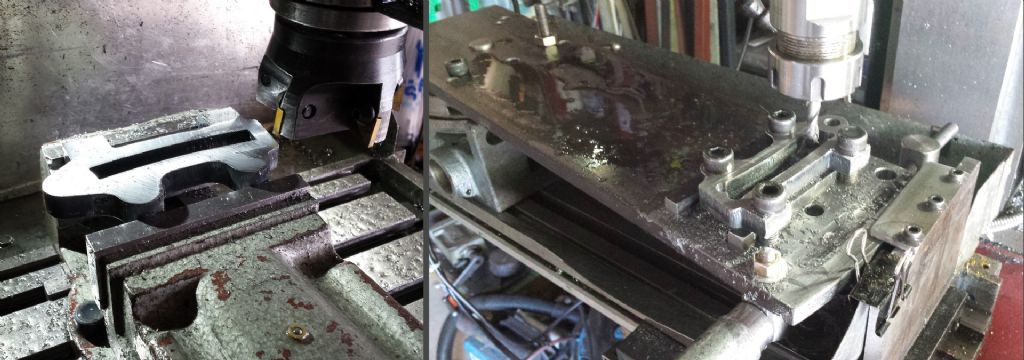
                      The quadrant link was laser cut from plate and faced on the mill to finish size then the holes for pivot pins drilled and reamed. A mounting plate to extend clamping face of the rotary table was made for holding the links. A CAD drawing with dimensions for the pivot point and for the hold-down bolts made the location of the link easy. With the axis of the RT set at 0,0 the required radius for the slot in the link could be made. The end of the mounting plate was held captive in a slideway, top and bottom and rotated by a lead screw at the end. (The radius was too big to rely on the worm in the RT).

                      2501.jpg

                      The middle piece made in a similar way but because of its smaller size and only one hole, I made it twice as long and cut it to length after machining.

                      2502.jpg

                      #397153
                      Paul Lousick
                      Participant
                        @paullousick59116

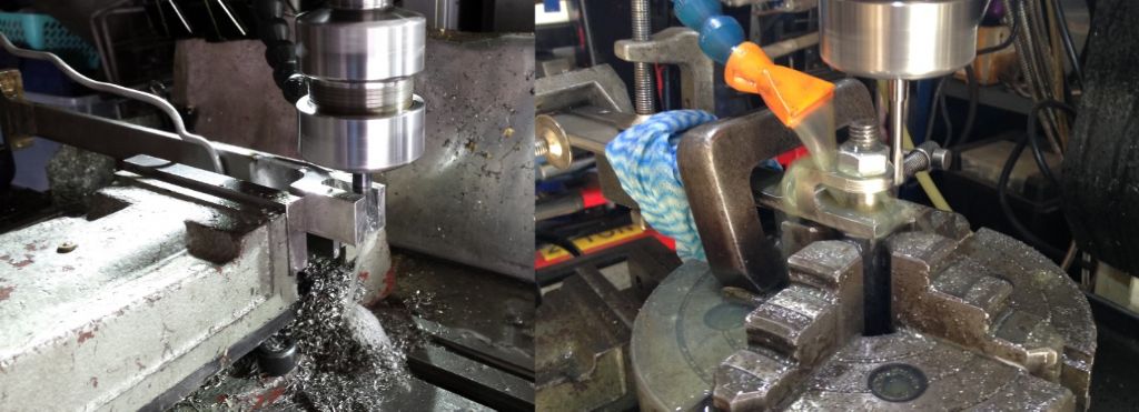
                        The control rods and levers for the valve control gear were fabricated from 316 S/S. (not the same as those on the original engine but they will not rust when left unpainted). The fixtures on the end of the rods were made slightly oversize to allow for any misalignment and machined to size after welding. Rounded ends done on a rotary table.

                        2503.jpg

                        Flat bar bent into a U-shape and a hole drilled in the end with a rota broach in the mill. A piece of round bar then welded to the end and turned to finish size. It was then reversed and the opposite side turned. Hole thru round bar drilled and reamed and bits not needed were removed

                        2504.jpg

                        Lifting levers also fabricated from flat and round bar and finished on the mill. A bull nose cutter used to create a fillet on some corners. Pivot pins and thick securing washers with a hole for split pin made.

                        2505.jpg

                        #399559
                        Paul Lousick
                        Participant
                          @paullousick59116

                          Compensating Centre

                          The compensating centre (differential) is normally made from a casting but this was missed when I ordered the other castings for my engine. The original order was sent to Australia by sea freight and the extra weight would not have increased the delivery by much. Sea freight cargo has to be sent in a large wooden box so it can be loaded by forklift. It also has to be fumigated making it expensive.

                          It is a large, heavy casting which sells for about £120 but would have cost another £160 for air freight. Too expensive, so I fabricated my own from plate and hollow bar.

                          2702 compensating centre welding.jpg

                          As well as designing a fabricated version of the hub, I modified the lubrication arrangement. In the original design, a pipe was used to carry oil to the drive gear bush and a hole in the casting to oil the pinion gear shaft. As the gears and bush rotate slowly, I prefer to use grease. Oil lubrication without shaft seals is messy and drips onto the ground. (and my driveway).

                          A hole in the centre of the pinion gear shaft carries grease to both bushes. Access to the grease nipple is thru the holes for the wheel locking pin. The pin is removed and outer gear rotated slightly to expose the grease nipple. The nipple also prevents the shaft from rotating.

                          2701.jpg

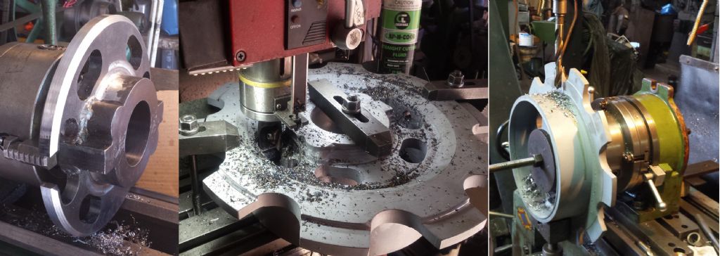
                          Left: Preliminary machining of hub prior to welding hollow bar, Middle: Final machining, Right: Drilling and reaming holes for bevel gear shaft

                          2703 compensating centre machining.jpg

                          #399560
                          Paul Lousick
                          Participant
                            @paullousick59116

                            Turning end of hollow bar for rope drum keeper plate. Boring holes in outer drive gear for wheel lock pins. Turning bronze bush for inner drive gear, 2704 pinion shaft.jpg

                            Turning wire rope drum casting. Drilling holes for rope drum locking pin. Fitting ring gear

                            2705 winch drum.jpg

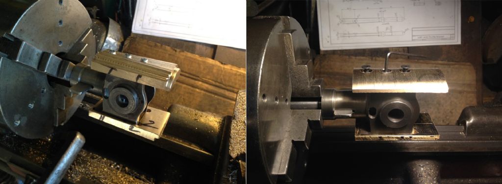
                            The gears were purchased as finished parts and were meant to operate without bearings. I decided to add a bronze bush. But how to hold it ? I bolted it to a piece of round bar and centred it in a 4-jaw chuck.

                            Pressed in a bush and faced it to length. 2706 pinion gear .jpg

                            Finished compensating centre assembly. 2707 shaft assy.jpg

                            #408214
                            Jon Cameron
                            Participant
                              @joncameron26580

                              Wow just been catching up with this thread. Superb work!!

                              Look forward to seeing it near completion😊

                            Viewing 13 posts - 51 through 63 (of 63 total)
                            • Please log in to reply to this topic. Registering is free and easy using the links on the menu at the top of this page.

                            Advert

                            Latest Replies

                            Home Forums Traction engines Topics

                            Viewing 25 topics - 1 through 25 (of 25 total)
                            Viewing 25 topics - 1 through 25 (of 25 total)

                            View full reply list.

                            Advert

                            Newsletter Sign-up