6″ Ruston Proctor Traction Engine – Model Build

Advert

6″ Ruston Proctor Traction Engine – Model Build

Home Forums Traction engines 6″ Ruston Proctor Traction Engine – Model Build

Viewing 25 posts - 26 through 50 (of 63 total)
  • Author
    Posts
  • #212965
    Neil Wyatt
    Moderator
      @neilwyatt

      Very clear post, Danny. Does the cross-arm on the valve have dimples for the cones on the valve bobbins?

      Neil

      Advert
      #212968
      Paul Lousick
      Participant
        @paullousick59116

        (Continued build log from part 1)

        MACHINING THE STEAM CHEST

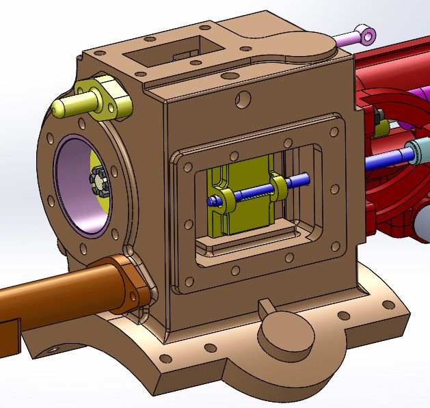
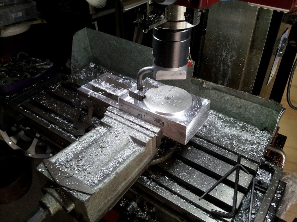
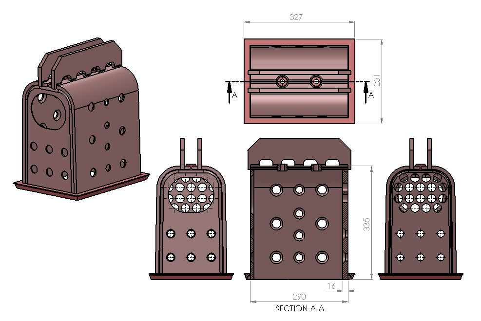
        The steam chest is the largest casting that was supplied by LSM and weighs 22 kg, and is probably the most complex piece to machine. It was also the most difficult measure to make a model in 3D. The drawings of the steam chest had dimensions for the machined surfaces and bolt holes but not for the other features of the casting. Attempting to measure the shape with a rule and straight edge was too difficult because of an accumulation of measuring errors and I was not happy with the outcome. I had just fitted a DRO to my SX3 mill and decided to use this for a more accurate solution. (The SX3 mill is just big enough to machine this size casting).

        0700 steam chest.jpg

        0701 milling end (medium).jpg

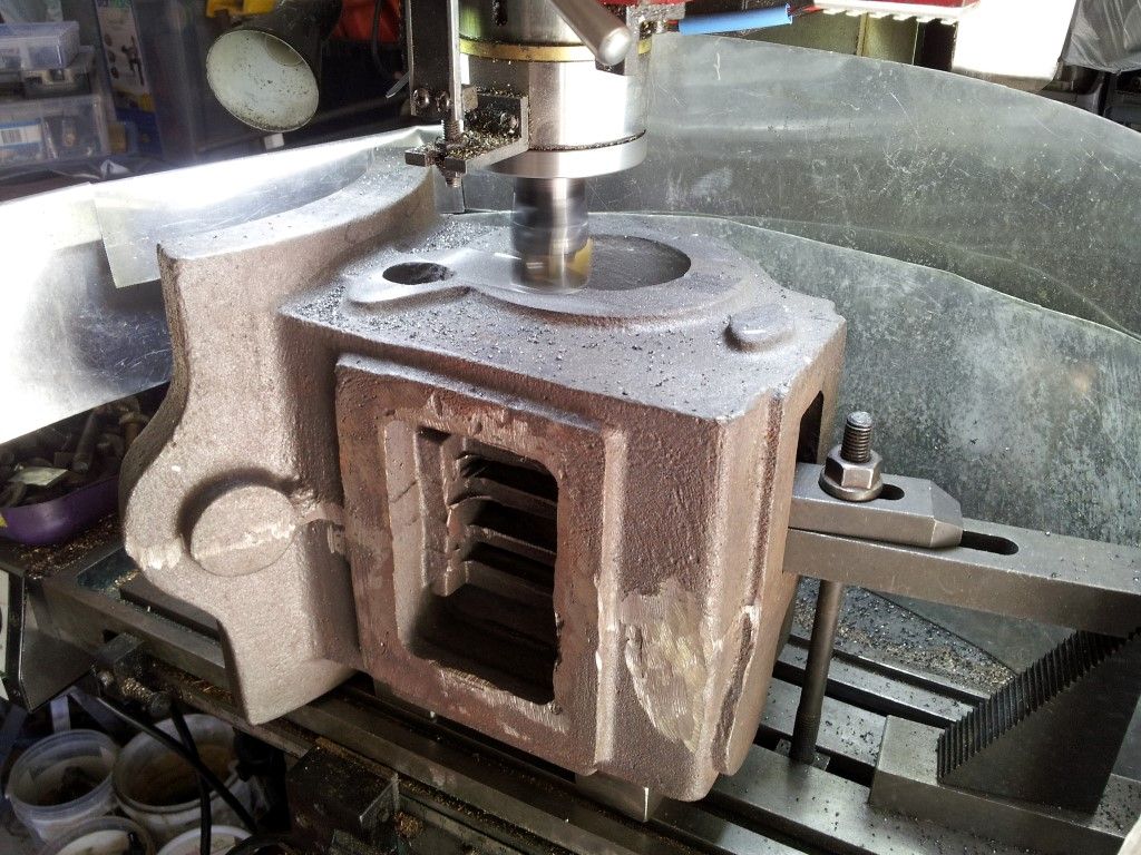
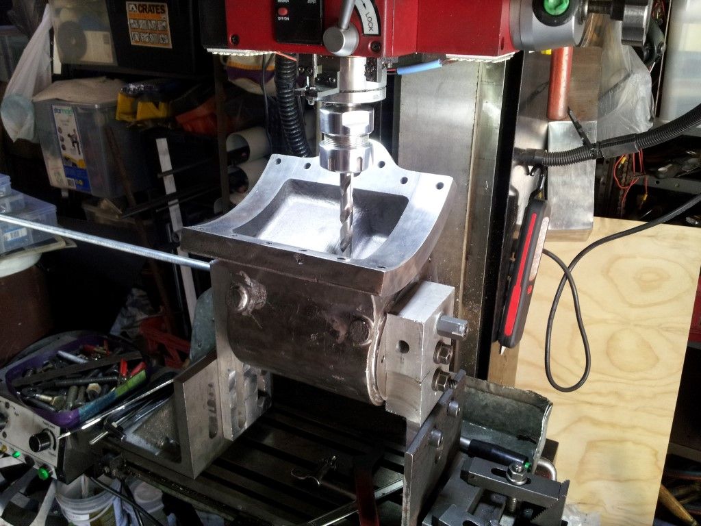
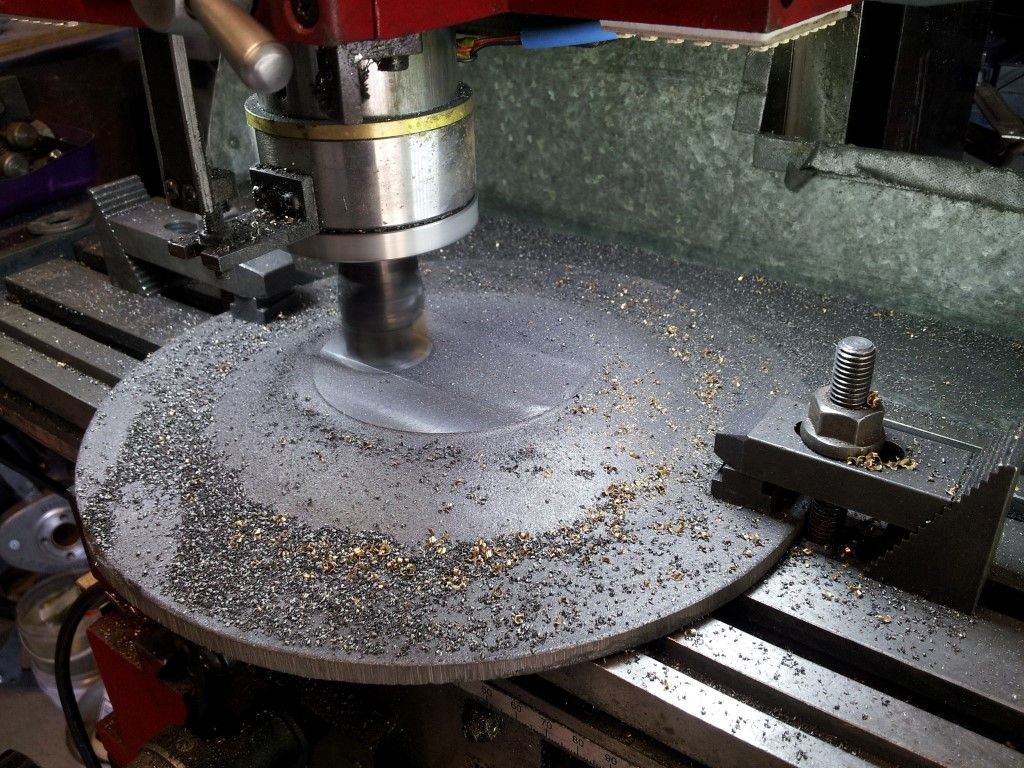
        MACHINING THE FIRST FACE OF THE CASTING

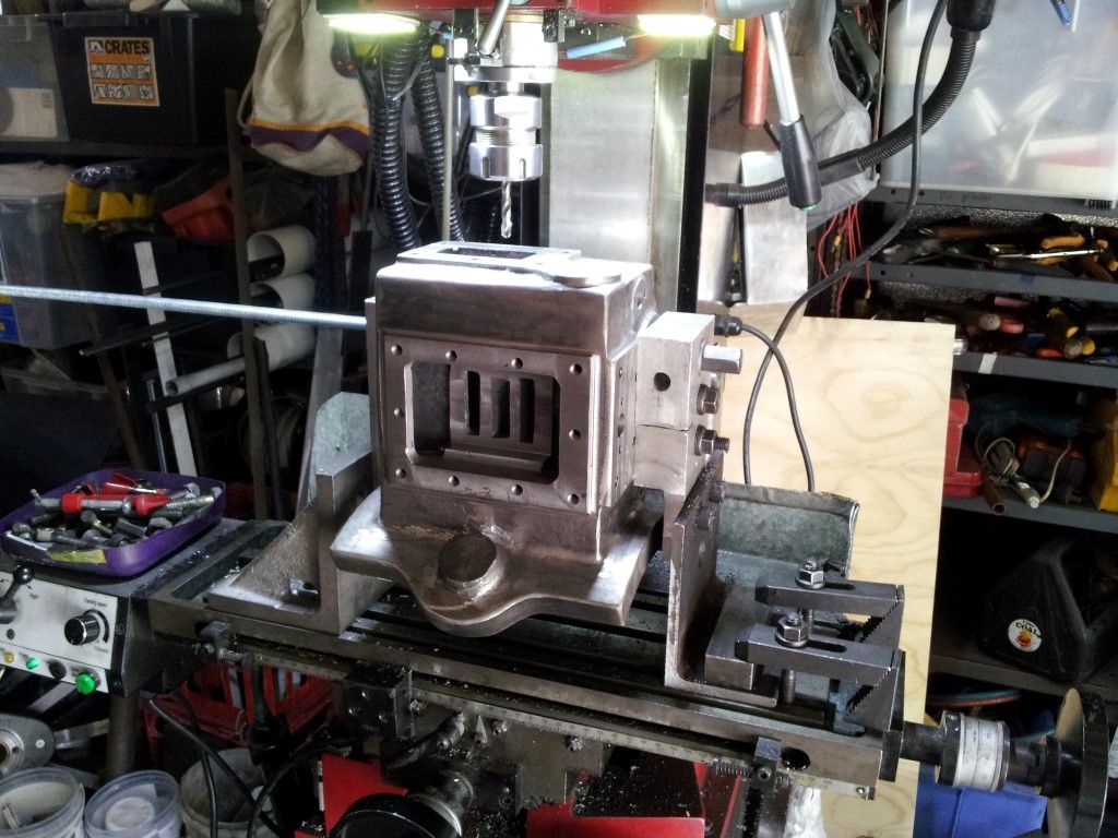
        Machining of the front surface of the steam chest casting using a 32mm cutter with replaceable carbide inserts. As this was a raw casting, there were no accurate faces to use as a datum for the milling setup and many double checks were made before settling on this position.

        0702 drilling tapping top (medium).jpg

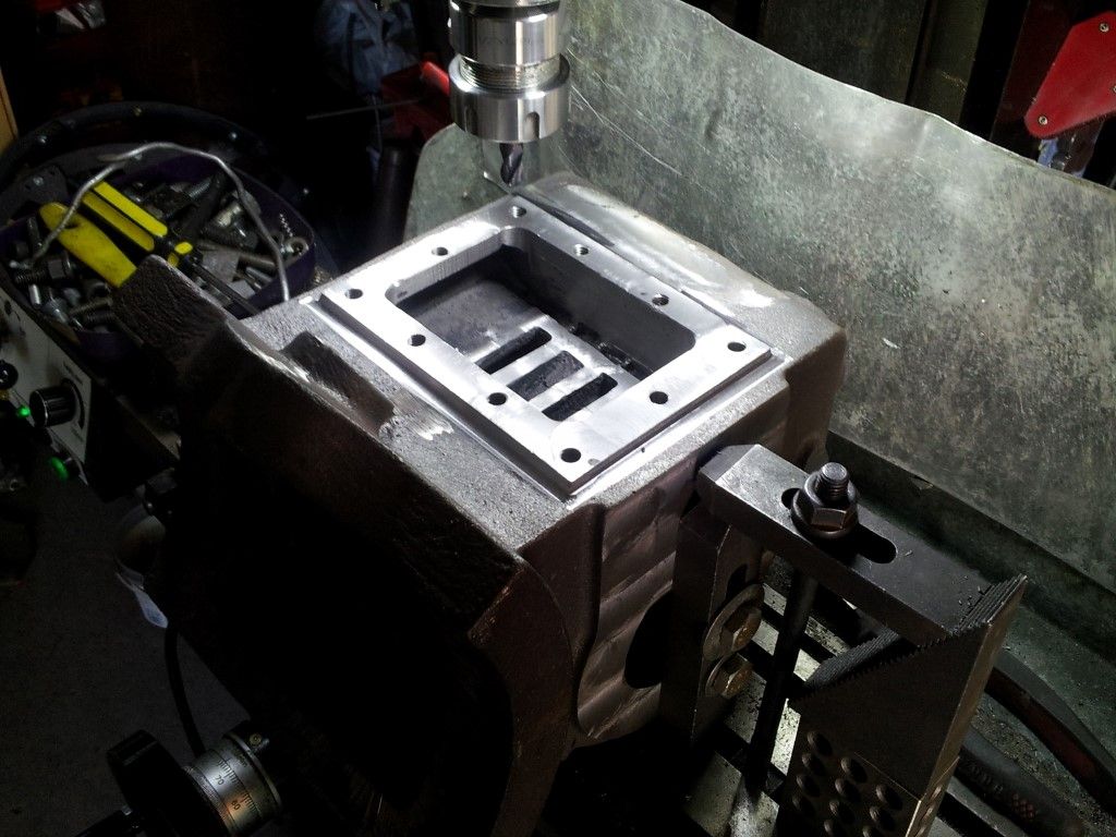
        MACHINING THE LEFT HAND SIDE OF THE CASTING

        The casting was turned on its side to machine the mounting face for the reverse valve cover and slide valve seat. Holes drilled and tapped for threaded studs which will hold a cover plate.

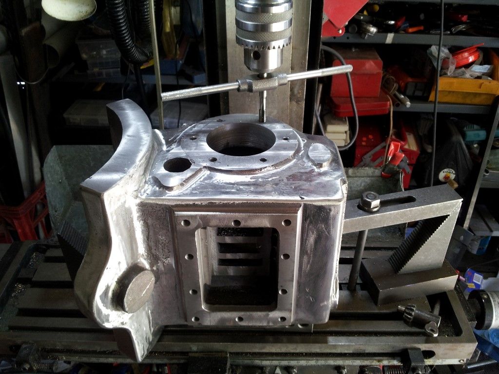
        0703 tapping ront (medium).jpg

        After cleaning up the casting with an angle grinder and a small hand held belt linisher, the front face was drilled and tapped for the front cover plate. These tapped holes would become a datum for cutting the bore in a later operation.

        0704 boring  (medium).jpg

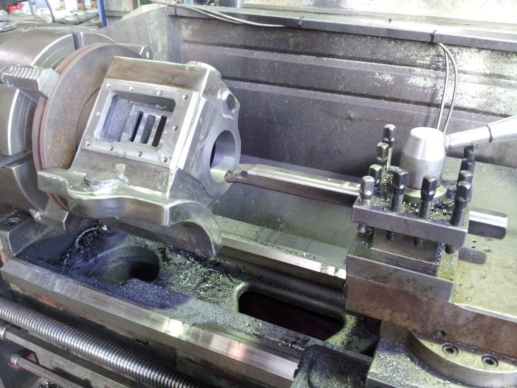
        My solution for holding the casting in the lathe was to use an old car brake disc as a face plate.

        The front side of the brake disc was flat and did not need machining, except for a slight ridge on the edge where the brake pads had not worn and I ground these off. Then clamped the disc to the top of the mill table and took a slight cut on the top surface to guarantee that it was parallel to the bottom. A series of mounting holes to match those on the front of the steam chest was next. The steam chest was bolted to the brake disk and held in the lathe chuck for facing the rear side of the casting and for boring the hole for the cylinder liner. The rear side hole was made slightly bigger than the front for ease of pressing in the cylinder liner. The rear end of the cylinder liner is slightly bigger than the front. Both ends will be a press fit into the steam chest.

        0705 milling base (medium).jpg

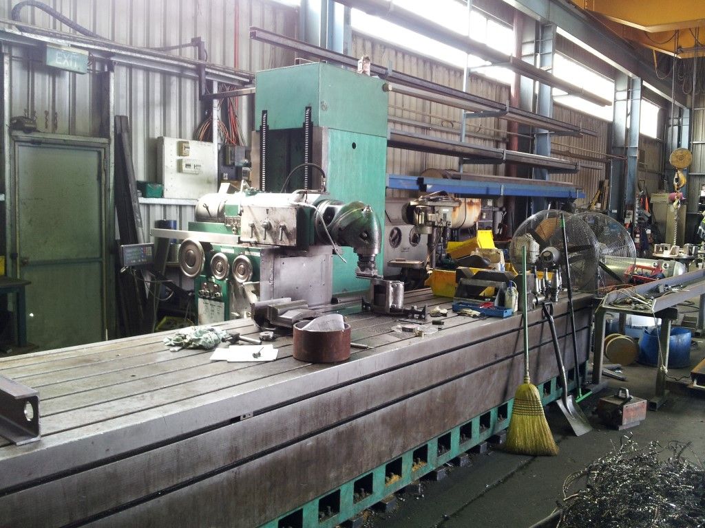
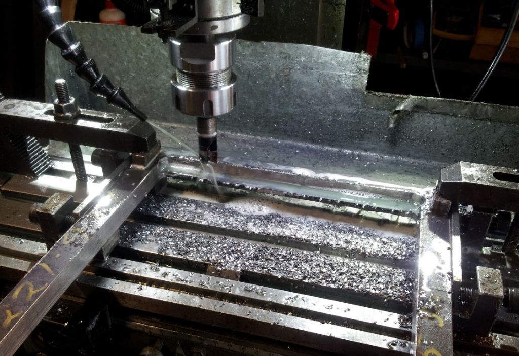
        Machining the bottom of the steam chest which bolts onto the top of the boiler in a BIG MILL. Normally the table is the part that moves, but on this mill it is stationary and the head moves. The steam chest is that little thing under the cutting head and the piece of 10” dia pipe in the middle of the picture is an offcut from the boiler barrel to use as a reference. I have allowed a 1mm gap between the boiler and steam chest for a gasket.


        0706 milling base 2 (medium).jpg

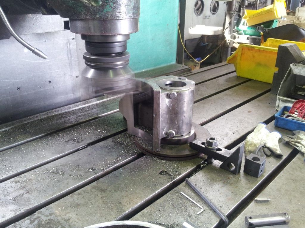
        The steam chest, still attached to the brake disc and clamped to the mill table.

        Mounting face of the steam chest being machined. We did not have a suitable cutter and first tried a HSS fly cutter but kept bluntening the tip on the cast iron. Then used a standard lathe tool with a carbide tip which worked well. Just had to run the mill in the reverse direction to suit the handing of the lathe tool.


        Edited By Paul Lousick on 18/11/2015 09:56:14

        Edited By Neil Wyatt on 19/11/2015 13:31:24

        #212969
        Paul Lousick
        Participant
          @paullousick59116

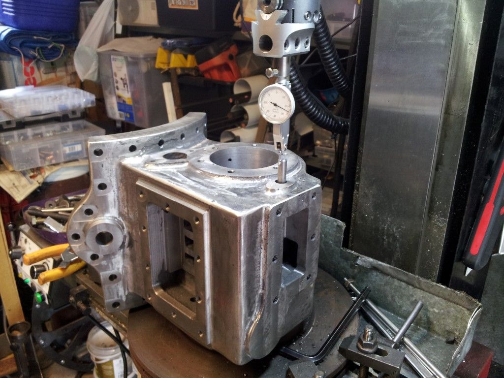
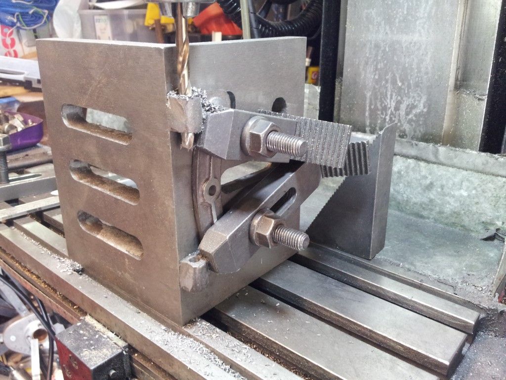
          SUPPORT JIG FOR FINAL MACHINING OF THE STEAM CHEST

          0707 jig (medium).jpg

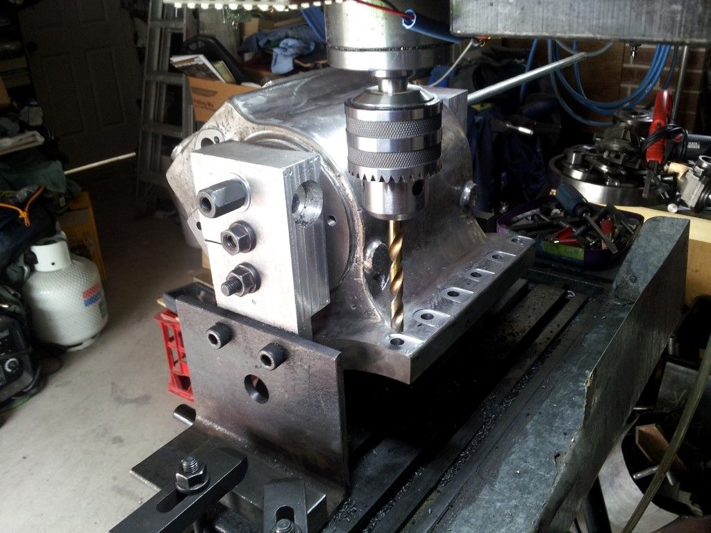
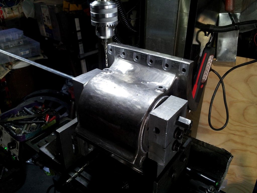
          Making a jig to support the steam chest by the cylinder bore while I machined the other faces and for drilling holes.

          0708 drilling top (medium).jpg

          The steam chest supported by the jig and able to be rotated about the bore axis. (Just fits on the mill)

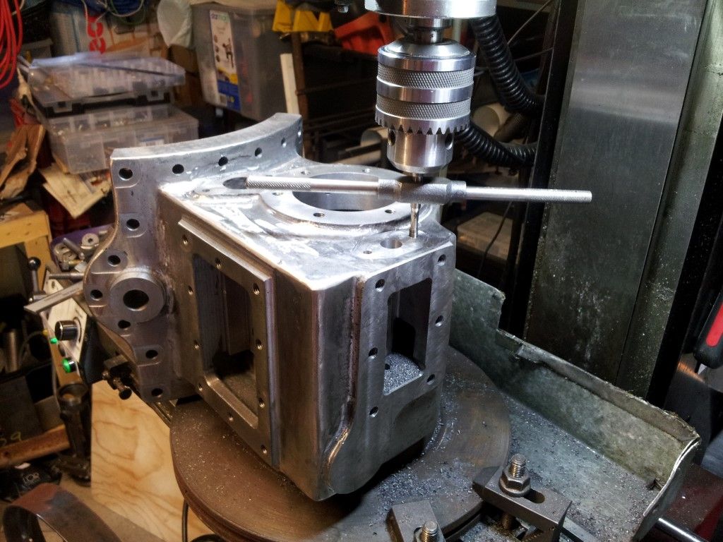
          0709 drilling mounting holes (medium).jpg

          The mounting holes have been faced and the holes are being drilled.

          0710 milling slide valve seat (medium).jpg

          Final machining of the slide valve.

          0711 drilling steam ports (medium).jpg

          Steam drain ports being drilled and tapped.

          0711b drilling steam port in bottom (medium).jpg

          Drilling steam port hole from the cavity in the casting base to a cavity around the cylinder lining.

          0712 locating hole (medium).jpg

          The regulator slide valve is mounted on a shaft which goes completely thru the steam chest and I did not have a drill long enough to drill completely thru from one side. My solution was to drill and ream the hole to size from the bottom side in the photo then turn it over and drill a bigger hole on the top side. (Fortunately the hole on this side is much bigger to accommodate a gland fitting). I then fitted a piece of bright bar in the bottom hole and found its center and opened up the hole with a boring bar.

          0713 tapping gland holes (medium).jpg

          There was a mistake in the casting and the boss (shown in the previous photo) was too small for the gland fitting. (supplied as a gunmetal casting). The solution was to mill it off completely and have a slight recess as shown.

          0714 side cover (medium).jpg

          Cover plate for the side of the steam chest. Holes still to be drilled

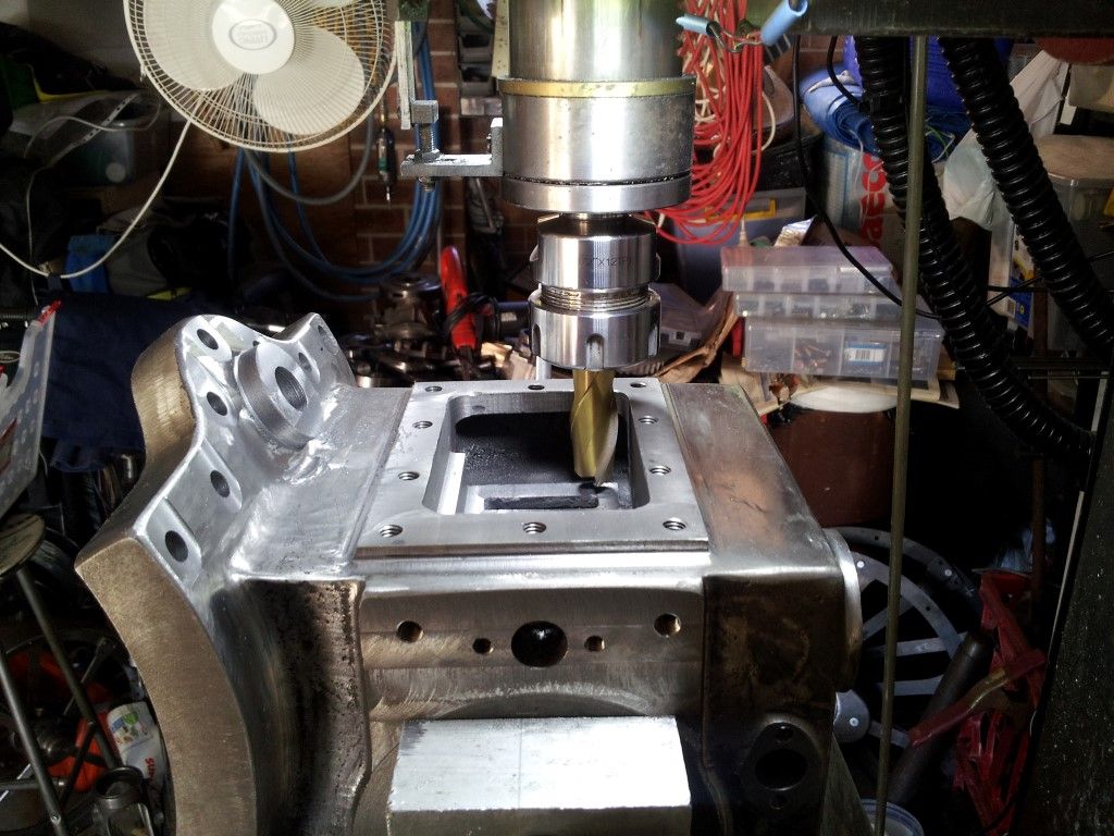
          0715 front cover (medium).jpg

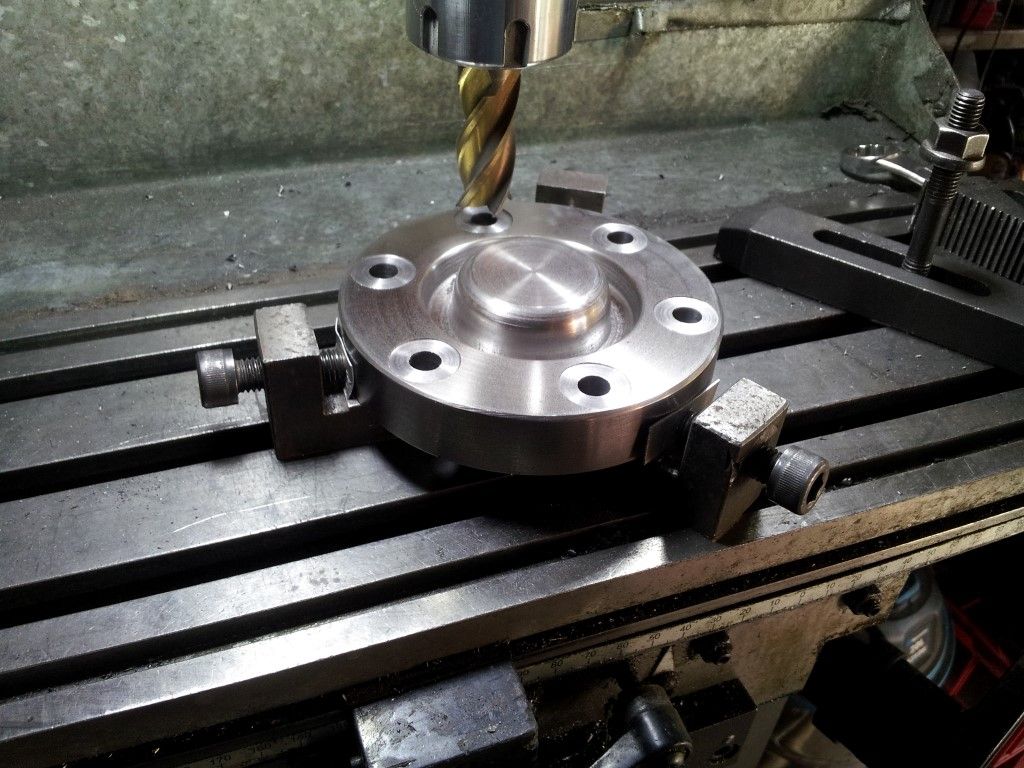
          Cover for the front of the cylinder liner. The supplied cast iron casting was firstly turned and polished on the lathe before drilling the holes. The spotface made by plunge cutting with an end mill. Although not completely flat because of the shape of the end of the cutter, they will be OK.

          Edited By Neil Wyatt on 19/11/2015 13:32:11

          #212981
          Paul Lousick
          Participant
            @paullousick59116

            Hi Neil,

            Who is Danny ?

            With my last addition to my build post, I got a message that I had exceeded the allowable size, started a second thread.

            What is the file size limit ?

            Paul.

            #213139
            Paul Lousick
            Participant
              @paullousick59116

              TRUNK GUIDE

              The trunk guide attaches to the rear side of the steam chest and guides the piston cross-slide, keeping the piston on center with the cylinder liner. Fitted inside the guide at the steam chest end is a shaft packing gland which seals the piston rod to stop steam from escaping.

              Below the trunk guide is a mounting plate which supports the control lever shaft for the Stephenson reversing assembly.

              100 trunk guide (medium).jpg


              101 turning an a mandrel (medium).jpg

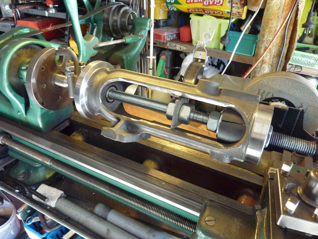
              The trunk guide casting was cleaned up with an angle grinder and a small hand held belt sander then mounted on a mandrel made from a piece of threaded bar. Cone shaped wedges located the guide on center with the holes in the casting and a lathe dog clamped to the mandrel for turning. The cutting tool caused the casting to slip on the mandrel so I added a drive plate in the middle to turn the casting.

              102 milling  (medium).jpg

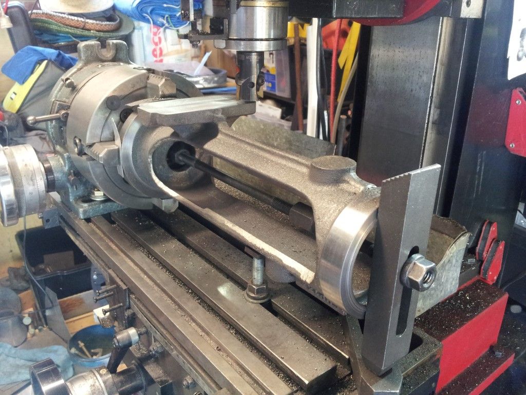
              Trunk guide mounted in a chuck on a rotary table for machining the bottom plate and oil drain.

              Note: The cross slide is drip-fed with oil from a small reservoir on top and has to be drained or will splash everywhere. In full size engines the oil just runs onto the ground but I will add a small tray to collect it (and save my driveway).

              103 turning trunk guide (medium).jpg

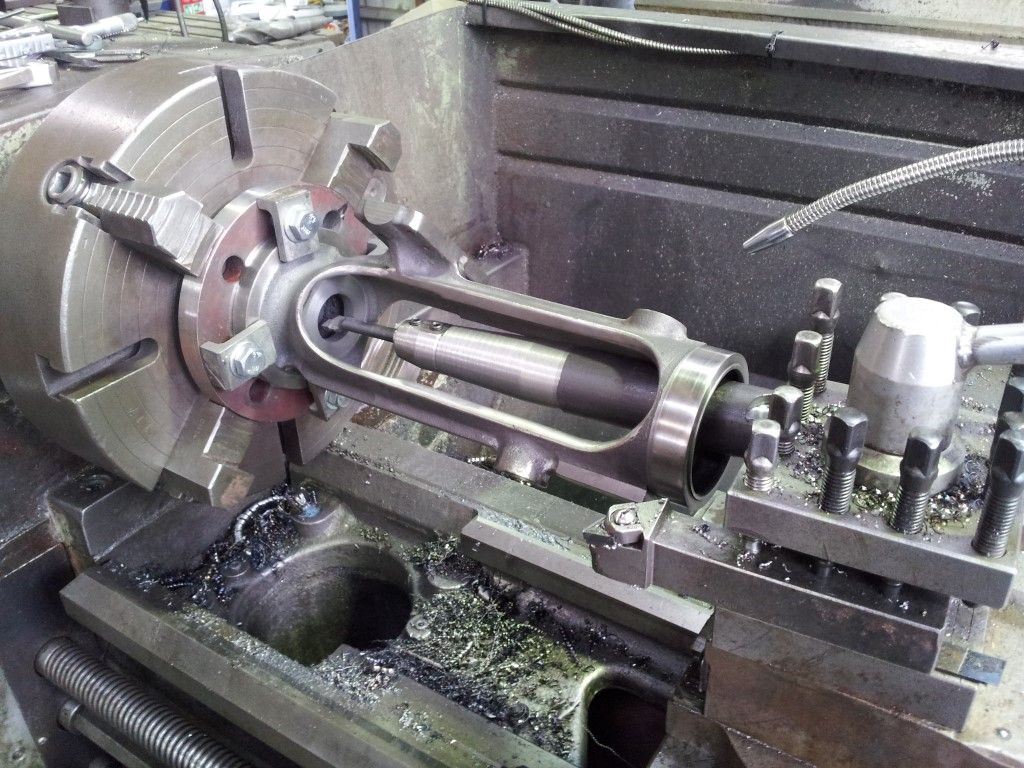
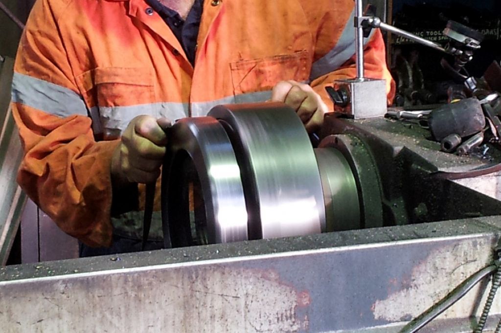
              The trunk guide has a spigot on the mounting end which locates on the bore of the cylinder liner but this was too narrow to hold such a long part in a lathe chuck. Instead I clamped a 6” dia steel disc in the chuck (an old pipe flange), took a slight cut on the front to face it and opened the bore up for a tight fit with the trunk guide. Then clamped the guide to it. The tail end also supported on the lathe for extra rigidity. The internal diameter then bored to size.

              104 facing gland face (medium).jpg

              I had to make a special tool for cutting the internal face of the casting and boring a hole where the piston stuffing box is fitted. CAD was used to layout and draw the special tool which holds a small carbide boring bar. One that I use on the boring head on my mill.


              Edited By Paul Lousick on 19/11/2015 08:54:14

              Edited By Neil Wyatt on 19/11/2015 13:32:28

              #213177
              Neil Wyatt
              Moderator
                @neilwyatt

                Hello Paul,

                You exceeded the size for individual messages, overall thread length is unlimited (I think).

                I have sewn the two threads back together.

                Thanks for persevering

                Neil

                #213249
                Paul Lousick
                Participant
                  @paullousick59116

                  SMOKE BOX DOOR – It is mounted on the front of the engine and provides access to the front of the boiler for inspection purposes and for cleaning the inside of the heating tubes. Regular cleaning is necessary to for the efficient heating of the water to make steam.

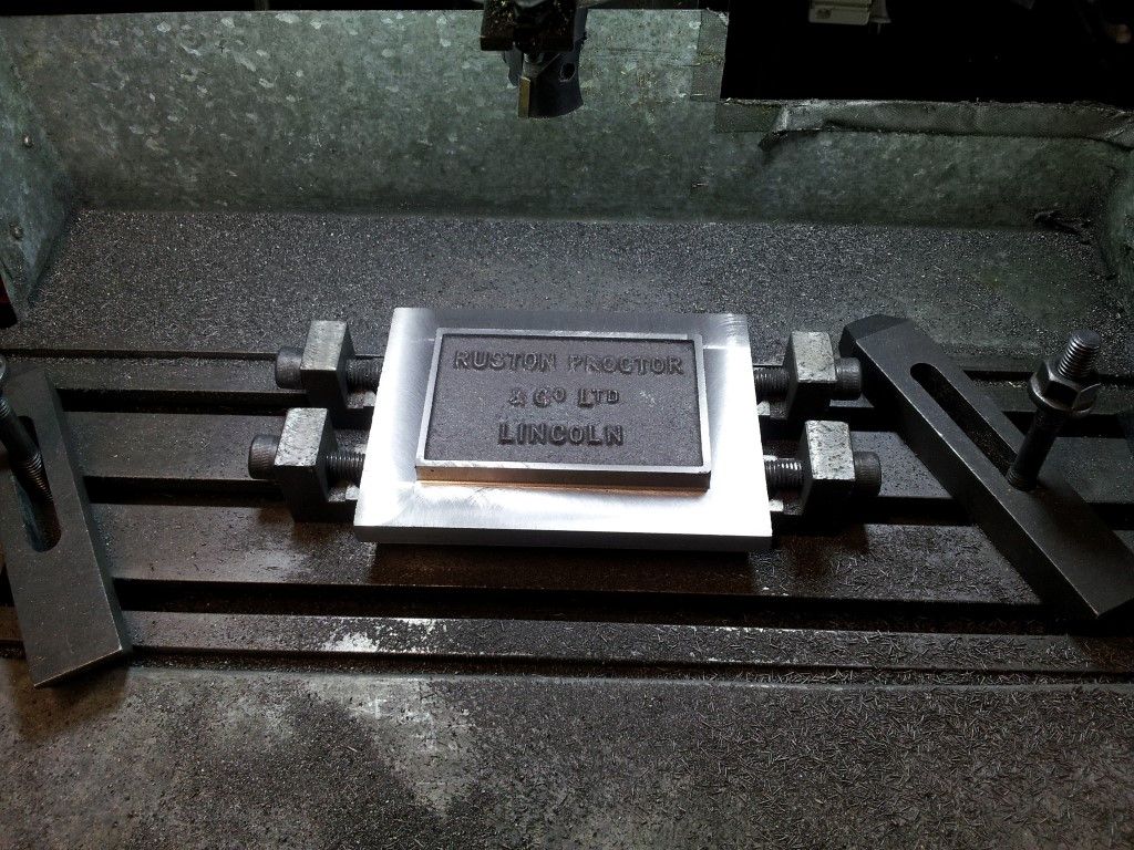
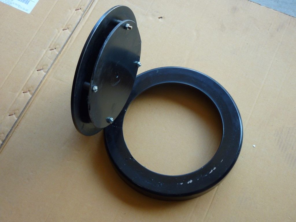
                  The outer housing for the smoke box door was supplied as a heavy cast ring, a casting for the door itself and a cast nameplate for the front of the boiler.

                  1101 milling face side (medium).jpg

                  The front face of the smoke box door being milled flat, then bolt holes were drilled for attaching the name plate casting.

                  1102 door hinge (medium).jpg

                  The door hinge has been faced on the rear side and mounting holes drilled for securing with rivets to the front of the door. It is shown here being drilled for the hinge pivot pins.

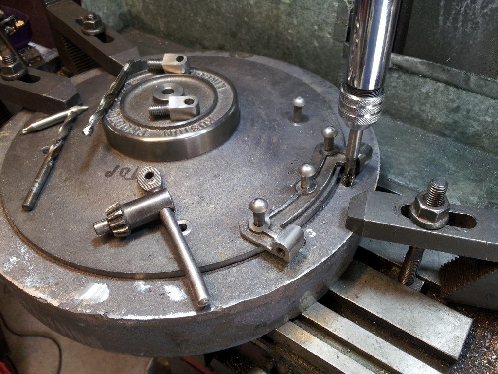
                  1103 name plate (medium).jpg

                  The OD of the name plate has been machined and the center boss face cut on the lathe. Hole being drilled for a bolt to hold the door in the closed position on the boiler.

                  1105 temp assembly (medium).jpg

                  Trial assembly of the door and tapping of the holes for the hinge blocks.

                  1107 machining casting  (medium).jpg

                  Door support ring on a lathe, turned to size and a radius cut on the outer corner.

                  1108 finished door (medium).jpg

                  1109 open door (medium).jpg

                  Final assembly of the support ring and the door. The bolts holding the heat shield will be replaced with rivets.

                  #213698
                  Paul Lousick
                  Participant
                    @paullousick59116

                    MODEL BOILER DESIGN and MANUFACTURE

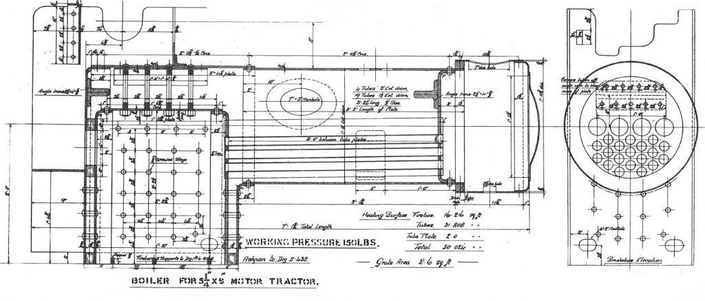
                    1201 original boiler (medium).jpg

                    Boiler design for the original traction engine

                    The boiler on the original full size traction engine was 20” OD x 85” (508 OD x 2160mm) overall length.

                    Boiler wall thickness: ½”

                    Distance between tube plates: 36”

                    Fire tubes: 4 x 3” dia and 19 x 1.5” dia.


                    1202 model boiler (medium).jpg

                    Boiler for 6” scale model boiler

                    The drawing for the model boiler specified a 10” OD x ¼” thick steel plate but 10” OD (254mm) is not a standard pipe size and the Australian Miniature Boiler Safety Code specifies that I use ASTM A 106 grade with a wall thickness of not less than 6mm.

                    I chose to use 10” NB schedule 40 pipe which is the standard commercial size and is 273.1mm OD x 9.27mm wall thickness. Flat boiler plates are 10mm thick.

                    Because the barrel diameter is bigger than that shown on the model drawings, everything else had to be made wider. The crankshaft has to be made slightly longer and because the hornplates are further apart, the rear axle is also longer.


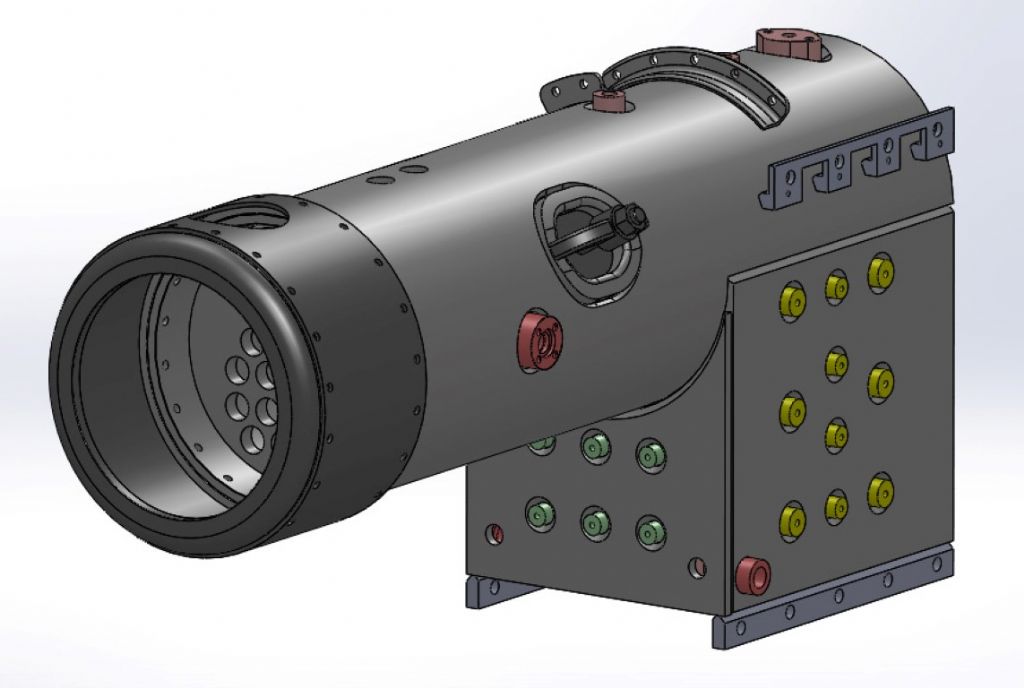
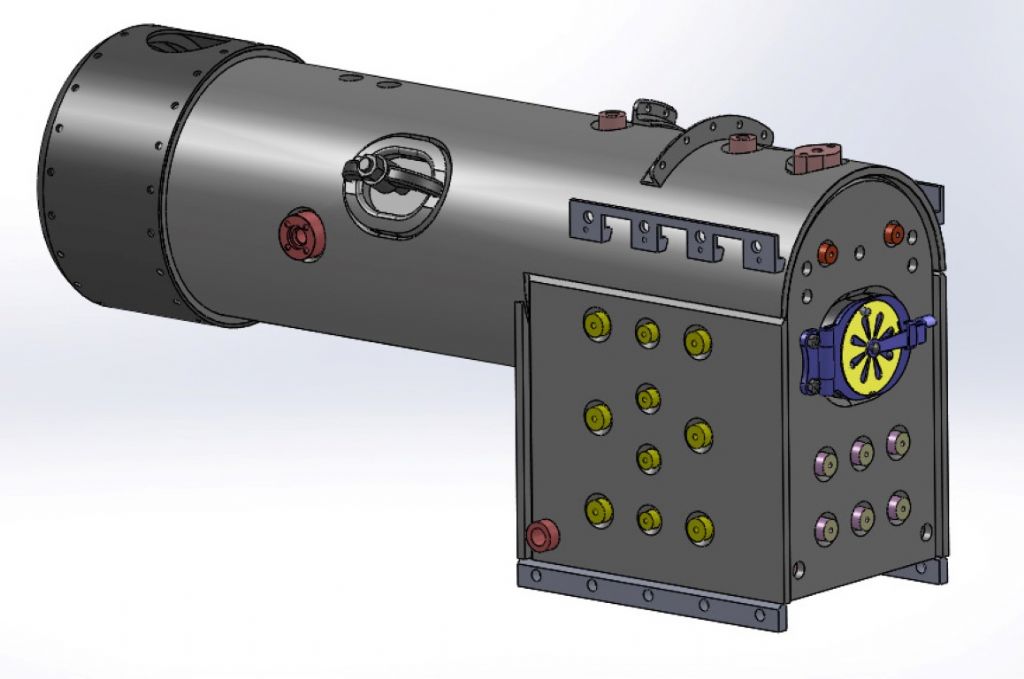
                    1205 boiler (medium).jpg

                    1206 boiler (medium).jpg

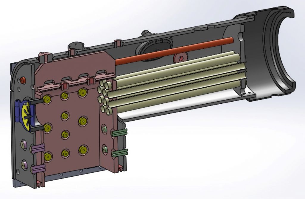
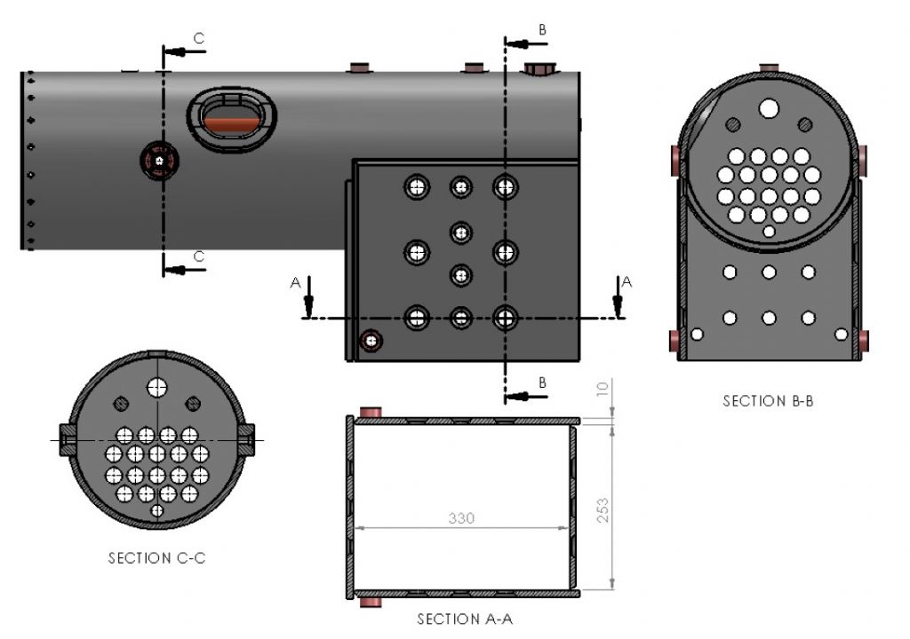
                    3D Models of 6” Scale Boiler created with Solidworks


                    1207 boiler (medium).jpg

                    Sectional View of Boiler


                    1210 machining barrel (medium).jpg

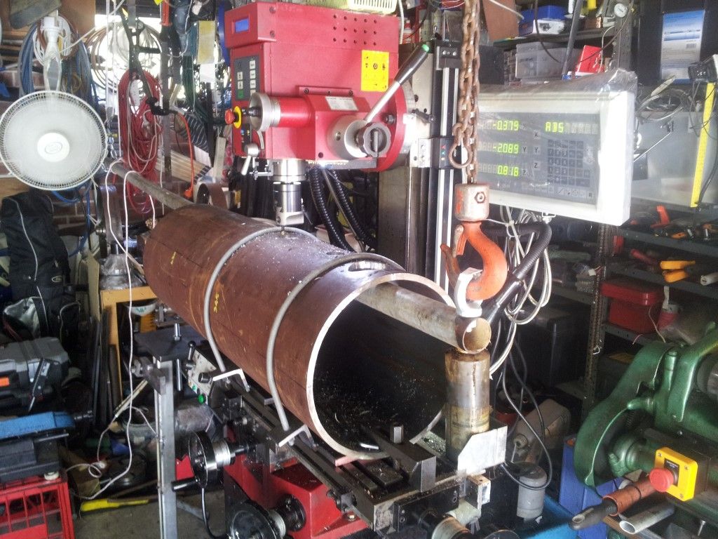
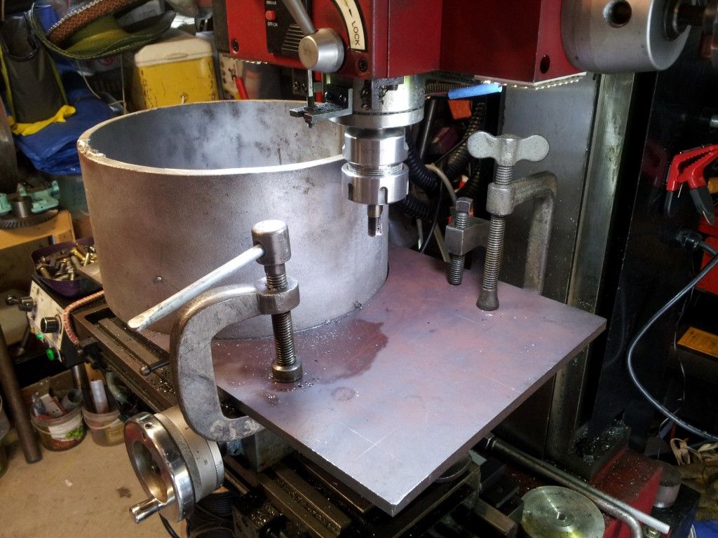
                    The boiler barrel was supported by a piece of pipe and held at both ends to take the load off the table of my SX3 mill while I machined holes for steam & water ports and for the manhole opening.

                    There was just enough space under the milling head for this operation and the sliding table is too small to carry such a big load.


                    1211 drilling holes (medium).jpg

                    Each hole was roughly cut to shape with a rotary broach cutter.


                    1212 boring hole (medium).jpg

                    Holes in boiler being bored to their finished size.


                    1213 cutting barrel (medium).jpg

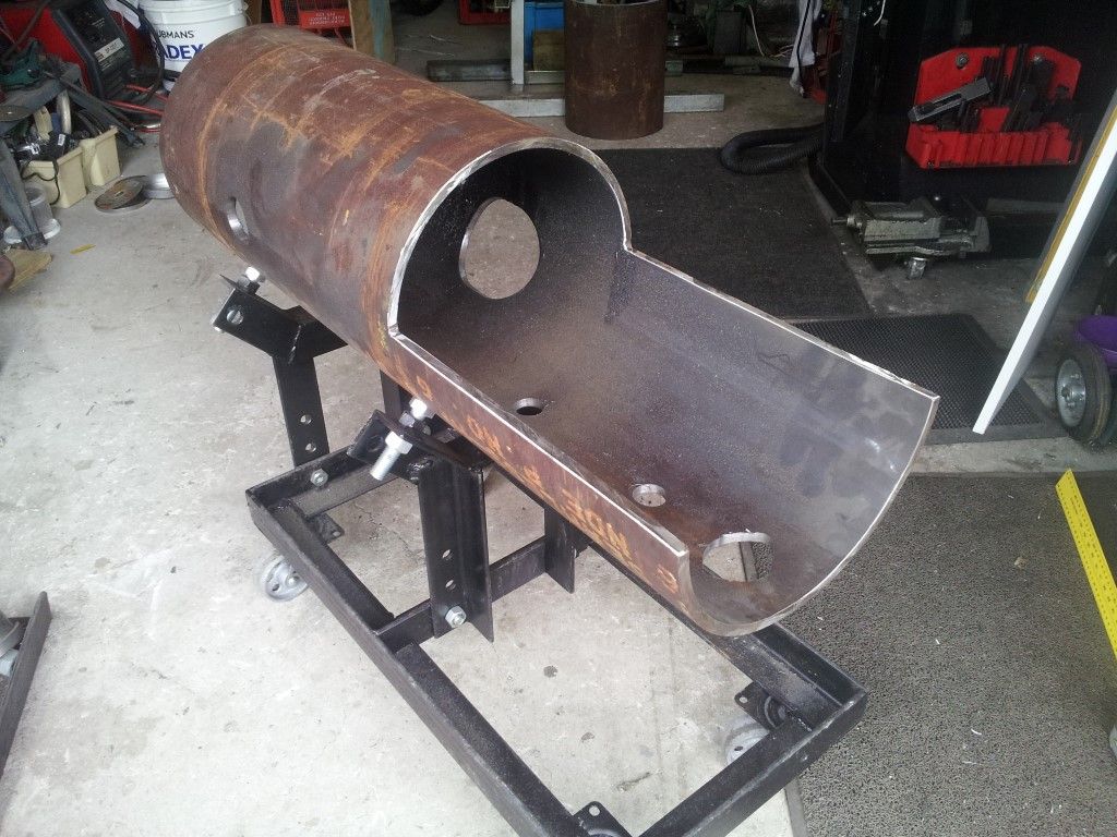
                    Boiler barrel mounted on a specially made trolley which is used for the assembly of the boiler.

                    The barrel is at the height of the finished engine and can be rotated on the trolley for different assembly operations. It is shown in this view after being trimmed for the firebox plates. The cuts were made with a 1mm blade in an angle grinder.


                    1214 gringing manhole (medium).jpg

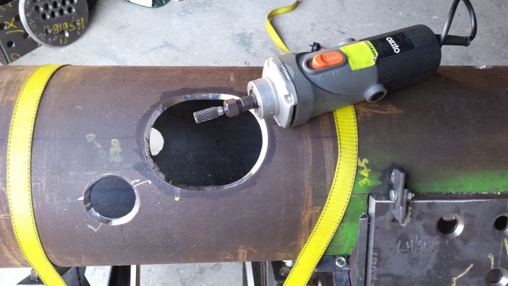
                    Weld preparations cut by hand with a carbide rotary burr in the chuck of wood router.

                    I found the router in the bargain bin of my local hardware store, less its accessories for $15. It has an 800 watt, variable speed motor that spins up to 22,000 rpm and easily cuts thru steel plate.

                    Edited By Paul Lousick on 23/11/2015 08:44:22

                    #214063
                    Paul Lousick
                    Participant
                      @paullousick59116

                      BOILER FABRICATION

                      1216 boiler (medium).jpg

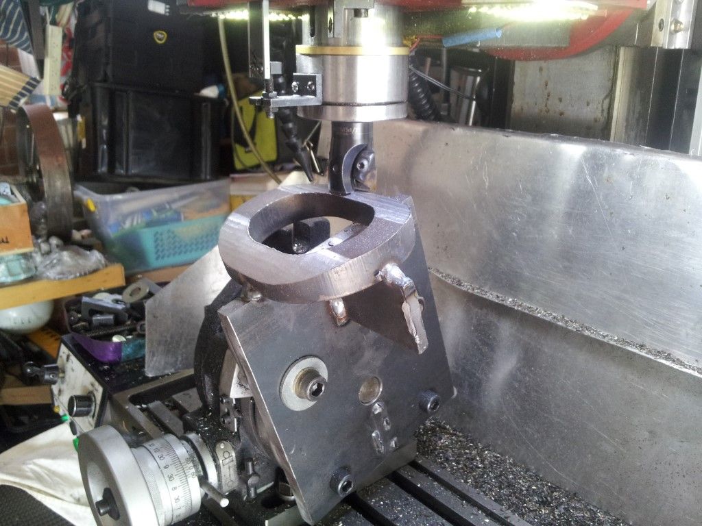
                      The pieces of plate which make up the boiler were plasma cut from boiler plate (460 MPa steel) and machined to the finished size on my SX3 mill. All joints for the plates are full penetration welds and have to be made by a certified welding operator and beyond the capabilities of myself. That will be done by someone more qualified. The weld preparation is a combination of bevel welds and “J” shaped welds.

                      Bevel welds are far easier to machine (or grind) and “J” welds much harder. The advantage of “J” shape weld preparation is that they are more compact and the cut is not as wide.


                      1217 boiler firebox plate (medium) (medium).jpg

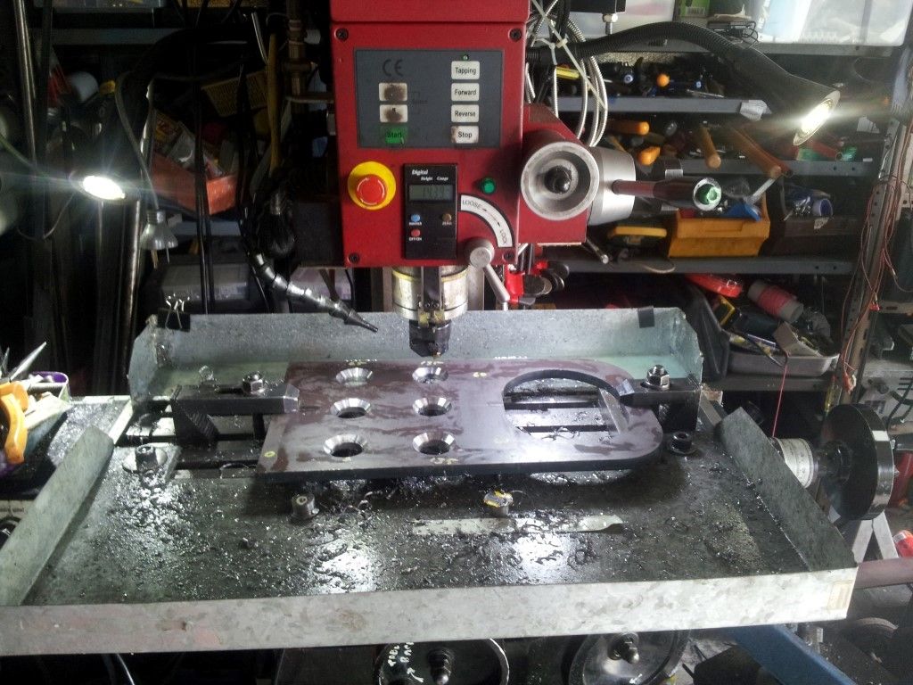
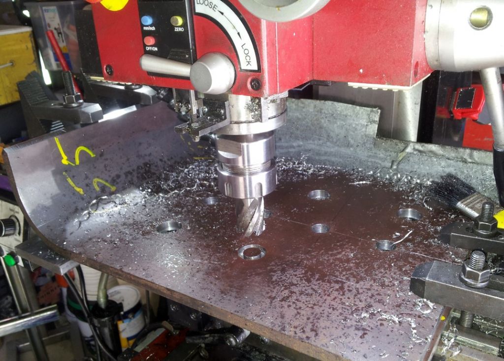
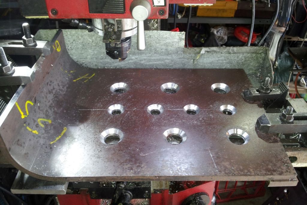
                      The holes for the firebox wall stays were cut with a rotary broach, held by a collet in the mill and then chamfered for welding in of the firebox stays.


                      1218 boiler firebox plate chamfer (medium) (medium).jpg

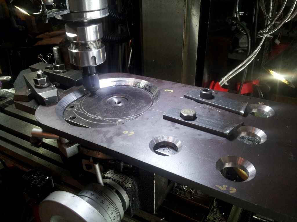
                      The rear plate of the boiler is mounted on a rotary table and a full depth chamfer is being milled leaving a 1.5mm flat on the bottom of the hole of the firebox opening. The exact location for the centers of the each side of the hole is not that critical and was done so "by eye" to line up with the circles which I scribed on the mounting plate below.


                      1219 firebox plate edge prep (medium).jpg

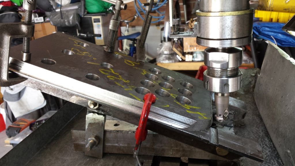
                      The boiler rear plate is supported at 20 degrees by a jig and is being milled by a cutter with a round insert which will produce the shape required for the “J” weld preparation on the edge. (Note: My milling machine can only rotate in the sideways direction and need this support for an inclined cut in the other direction.)


                      1220 boiler front plate (medium).jpg

                      Front boiler plate on a rotary table and being milled to clean up the profiled plate. A fillet weld preparation on the edge was cut after this one.


                      1221  fitting boiler front plate (medium).jpg

                      Checking the fit with a piece of boiler tube allowing for a 1.5m gap between the pipe and the plate. The 1.5mm gap is required for a full penetration joint when it is welded.


                      1222 boiler side plate (medium).jpg

                      Boiler side plates being machined to final overall size. And drilling holes for the firebox stays.

                      I aligned the first edge of the plate to be cut and made a clean-up cut then accurately rotated the plate to clean-up the second edge. Then used these 2 edges as datum to machine the remaining edges. The 2 datum edges were then used to mark the positions for the holes using the DRO on the mill. Then double checked all dimensions before cutting the holes. (I have learnt the hard way that it is good practice to measure twice before cutting once. Or having to cut twice if you do it wrong).

                      Edited By Paul Lousick on 25/11/2015 11:41:08

                      #214064
                      Paul Lousick
                      Participant
                        @paullousick59116

                        1223 smoke box tube plate (medium) (medium).jpg

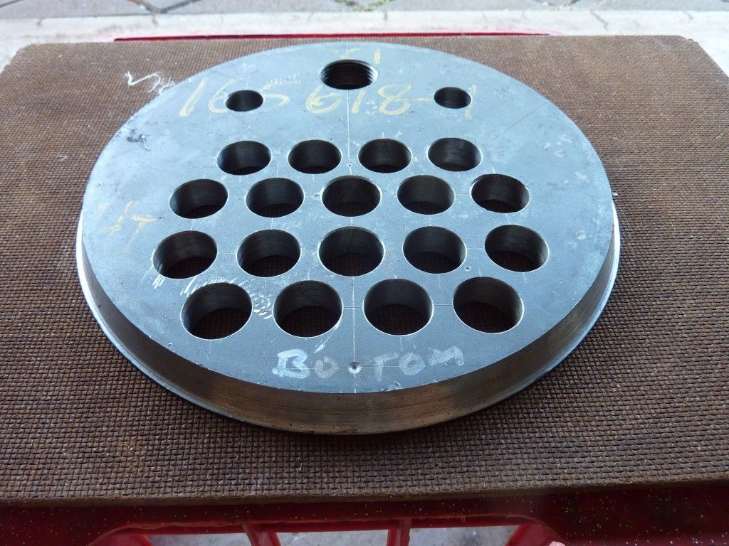
                        The front tube plate was supplied at the correct diameter to fit the inside of the boiler barrel and did not need machining. It is being drilled here for the fire tube holes and for an inspection hole at the top and 2 x holes for boiler stays beneath. A smaller inspection hole will be drilled at the bottom after it has been welded into the barrel, it is too close to the edge of the plate and may distort from the welding heat if it is drilled here.

                        1224 smoke box tube plate (medium).jpg

                        The plate was positioned on the center of my rotary table for cutting a “J” shape weld preparation on the edge because there is not enough space between the tube hole and the edge of the plate for a bevel weld.

                        The milling head was rotated by 20 degrees to produce the shape and cut with a round head cutter to make a radiused cut at the bottom.

                        The plate is 16mm thick boiler plate and a bit tougher than mild steel to cut. This put a big load on my mill and especially the rotary table. The small tables only use a small screw and the teeth cut into the worm gear are less than 2mm deep. The repeated impact of the cutter on this plate broke some of the teeth. F #%%%$####*&&&##

                        1225 manhole ring (medium).jpg

                        The support ring for the manhole opening had to be machined to suit the outside radius of the boiler. The inside surface that is used to seal against the manhole cover is normally curved to match the shape of the boiler barrel but this one is flat on the inside making it easier to seat against the cover . I laid it out on the computer to determine the necessary radius and fabricated a support jig for mounting it on my rotary table. (This was after I broke off some of the teeth so selected an area which still was intact.)

                        #214362
                        Paul Lousick
                        Participant
                          @paullousick59116

                          2026 manhole (medium).jpg

                          Detail of the boiler manhole and support ring. The surface of the inner surface of the support ring is flat and not curved as normally found in conventional boiler designs. Although it will protrude slightly into the inside of the boiler, it provides a better surface to seal and makes the manufacture of the manhole much easier.


                          2030 firebox .jpg

                          The steel plates for the inner fire box were profile cut from boiler plate and machined on my SX3 mill in my home workshop. The side plates were sent to a commercial company for bending in a CNC machine which produced the required radius and bend angle. The sides were made as 2 separate pieces because it is too difficult to bend a “U” shape accurately and maintain the required dimensions.


                          2031 firebox side (medium).jpg

                          The height of the plate was milled to correct size and the edge machined for a weld preparation.
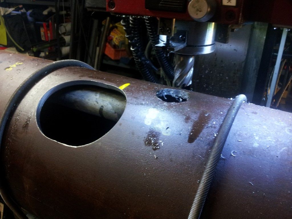
                           

                          2033 cuttinf holes for stays (medium).jpg

                          Cutting holes for boiler firebox side stays with a rotary broach.


                          2032 drilling firebox side (medium).jpg

                          Cutting holes for boiler firebox side stays with a rotary broach


                          2034 countersink for welding (medium).jpg

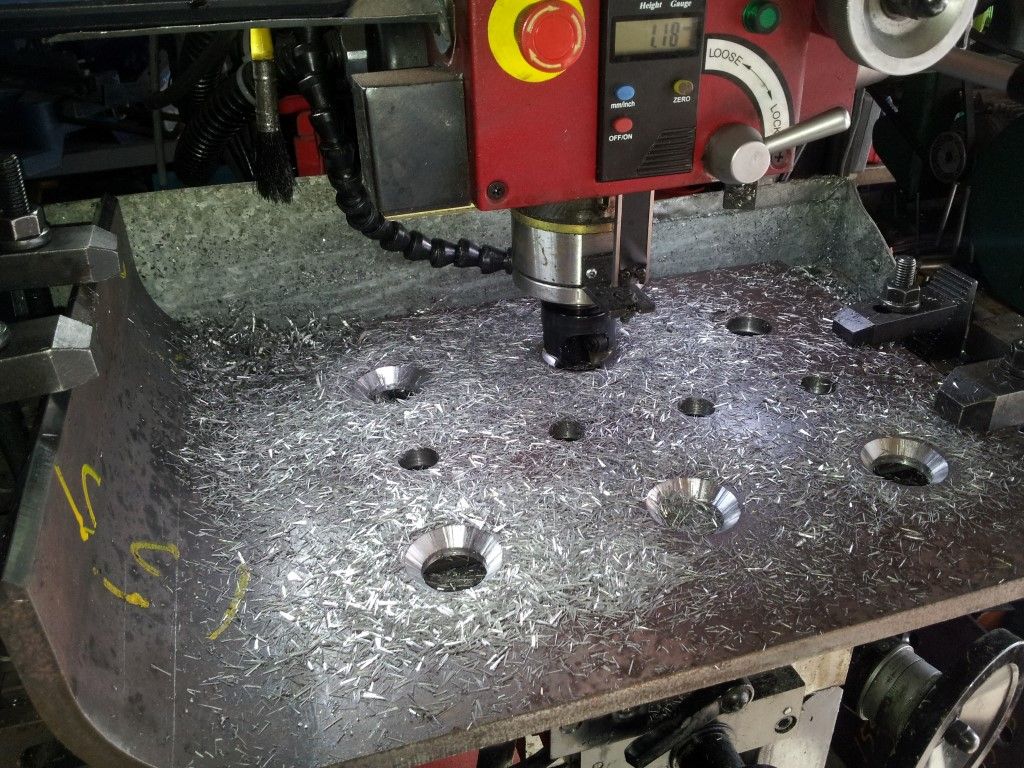
                          Countersinking holes for weld preparation.
                           

                          2035 firebox tube plate (medium).jpg

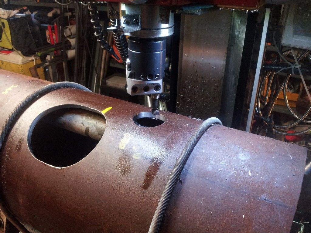
                          The holes for the fire tubes were drilled slightly undersize and will be reamed after welding for a slide fit with the tubes. The tubes will then be swaged with a special tool to expand them and create a steam tight seal. The initial pressure test for the seal will be twice the designed working pressure of the boiler.
                           

                          2036 firebox tube plate edge prep (medium).jpg

                          Milling a “J” shaped weld prep on the outer edges of the tube plate.


                          2037 machining foundation ring (medium).jpg

                          The foundation ring for the bottom of the fire box being machined to the finish size.


                          2038 foundation ring (medium).jpg

                          The boiler foundation ring has been machined with a “J” shape weld on the inside and the outside. It is too narrow for a standard bevel weld on both sides.


                          2039 fire box girder stays (medium).jpg

                          Firebox crown stays were profile cut and only needed a slight clean-up.


                          2040 fire box assy (medium).jpg

                          The assembly of the firebox. Now ready for welding and inspection before it is finally welded into the boiler.


                          2041 fire box supports (medium).jpg

                          View of the inside of the fire box showing the temporary support brackets that are tack welded to the plates. The brackets are bolted together, allowing me to dis-assemble the plates if required for additional machining.


                          Edited By Paul Lousick on 28/11/2015 08:48:38

                          #214366
                          Paul Lousick
                          Participant
                            @paullousick59116

                            2050 assembly 1 (medium).jpg

                            View of the temporary assembly of the outer boiler fabrication and the fire box using the holes for the side stays as locators. The temporary round bars are the same diameter as the side stays.

                            2052 assembly 2 (medium).jpg

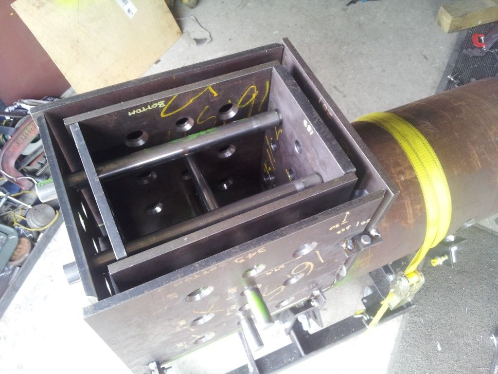
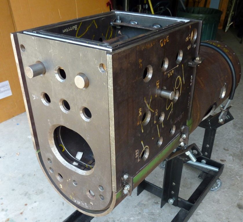
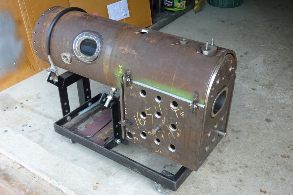
                            View of the assembled boiler on the support trolley.

                            2053 boiler assy 3 (medium).jpg

                            Boiler assembly rotated to the correct orientation with manhole reinforcing ring, steam ports and fire door ring in position.

                            2054 assy - rear (medium).jpg

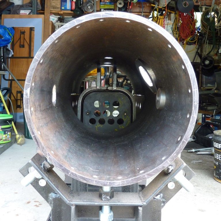
                            Boiler rear view (rear plate removed)

                            2055assy - front view (medium).jpg

                            Boiler front view (front tube plate removed)

                            Note: Two extra holes for tubes will be cut after the fire box is welded. The holes are too close to the edge and may distort at welding.

                            2060 assembly jigs (medium).jpg

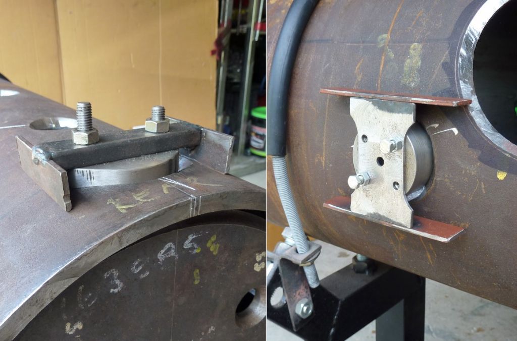
                            Details of the assembly jigs which were made for holding the water and steam ports in position while they are being welding in place.

                            2061 steam ports (medium).jpg

                            Sockets for the ports and fusible plug were made from round bar. These will be welded into the boiler shell. The BSP threads were not fully cut and will be finished after welding, in case there is ant distortion at welding.

                            2062 manhole bridge (medium).jpg

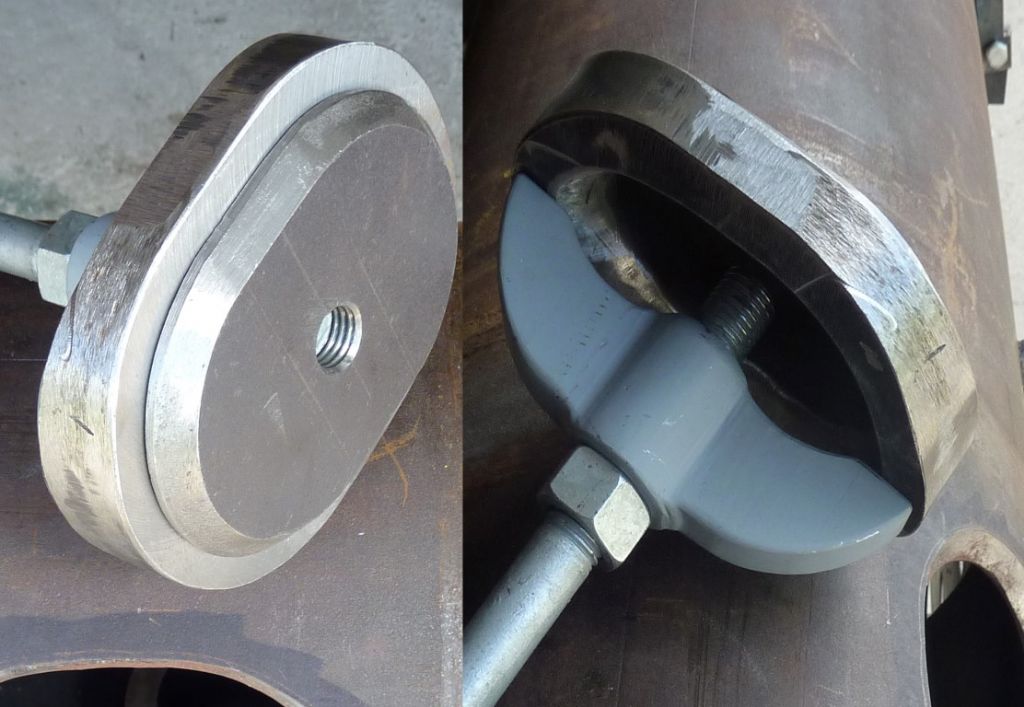
                            The Boiler Manhole Bridge was fabricated from a piece of round bar and two profiled plates for the wings. The wings were welded to the bar and cleaned up on my mill. The fillet radius was cut with bull nose cutter. A clearance hole for the manhole clamping bolt is being drilled.

                            #214367
                            Paul Lousick
                            Participant
                              @paullousick59116

                              In the words of that famous cartoon rabbit

                              thats all folks.jpg

                              This engine build has been a record of the main components of the Ruston and Proctor steam traction engine that I have been building for the past 3 years. I now have to manufacture some of the remaining parts but will add more posts when they are completed.


                              Thank you to all of the readers who have sent encouragement and positive comments about this post.

                              I have one more thing to add :

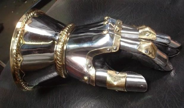
                              gauntlet.jpg

                              A challenge to other readers to add a bigger model build post.

                              Paul.

                              Edited By Paul Lousick on 28/11/2015 09:25:40

                              #223449
                              Paul Lousick
                              Participant
                                @paullousick59116

                                WELDING OF BOILER

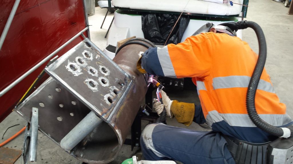
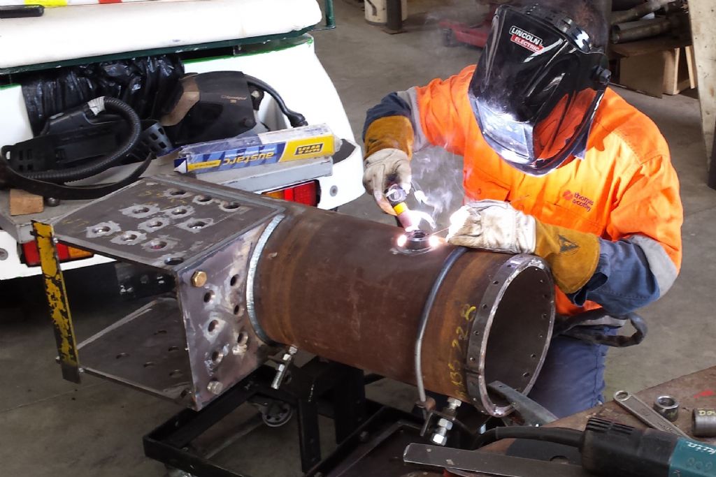
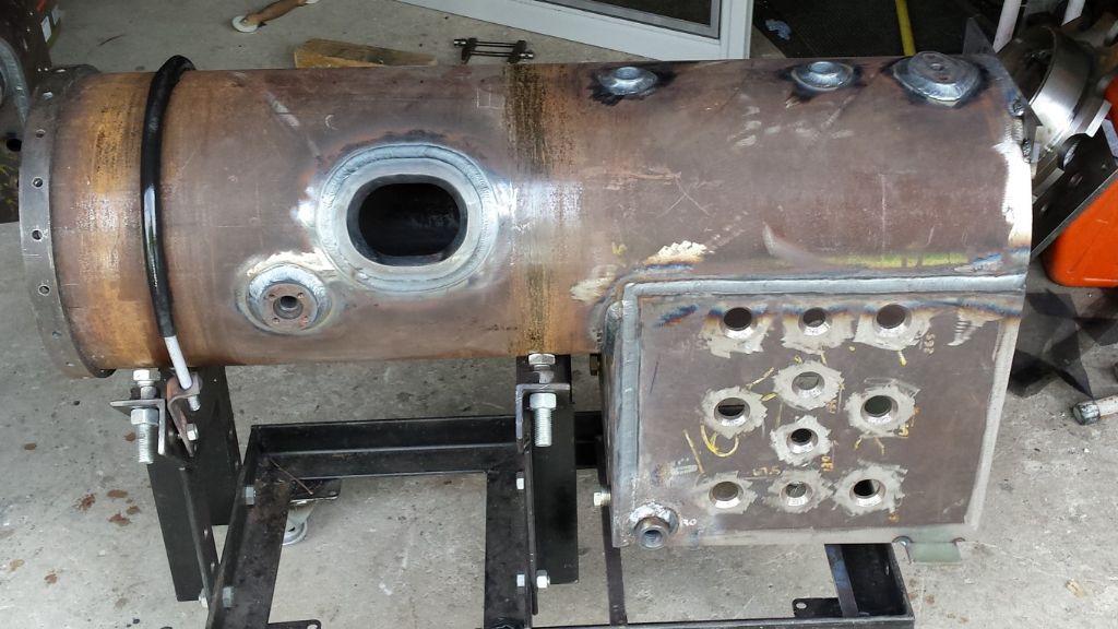
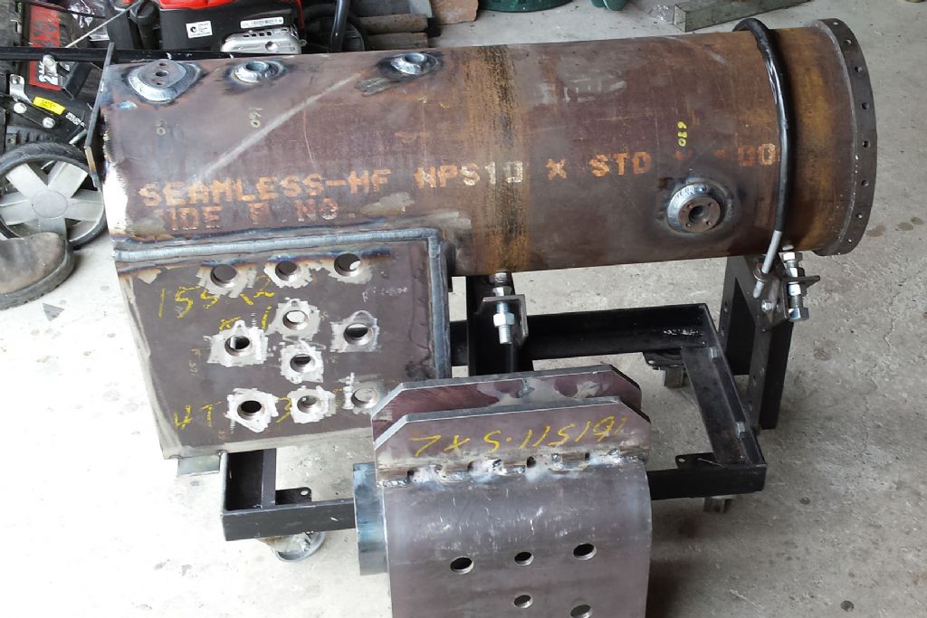
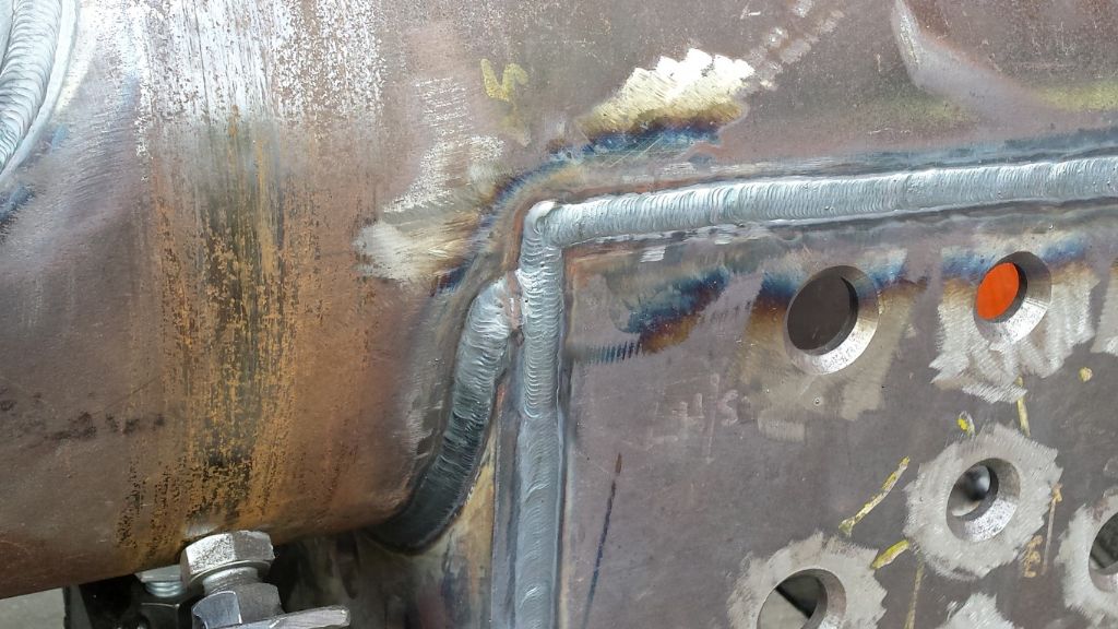
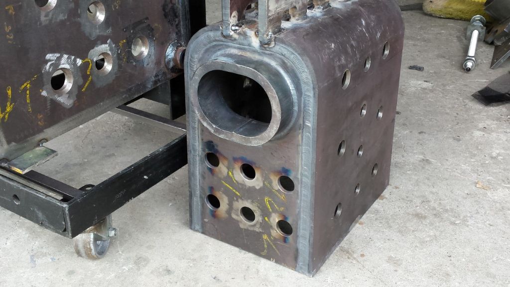
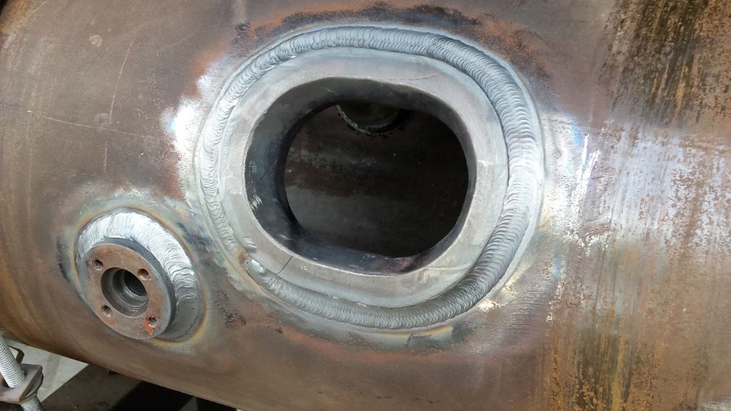
                                The majority of the welding of the outer shell of the boiler and the fire box was carried out with a TIG welder. A stick welder was use on a couple of places where there was limited access for the TIG. The welding process took much longer than expected but the finished welds were excellent.

                                welding boiler 01 (medium).jpg welding boiler 02.jpg

                                welding boiler 04 (medium).jpg welding boiler 03.jpg

                                welding boiler 05 (medium).jpg welding boiler 06 (medium).jpg

                                welding boiler 07 (medium).jpg welding boiler 08 (medium).jpg

                                #223470
                                Anonymous

                                  Good grief, that's pretty darn neat welding. Must be one hell of a TIG welder to cope with thick steel plate? What size electrode and were the welds done in one pass?

                                  Andrew

                                  #223474
                                  Paul Lousick
                                  Participant
                                    @paullousick59116

                                    Welding done by a top class welder who normally works on high pressure piping with years of practice. Used 2mm rods and multiple passes to build up the weld using a $6000 welding machine. Most of the welds were done from one side only and required a big joint preparation to achieve full penetration. Took about 15 hours to complete the job and consumed an E-size bottle of Argon gas. And boiler not finished yet.


                                    Edited By Paul Lousick on 01/02/2016 12:09:26

                                    #223483
                                    Harry Wilkes
                                    Participant
                                      @harrywilkes58467

                                      Great collection of interesting photos it's going to be one very nice engine when finished smiley

                                      H

                                      #223484
                                      Nick_G
                                      Participant
                                        @nick_g

                                        .

                                        This is brilliant. yes

                                        Your dedication to a long term project and obvious skill is to be admired. smiley

                                        Nick

                                        #223515
                                        KWIL
                                        Participant
                                          @kwil

                                          The last pass of welding is superb, don't you know the penetration and build up layers are equally brilliant! yesyes

                                          #314174
                                          Phillip Smith 4
                                          Participant
                                            @phillipsmith4

                                            Hello Paul,

                                            In your earlier posts on the machining of the cylinder casting, you mentioned that the ports connect to passages. How are the steam passages arranged within the cylinder?

                                            Thanks.

                                            Phill.

                                            #396501
                                            Paul Lousick
                                            Participant
                                              @paullousick59116

                                              Building my Ruston proctor SD traction engine has been massive project and I am nearing the end after 6 years. I have posted updates on the Traction Talk web site, also a lot work. This is a link to the site for anyone interested.

                                              Paul

                                              **LINK**

                                              EDIT. You will need to be a member to see the posts and it can be a long drawn out process to get approved.

                                              Edited By JasonB on 16/02/2019 09:14:10

                                              #396644
                                              Paul Lousick
                                              Participant
                                                @paullousick59116

                                                Thanks Jason,

                                                TT is a good site for those interested in traction engines. Mainly full size but also for models. I thought that visitors could view posts and only members could post. So will copy files to MEW.

                                                Paul

                                                #396652
                                                Paul Lousick
                                                Participant
                                                  @paullousick59116

                                                  6" Ruston Proctor SD – Hornplates

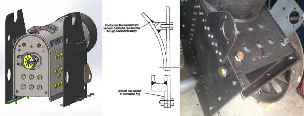
                                                  The Australian code for model steel boilers shows the hornplates attached to support brackets on the side of the boiler and not to threaded holes in the boiler side stays. Loading bolts in shear is not good design practice and not recommended.   I also added a plate at the bottom of the hornplate which the boiler sits on, eliminating the shear force on the bolts. Having a gap between the hornplates and the firebox with no direct contact will also help to insulate the boiler.

                                                  2001.jpg


                                                  Both hornplates were plasma cut and tacked together to enable all holes to be drilled at the same time using the milling machine’s digital readout to accurately position all holes.

                                                  The large hole for the crankshaft bearing rough cut with a series of large holes using a rotor broach in the mill, then finished to size with a boring bar.

                                                  2002 milling hornplates.jpg


                                                  The mounting plate for the steering chain shaft was attached to the hornplate with ¼” round head steel rivets. The rear of the hornplates were countersunk and the rivets cold pressed requiring a force of 7 tonnes. The false rivets (just for show) were cut to slightly longer than the plate thickness and hammered flat with a ball peen hammer. They are non-load bearing and only need to be kept in place.

                                                  2003 pressing hornplates.jpg


                                                  Edited By Paul Lousick on 16/02/2019 22:32:02

                                                  #396653
                                                  Paul Lousick
                                                  Participant
                                                    @paullousick59116

                                                    Fabricating Saddle Plates

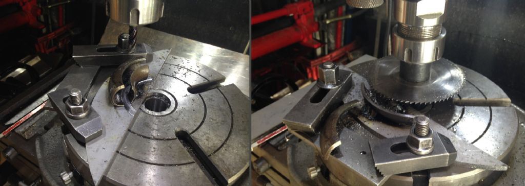
                                                    I wanted to make the saddle plates (aka spectacle plates) with rounded corners but did not have bending or forging equipment in my workshop. To do this I fabricated them using pipe elbows for the curved corners. The elbows were tack welded to a plate for mounting on the rotary table and milled as shown, then cut in half with a saw blade on the mill.

                                                    2005 rear spectacle plate.jpg

                                                    2006 spectacle plate corner.jpg

                                                    The plates were modelled in 3D, using the same radius as that on the pipe elbow and drawings were produced, using the sheetmetal features in Solidworks to produce a flat pattern for cutting the plate.

                                                    The edges of the plate bent and the elbow pieces welded in place. (Obtaining an exact distance between two flanges that are produced by bending is difficult but the the bend line position calculated in sheetmetal produced a good fit for the saddle plate between the two hornplates).

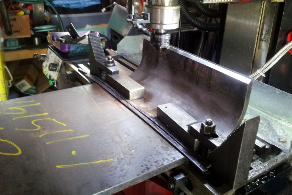
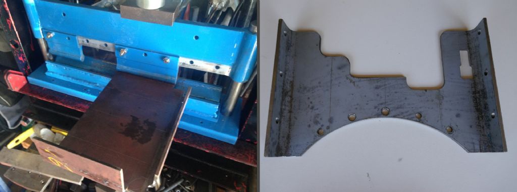
                                                    Bending the specific radius on the plates created another problem. As stated earlier, I did not have any bending equipment, so had to design and built a press brake for my 20t hydraulic press.

                                                    Bending rear saddle plate (left), Finished front saddle plate (right)

                                                    2007 bent plates.jpg

                                                    #396672
                                                    Paul Lousick
                                                    Participant
                                                      @paullousick59116

                                                      Machining Crankshaft

                                                      The crankshaft was purchase as a casting. The first operation was to clean up the crank area with a little fettling using a hand linisher and elbow grease.

                                                      2101 crankshaft & pulley assy.jpg

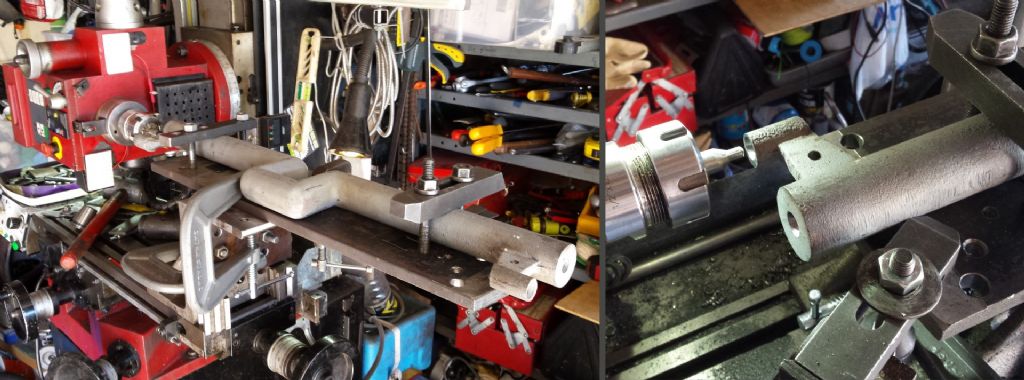
                                                      The crankshaft was mounted on a piece of steel flat bar for drilling centres in the ends of the crankshaft allowing it to be rotated by 180 degrees and keep the same plane thru the centres at both ends.

                                                      To drill the holes, the mill head was turned to operate horizontally and an edge finder used to find the centre of the crankshaft. After drilling the first hole the mill table was moved by a distance equal to the throw of the crank to drill the second hole.

                                                      2102 drill centres.jpg

                                                      Balance weights and jacking screws to prevent shaft bending were attached to the crankshaft while turning the crank journal and the lathe cutter had to be lengthened to clear the crank.

                                                      A steel block was wedged between the crank gap to resist any bending by the lathe centres and a steady rest used to stop vibration while turning the crank ends.

                                                      2103 turning crankshaft.jpg

                                                    Viewing 25 posts - 26 through 50 (of 63 total)
                                                    • Please log in to reply to this topic. Registering is free and easy using the links on the menu at the top of this page.

                                                    Advert

                                                    Latest Replies

                                                    Home Forums Traction engines Topics

                                                    Viewing 25 topics - 1 through 25 (of 25 total)
                                                    Viewing 25 topics - 1 through 25 (of 25 total)

                                                    View full reply list.

                                                    Advert

                                                    Newsletter Sign-up