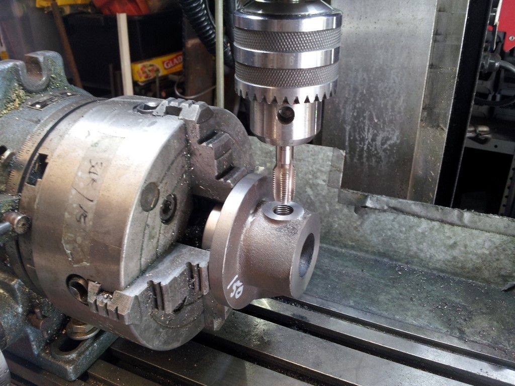
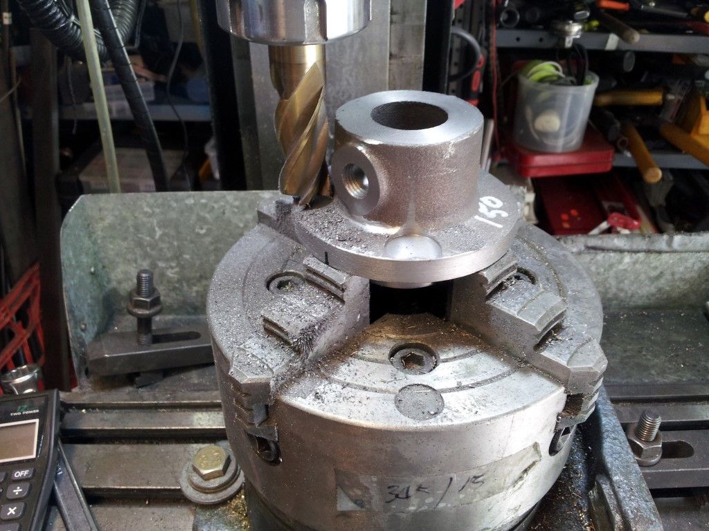
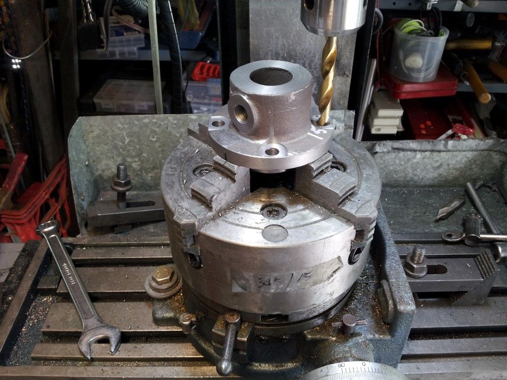
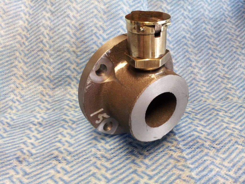
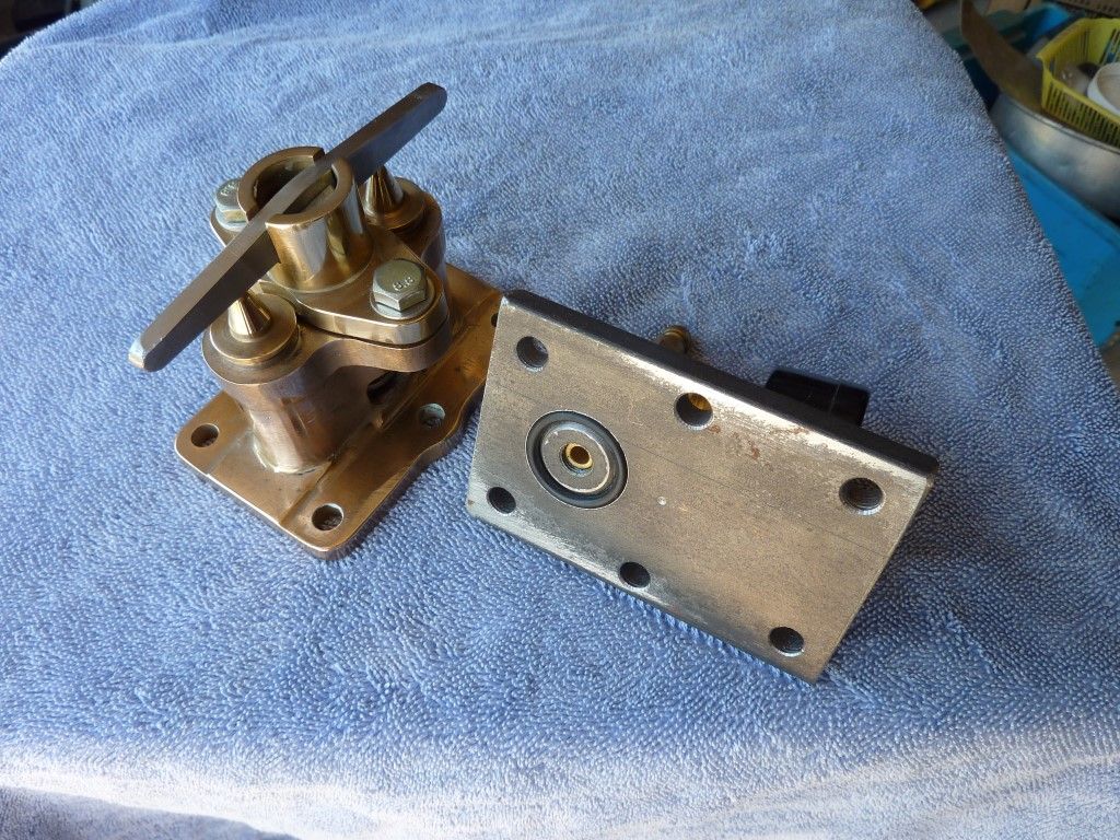
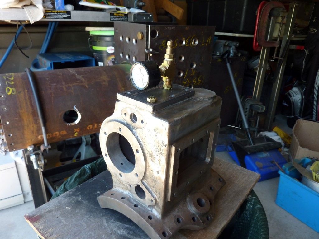
As I supported the request for more build threads thru a previous post, I am adding the build of my 6" Ruston Proctor Steam Traction Engine.
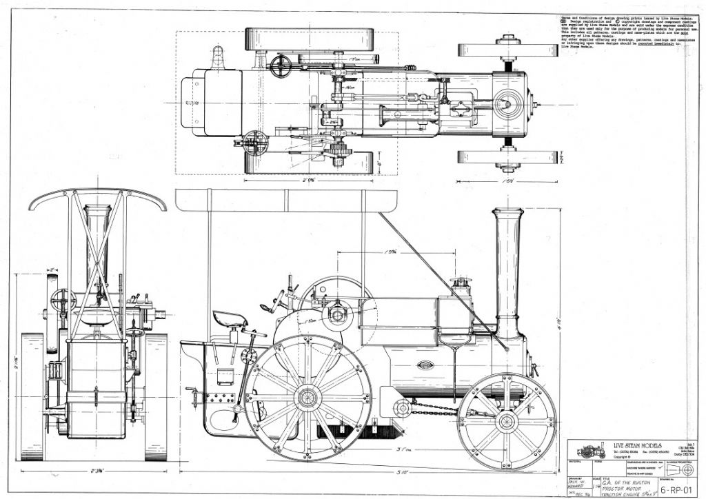
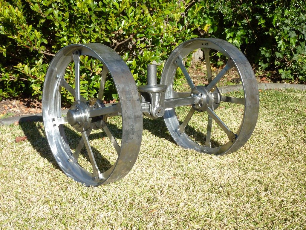
Even though the model is a half size scale model of the original, it is only a medium size engine. The original engine weighed 3 1/2 tons and the model will weigh about 650 kg. It has a 10" dia boiler and the rear wheels are 24" diameter. Small enough to transport is a standard 6' x 4' box trailer.

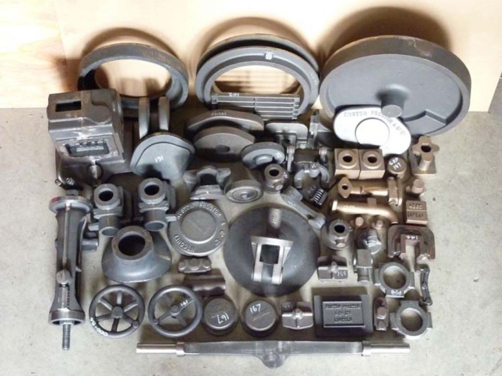
A set of drawings and castings was obtained from Live Steam Models and shipped by sea freight to Sydney, Australia.

The drawings for the model engine were drawn with imperial dimensions and specified inch size plates and pipe, many of which were not available. The biggest change that I had to make was making the boiler. The drawing specified a barrel of 10" OD (254mm) but this size is not available in commercial pipe, unless you rolled a special tube. I decided to use10" NB pressure pipe (273mm OD) but this meant changing the width of the engine. The distance over the horn plate was now wider which effected the width of the rear axle and most of the components.
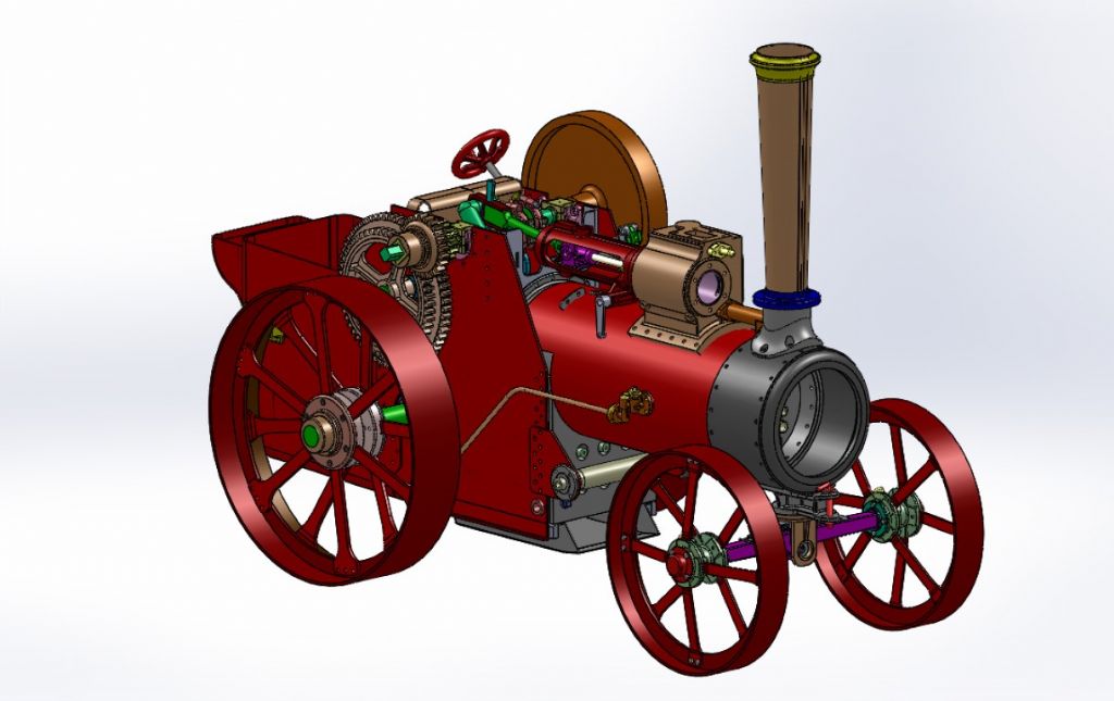
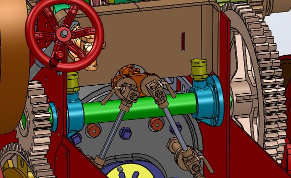
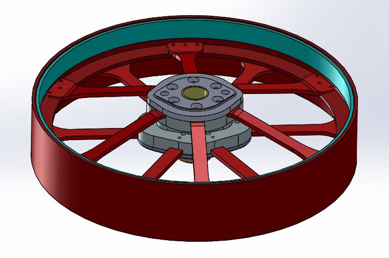
Because of all these changes and some mistakes and missing dimensions, I re-drew all parts of the engine using Solidworks CAD software and created my own set of detail drawings.

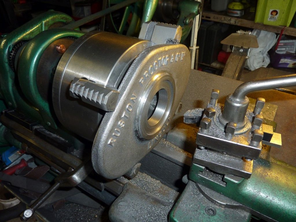
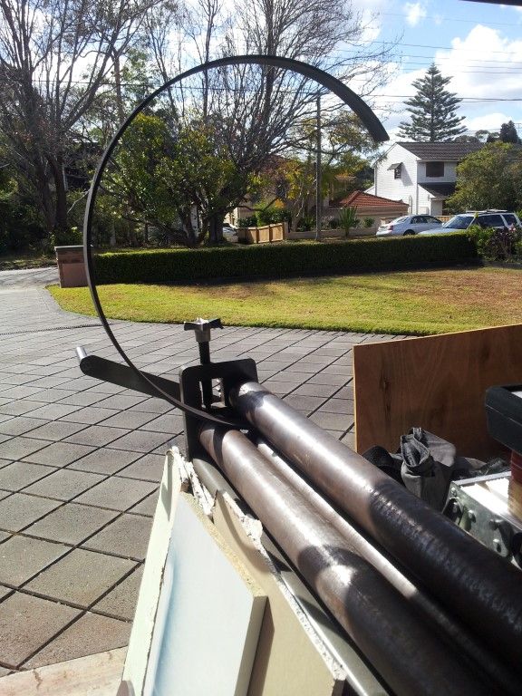
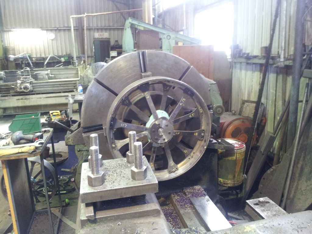
I had worked for most of my working life as a mechanical engineering draftsman but have had little experience actually running a mill and a lathe and was advised by a toolmaker to start with the front wheels as they were a good introduction to the different machining techniques.

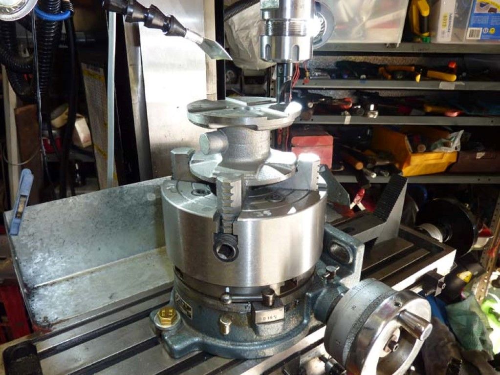
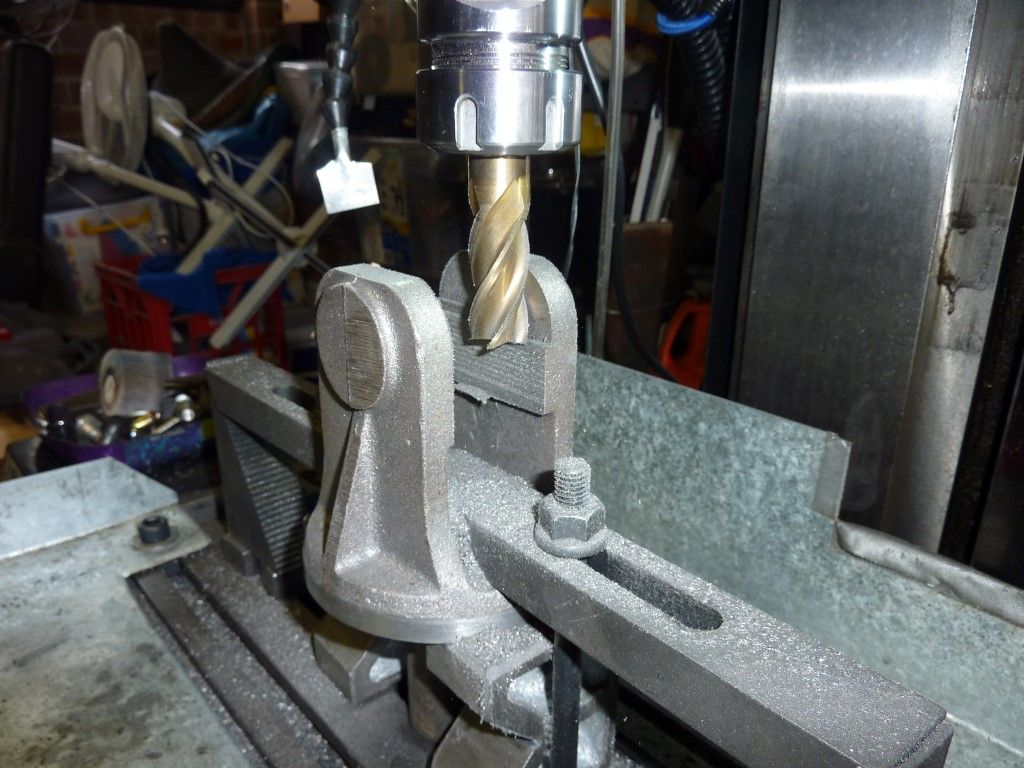
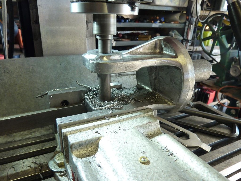
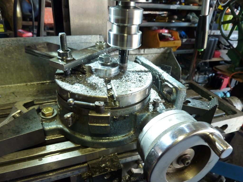
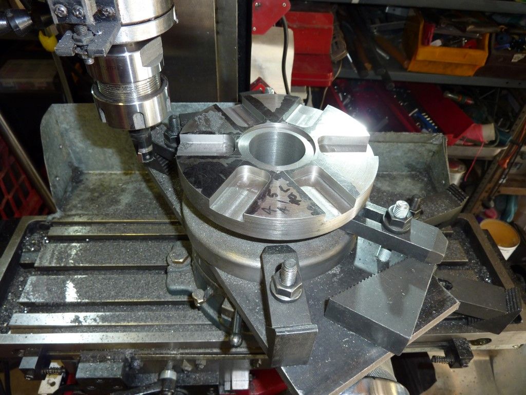
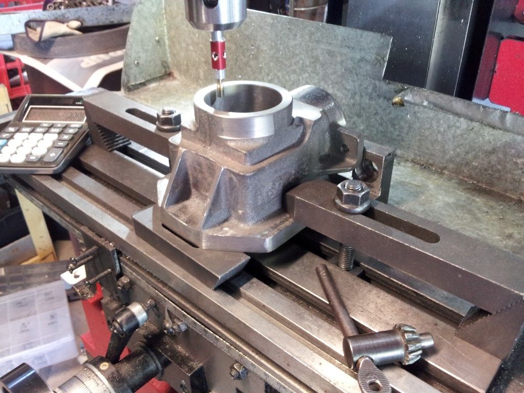
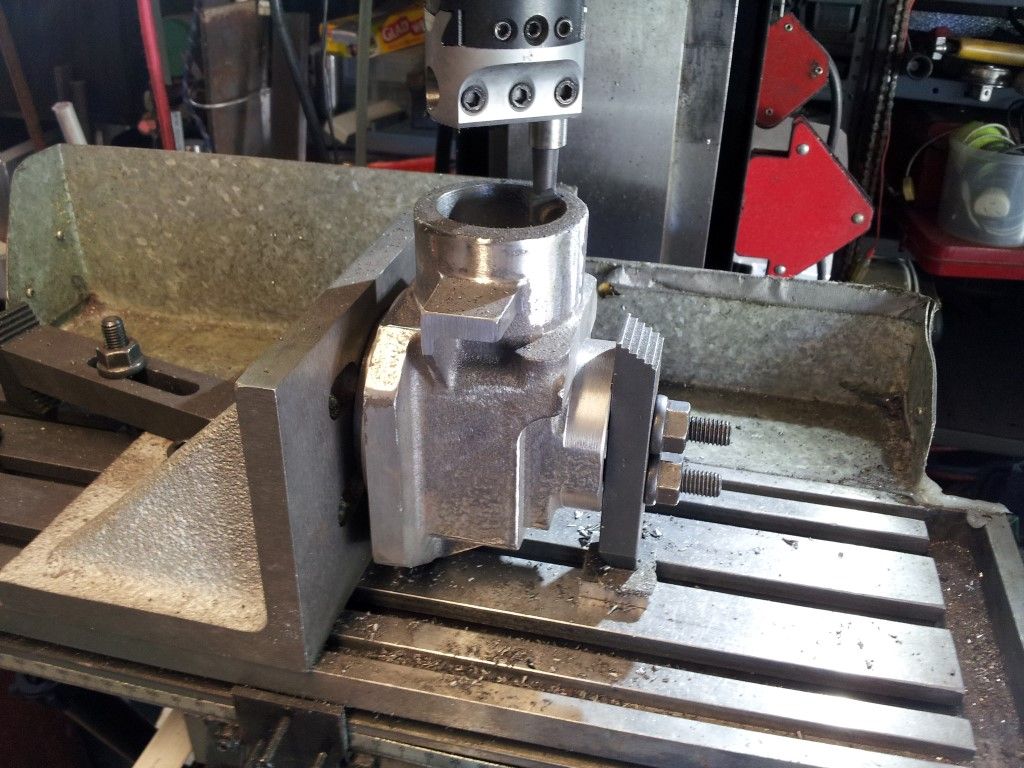
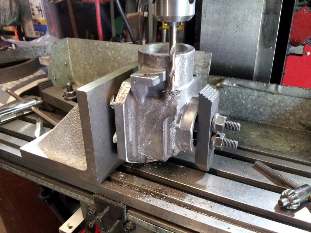
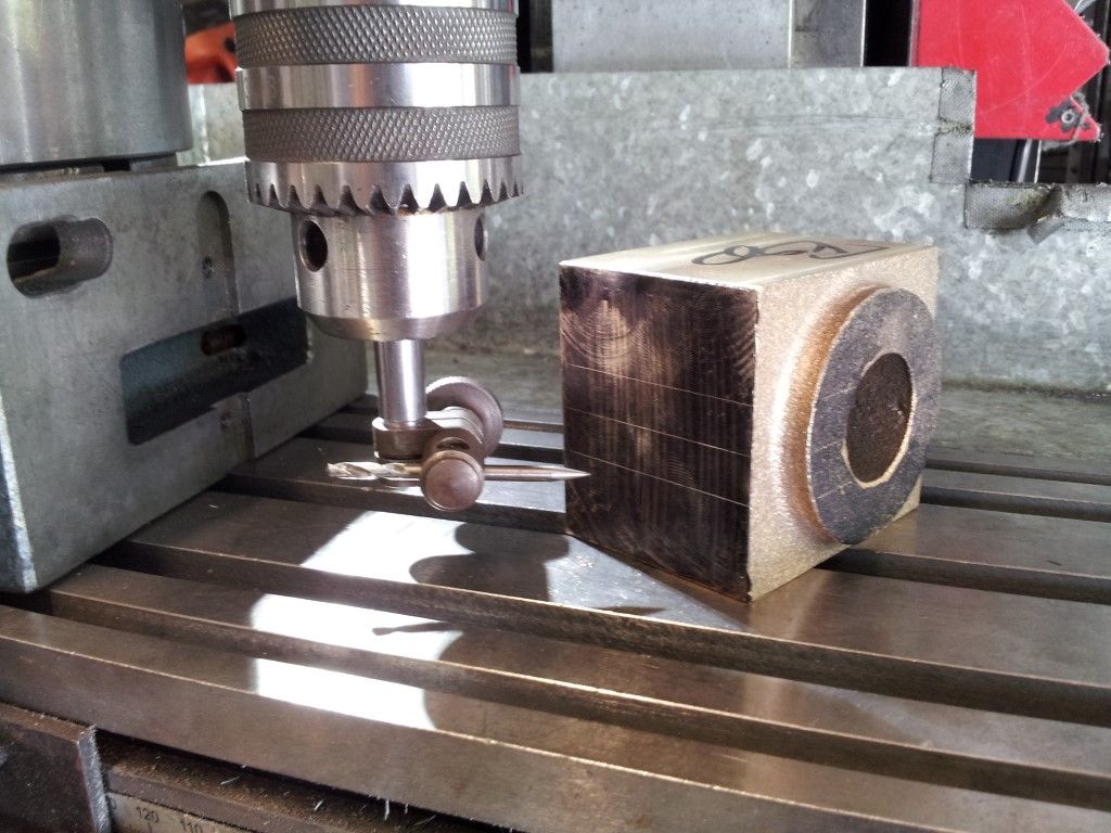
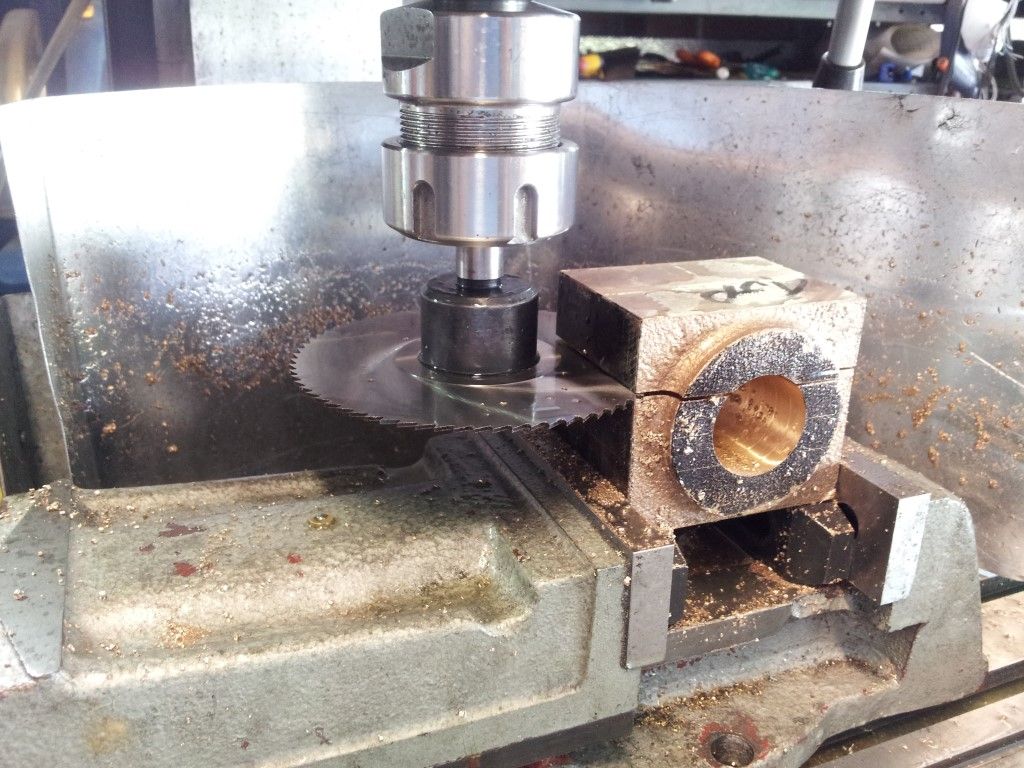
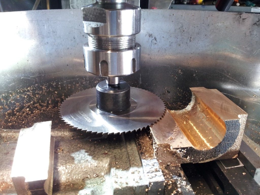
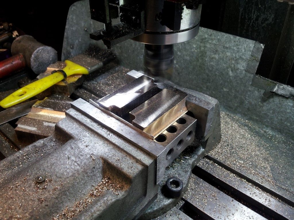
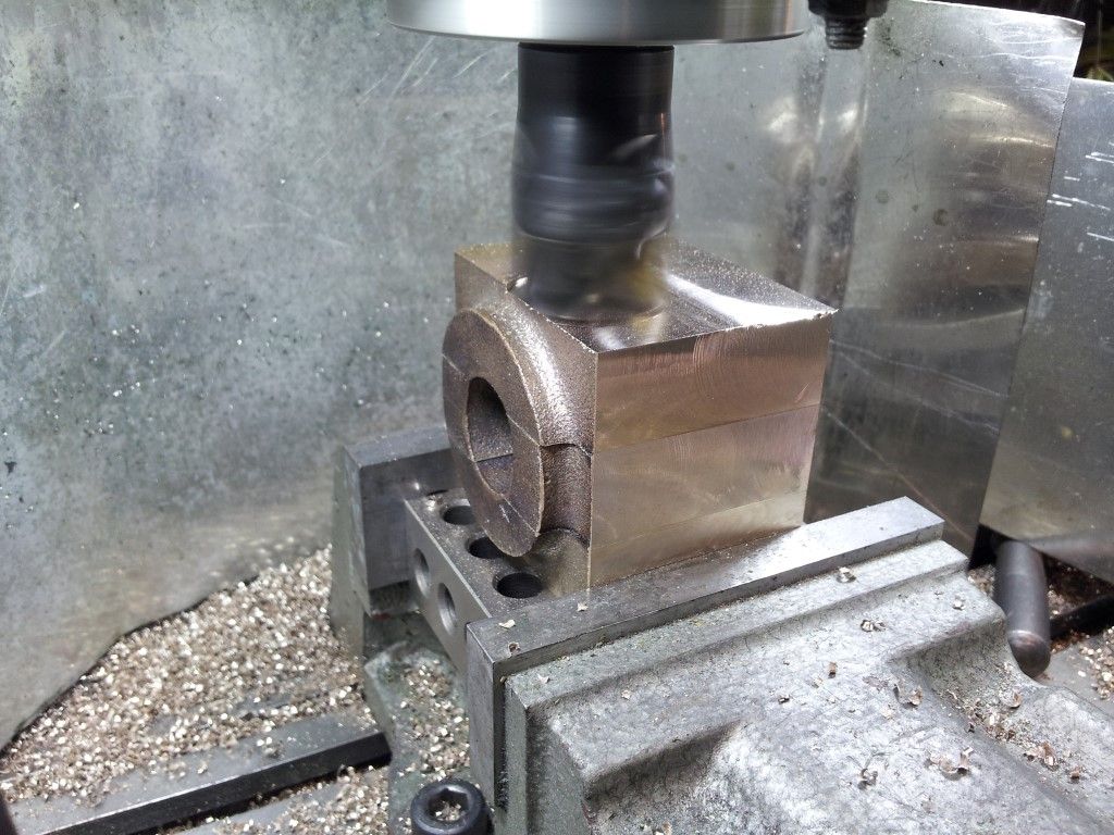
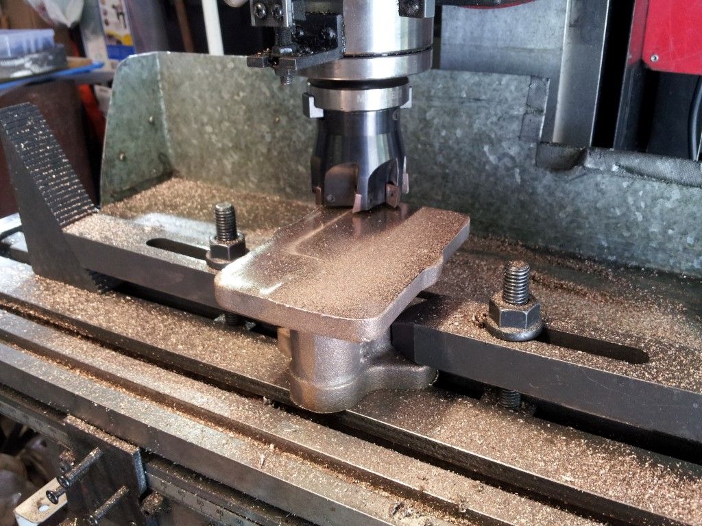
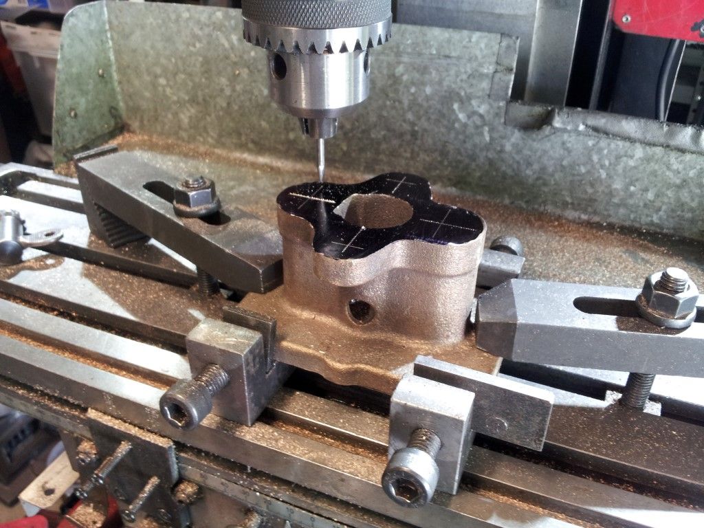
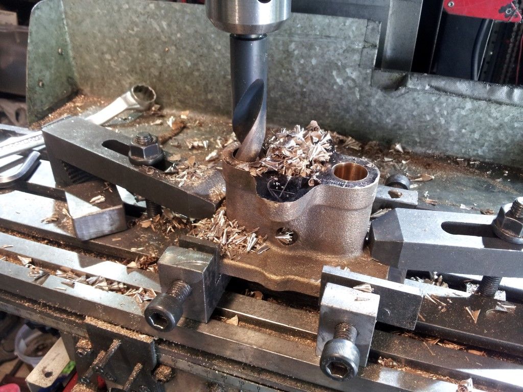
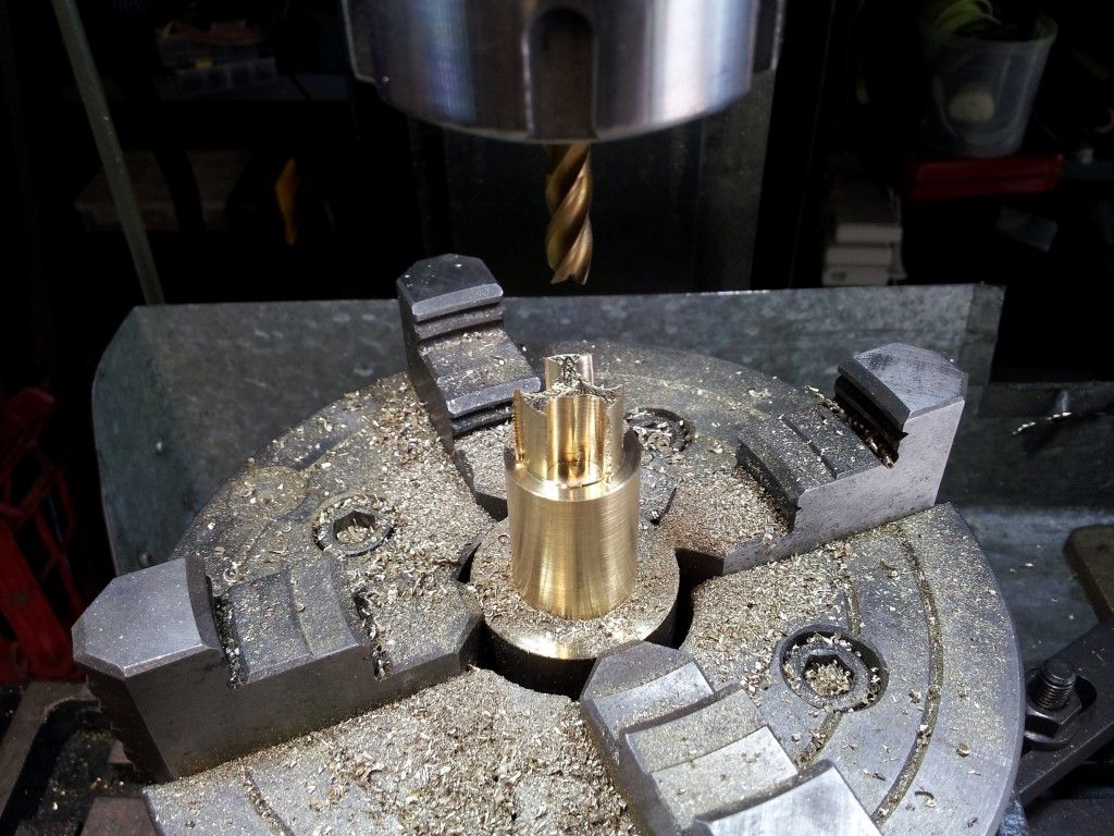
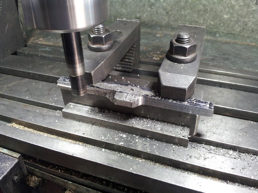
Milling the slots in the front wheel hubs for the spokes.
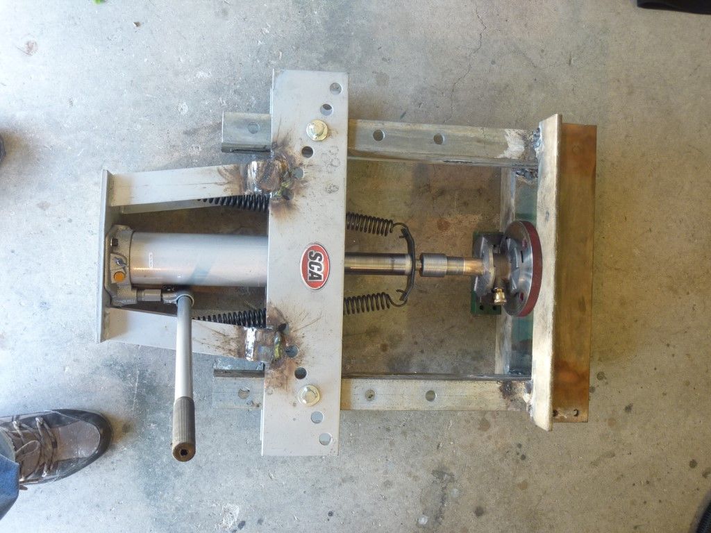
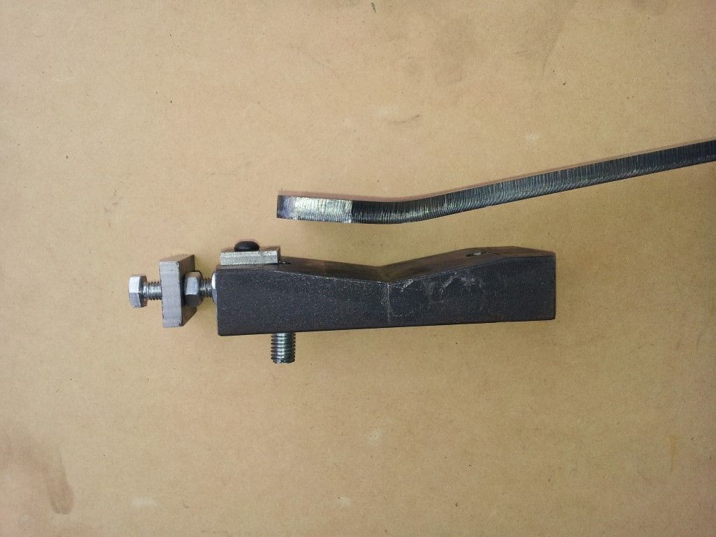
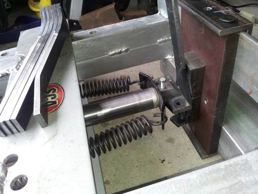
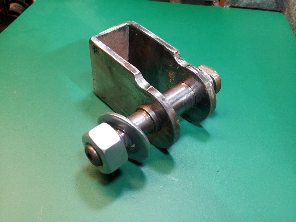
To bend the wheel spokes, I used a press which I converted from a 12 tonne pipe bender and machined an angled plate to press against.

Home Made 12 Tone Press

The angle base plate for pressing bend in spokes required a little trial and error to achieve the correct angle to overcome the spring-back in the spoke angle when the press was released. This arrangement produced a consistent bend angle in all of the spokes.


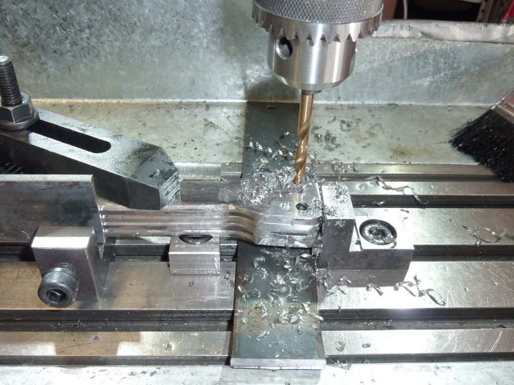
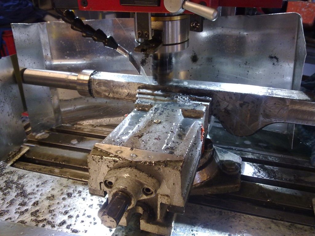
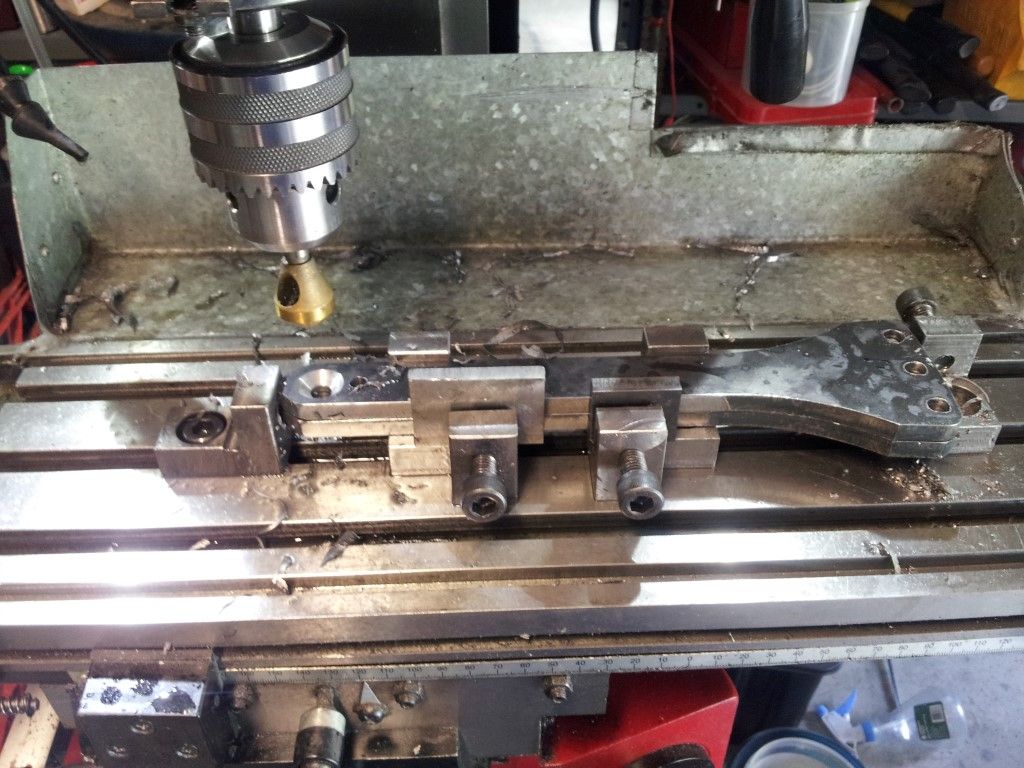
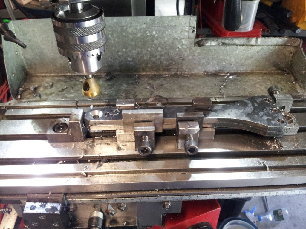
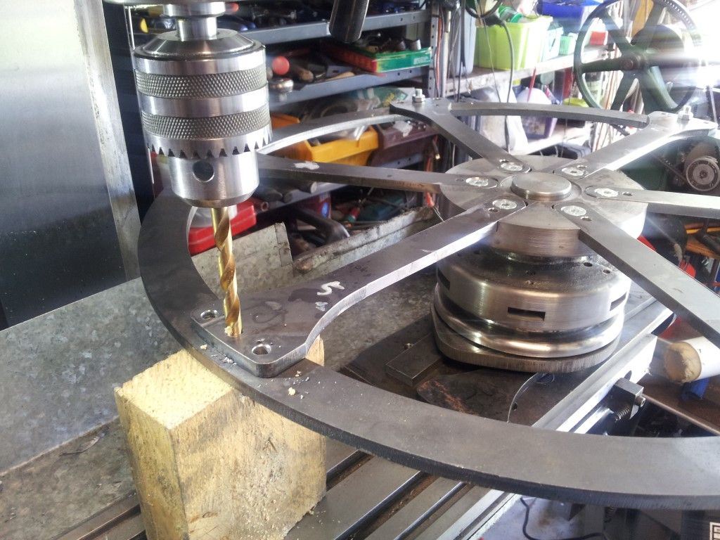
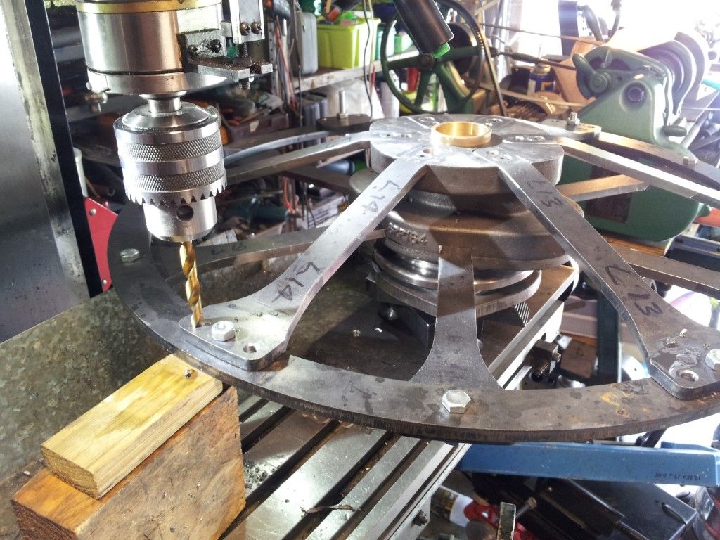
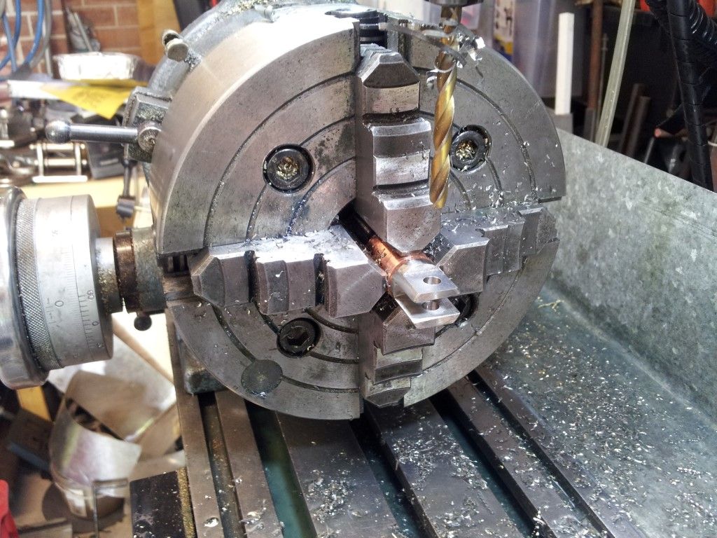
The holes in the spokes being stack drilled for the rivets which attach them to the wheel rim.

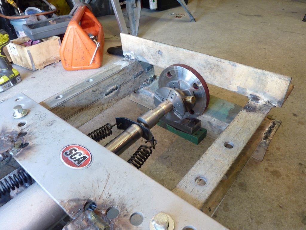
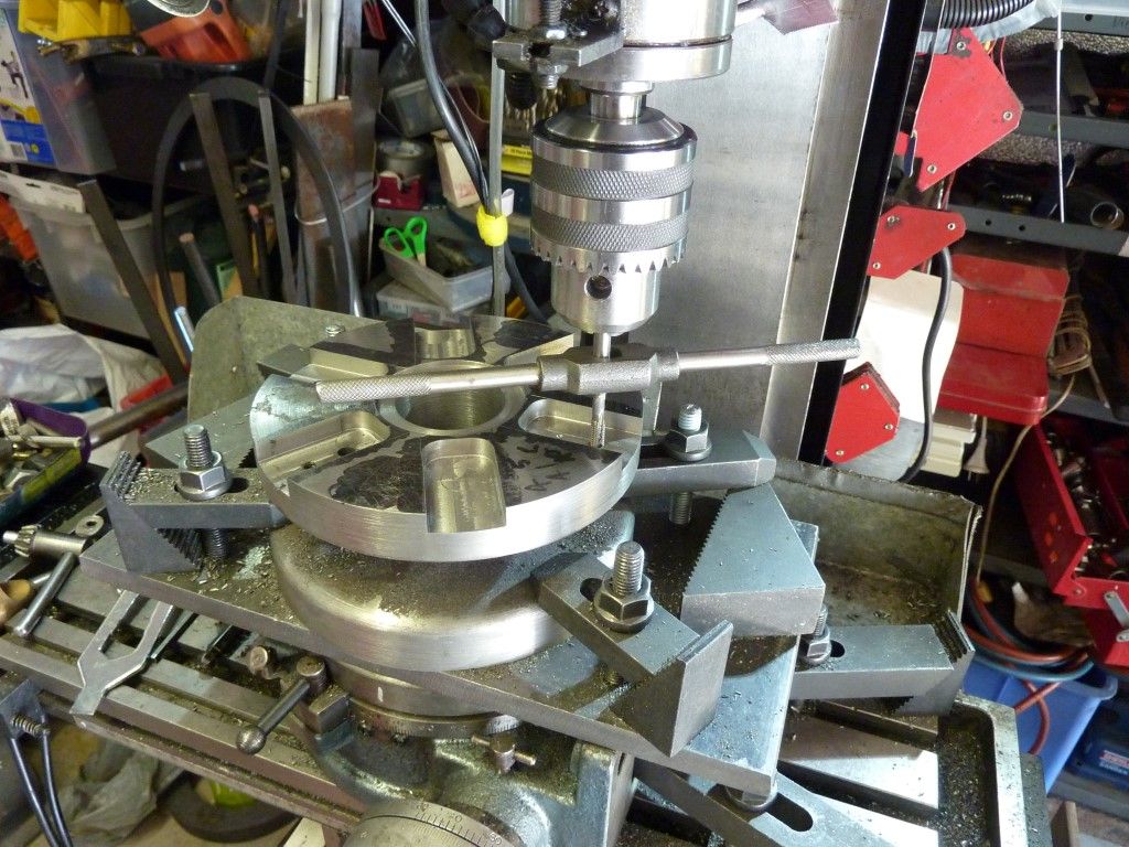
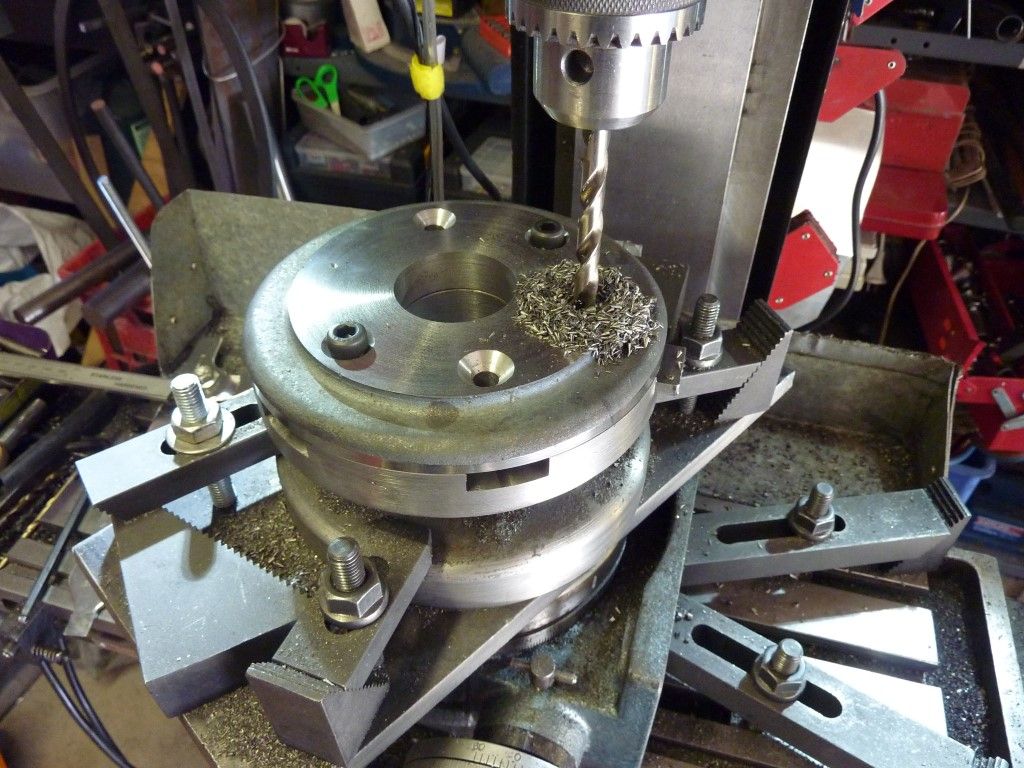
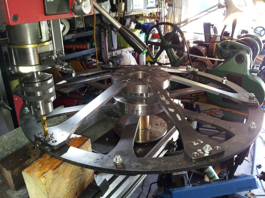
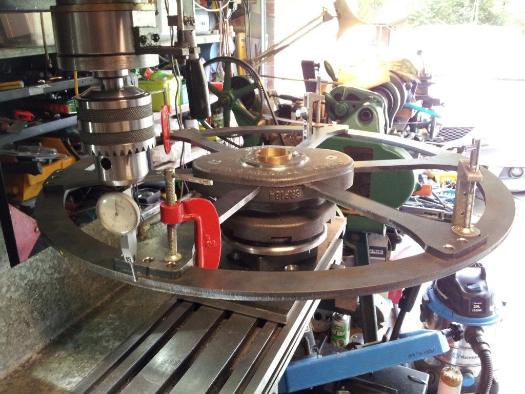
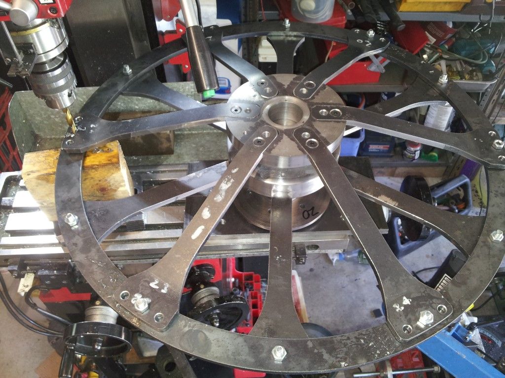
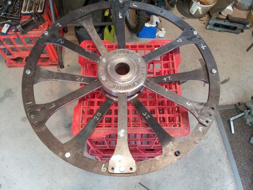
Wheel assembly mounted on a temporary axle which is bolted to the mill table. All spokes assembled in the wheel hub and the wheel ring centered about the axle and mounting holes drilled.

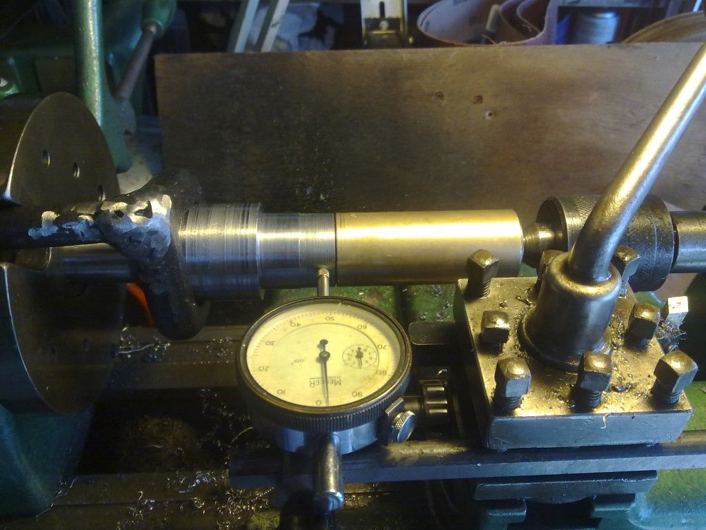
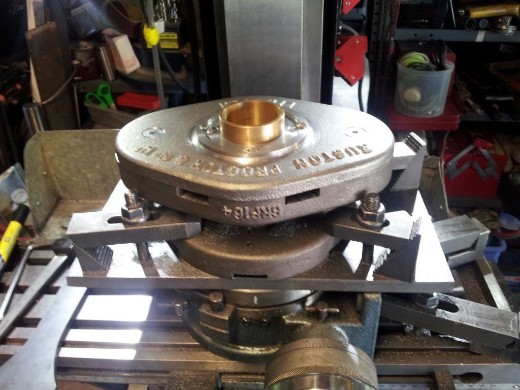
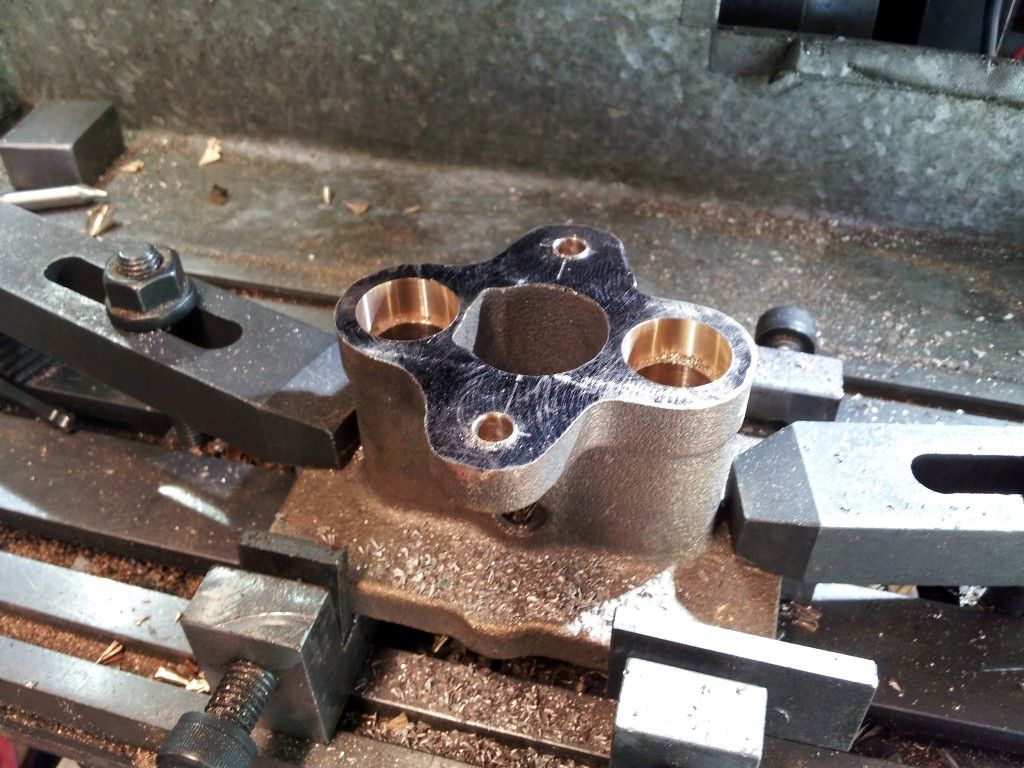
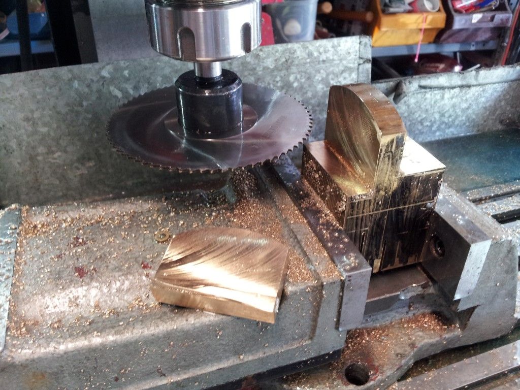
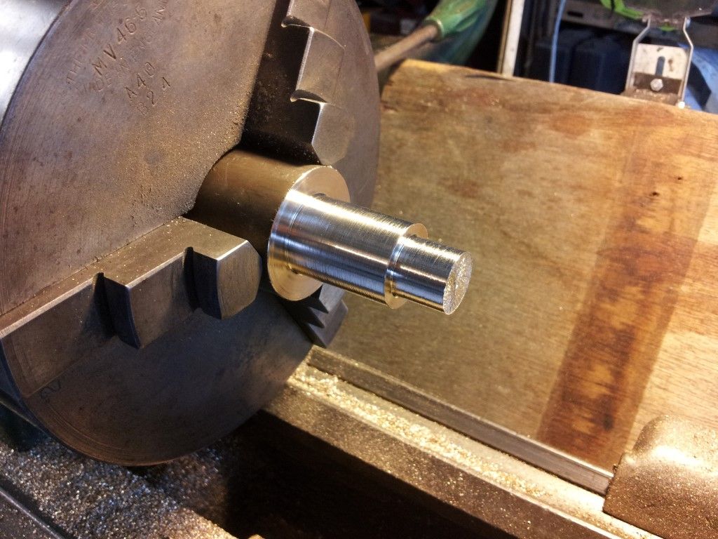
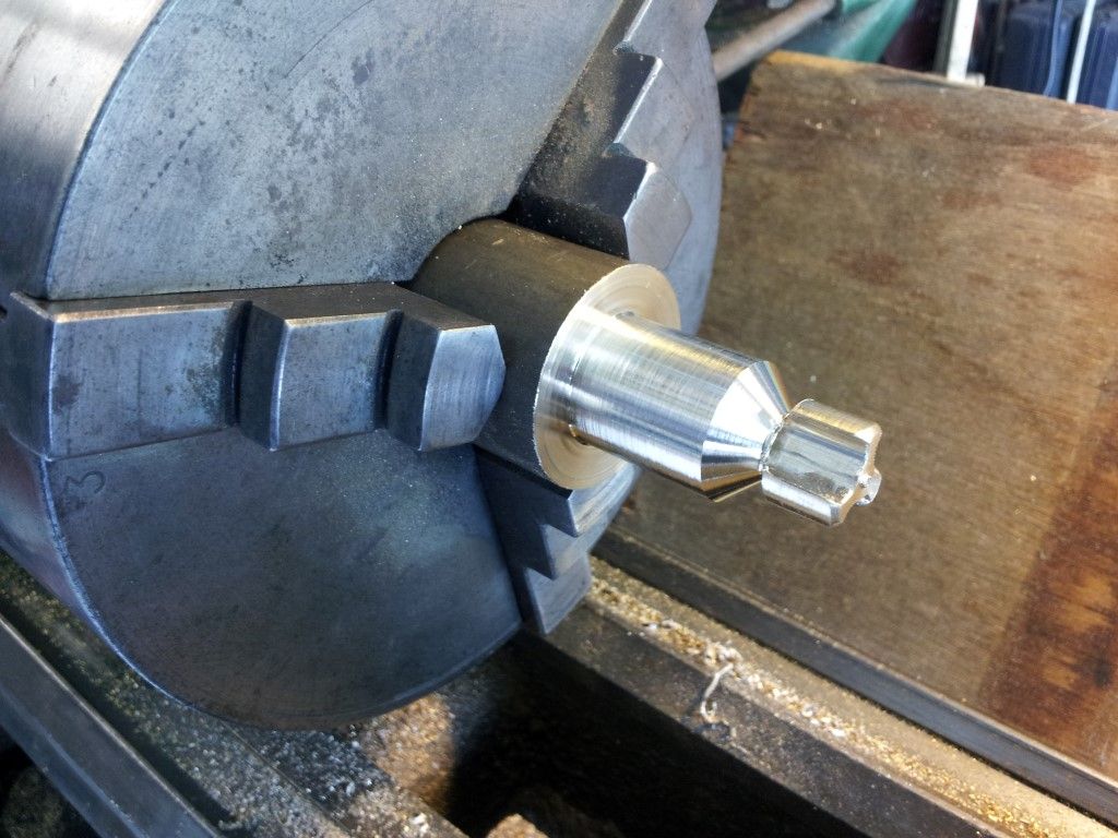
I did not have an accurate way to measure the bore for the wheel hub, only an outside micrometer, so made a Go/NoGo plug gauge. Then used the plug gauge to transfer the diameter to the bush. With the dial indicator I could machine the bush slightly bigger for a press fit.
The plug gauge became a universal tool for measuring and was also used as the axle which I used to assemble and drill the spokes on the mill. (shown in previous photo).

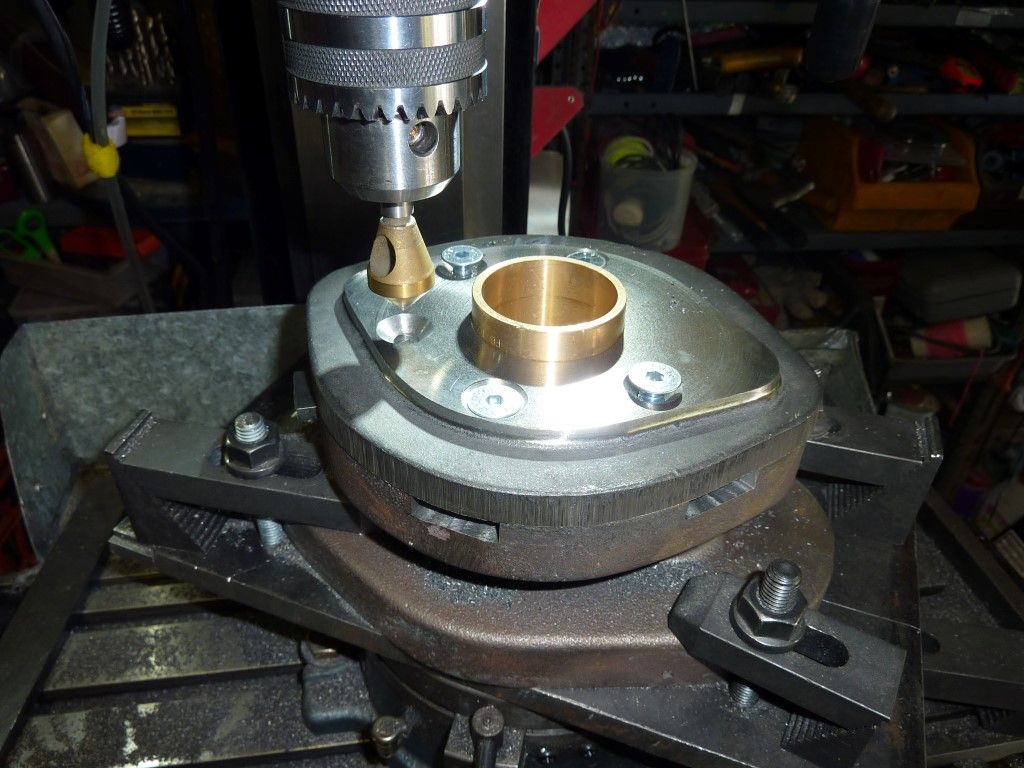
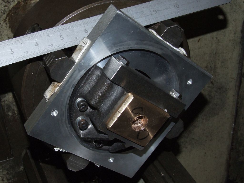
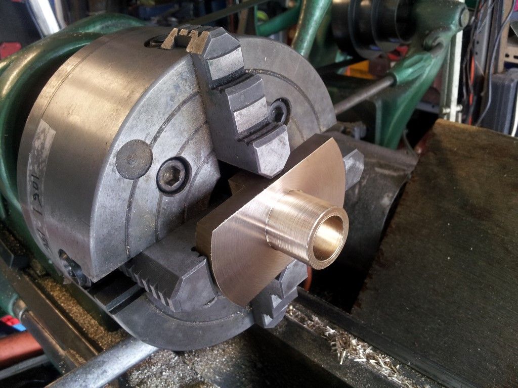
Pressing bronze bush into wheel hub
 Jon Cameron.

