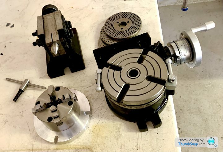
5” Rotary Table/Tailstock/Chuck Kit Info/Questions
5” Rotary Table/Tailstock/Chuck Kit Info/Questions
- This topic has 24 replies, 11 voices, and was last updated 1 October 2021 at 15:52 by
 Kevin D.


- Please log in to reply to this topic. Registering is free and easy using the links on the menu at the top of this page.
Latest Replies
-
- Topic
- Voices
- Last Post
-
-
Motor Boys
Started by:
bernard towers
in: General Questions
- 1
-
23 February 2025 at 00:17
bernard towers
-
3/16” BSF mill gib screws
Started by:
Graham Horne 2
in: General Questions
- 9
-
22 February 2025 at 23:50
Nigel Graham 2
-
Electric Mobility
Started by:
Vic
in: The Tea Room
- 3
-
22 February 2025 at 22:48
Michael Gilligan
-
Arceurotrade New Sieg SC4 Lathe.
Started by:
Lathejack
in: Manual machine tools
- 2
-
22 February 2025 at 22:39
Andrew Tinsley
-
Centec 2b mill rebuild
Started by:
Graham Horne 2
in: Manual machine tools
- 3
-
22 February 2025 at 22:13
Graham Horne 2
-
Martin Evans Metro
Started by:
Philip Wheatcroft
in: Locomotives
- 2
-
22 February 2025 at 20:54
Alan Donovan
-
Homemade Headstock Lathe 1 fondry work
Started by:
celso ari schlichting
in: General Questions
- 4
-
22 February 2025 at 20:36
celso ari schlichting
-
Recommended books for starting model engineering
Started by:
Andrew Schofield
in: Beginners questions
- 2
-
22 February 2025 at 19:23
bernard towers
-
New Myford ML4 Owner in Need of parts
Started by:
castingflame
in: Introduce Yourself – New members start here!
- 5
-
22 February 2025 at 18:58
Robert Atkinson 2
-
Vickers Inverted Engine
1
2
Started by:
JasonB
in: Stationary engines
- 10
-
22 February 2025 at 18:55
JasonB
-
My week this week! My workshop videos
1
2
…
11
12
Started by:
Phil Whitley
in: The Tea Room
- 13
-
22 February 2025 at 17:56
Phil Whitley
-
VERY delicate rust removal
Started by:
beeza650
in: Beginners questions
- 14
-
22 February 2025 at 15:11
SillyOldDuffer
-
How do I resin cast tiny seats for my Airliner model?
Started by:
Simon Robinson 4
in: Beginners questions
- 3
-
22 February 2025 at 15:00
JasonB
-
Lampertheim Model Engine Show 2025
Started by:
JasonB
in: Exhibitions, Shows and Club Events
- 2
-
22 February 2025 at 14:27
Graham Titman
-
NEW LOOK – Model Engineer & Workshop
1
2
…
6
7
Started by:
sohara
in: Model Engineer & Workshop
- 53
-
22 February 2025 at 14:20
Grahame Chambers 1
-
indexing head lathe
1
2
Started by:
Danni Burns
in: Manual machine tools
- 16
-
22 February 2025 at 14:15
Hugh Stewart-Smith 1
-
Diamond Wheel dressing attachment
Started by:
David George 1
in: Help and Assistance! (Offered or Wanted)
- 10
-
22 February 2025 at 13:13
David George 1
-
Wooden item – what is it
Started by:
Bazyle
in: The Tea Room
- 5
-
22 February 2025 at 12:04
SillyOldDuffer
-
Myford ML10
Started by:
notyet
in: Workshop Tools and Tooling
- 5
-
22 February 2025 at 11:25
Howard Lewis
-
Lathe Chuck thread size
Started by:
Bootlegger Blacky
in: Workshop Tools and Tooling
- 5
-
22 February 2025 at 11:22
Howard Lewis
-
Just purchased a lot of stuff
Started by:
beeza650
in: Beginners questions
- 6
-
22 February 2025 at 11:16
Howard Lewis
-
P M s
Started by:
Howard Lewis
in: Website Questions, Comments, and Suggestions
- 2
-
22 February 2025 at 10:25
Howard Lewis
-
Cannot access homeworkshop.
Started by:
Graham Titman
in: The Tea Room
- 8
-
22 February 2025 at 10:04
Emgee
-
End mill sharpening fixture
Started by:
celso ari schlichting
in: General Questions
- 4
-
22 February 2025 at 09:52
Michael Gilligan
-
Lathe help information
Started by:
maccecht
in: Help and Assistance! (Offered or Wanted)
- 13
-
21 February 2025 at 22:53
Howard Lewis
-
Motor Boys