5 inch 0-4-0 Shunter

Advert

5 inch 0-4-0 Shunter

Home Forums Locomotives 5 inch 0-4-0 Shunter

Viewing 25 posts - 26 through 50 (of 135 total)
  • Author
    Posts
  • #354127
    Ron Laden
    Participant
      @ronladen17547

      You cant guarantee the output Roy, they are off the shelf can motors and unless you have a duff motor the two motors output should be within 3 or 4 percent of each other and they will be fine. The motors are driving the same spur gear and will balance out albeit one will be working a little harder. Obviously if you had motors with a difference of 10% or greater then that would become more of an issue.

      Ron

      Edited By Ron Laden on 15/05/2018 19:08:05

      Edited By Ron Laden on 15/05/2018 19:10:01

      Advert
      #354129
      Jon Lawes
      Participant
        @jonlawes51698

        An interesting little project.

        #354151
        duncan webster 1
        Participant
          @duncanwebster1
          Posted by roy entwistle on 15/05/2018 18:41:48:

          How are you going to guarantee the same output from two motors on one axle ?

          Just curious Roy smiley

          Does it matter, I don't think so, as long as it's something like it will be OK

          #354154
          Jeff Dayman
          Participant
            @jeffdayman43397

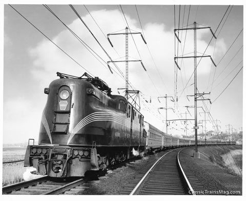
            I don't think it matters either. One of the most famous electric locomotives in the world, Pennsylvania Railroad's GG1 in the USA, used two 385 HP motors per wheel set / axle with a "quill" axle. Motor pinions drove quill gear, quill applied force to modified spokes of each wheel via spring cups on the quill. Only 4620 HP total though, and only lasted from 1930's to 1990's, but hey….. 2 motors each axle might just work for your 0-4-0 project. Pics from various websites below.

            quill-fig1.jpg

            prr_gg1_congressional.jpg

            Edited By Jeff Dayman on 16/05/2018 04:58:13

            #354168
            Ron Laden
            Participant
              @ronladen17547

              That was some loco Jeff, thanks for the pictures. I see from the picture of the motors that they were mounted on the axle as you can see the axle bearings below the motors. This is the way I am mounting my motors, the motor mounting plate has a central bearing which the axle runs through. With the axles having suspension (springs) it was the easiest way I could see to maintain the relationship/position between the motor pinion gears and the drive spur gear which is fixed to the back of the wheels.

              I am reasonably confident it should work ok but wouldnt want to count my chickens too soon.

              Since I started the design I have changed the gear ratio, due mainly to availability of suitably sized gears at the right price. The ratio is now 6.25 to 1 this should give approx 7 – 8 mph top speed. I have gone with MOD 1.0, I considered finer gears but I thought MOD 1.0 had a little more meat to them without them being too coarse.

              There is no clever calculations to any of this its mainly my gut feeling with a bit of "if it looks right it probably is"

              I,m getting itchy fingers as I want to get the build started but as I dont have any machining I have to rely on other people for machined parts. I can and will do a lot by hand but at the moment still waiting for chassis parts before I can make a start.

              Ron

              Edited By Ron Laden on 16/05/2018 09:43:04

              #354530
              Ron Laden
              Participant
                @ronladen17547

                Well whilst waiting for chassis parts to arrive I have started on designing the loco body. The main body panels will be from 6mm Birch plywood with some thin sheet aluminium and plastic etc.

                Obviously this will not be a scale loco but a sort of look alike, "very loosely" based on a 03/04 type shunter. The size of the body will be no where near scale, thats impossible as having to house the 12 volt leisure battery dictates the sizes.

                In fact the driver would have to be 9 feet tall to stand on the foot plate and look out of the windows..smile so at best it will be cartoon scale.

                Update on the parts I am waiting for is another 2 weeks so will just have to be patient.

                Ron

                #354733
                Ron Laden
                Participant
                  @ronladen17547

                  Morning guys,

                  I am trying to get my head around choosing the correct compression springs for the loco. There will be 4 springs, one sitting vertically above each axle box. The loco and leisure battery will total 28kgs and I would like the 4 springs to be just starting to compress with that load, leaving the rest of the compression to deal with the humps and bumps of the track.

                  Is it as simple (doubt it) as 4 x 7kg springs or doesnt it work like that, I know nothing about the workings of compression springs…?

                  p.s. I guess my question is does a spring rated at 7kg support 7kg,s without compressing or is it fully compressed at 7 kg.

                  Regards

                  Ron


                  Edited By Ron Laden on 20/05/2018 09:30:15

                  #354739
                  Redsetter
                  Participant
                    @redsetter

                    .


                    Edited By Redsetter on 20/05/2018 10:50:08

                    #354742
                    Ron Laden
                    Participant
                      @ronladen17547

                      Thanks Tony, I will check the the rating figures to see if the springs are reference mm or cm.

                      I can well appreciate that this is only a starting point, I have watched a lot of youtube builds and some of them have started with a certain spring and then made 2 or 3 changes before getting it right and a lot of it was just trial and error.

                      Ron

                      #355012
                      Ron Laden
                      Participant
                        @ronladen17547

                        Just out of interest I located my digital tacho and did a non loaded check on the 4 motors.

                        The motors are rated at 5167 rpm, the readings came out at 5988, 5997, 6040 and the highest at 6235 rpm.

                        The motors are running a fair bit faster than the speed quoted in the spec but then I dont know how they test or arrive at that figure.

                        Three of the motors are very close considering they are just can motors with the fourth one a little higher. They will be running through a 6.25/1 reduction so they should be fine as a set.

                        Ron


                        Edited By Ron Laden on 23/05/2018 07:42:46

                        #355021
                        Ian S C
                        Participant
                          @iansc

                          The total average speed is 5940rpm, it wouldn't take much voltage difference to make the difference to the rated 5167rpm.

                          Ian S C

                          #355024
                          SillyOldDuffer
                          Moderator
                            @sillyoldduffer
                            Posted by Ron Laden on 23/05/2018 07:39:15:

                            Just out of interest I located my digital tacho and did a non loaded check on the 4 motors.

                            The motors are rated at 5167 rpm, the readings came out at 5988, 5997, 6040 and the highest at 6235 rpm.

                            The motors are running a fair bit faster than the speed quoted in the spec but then I dont know how they test or arrive at that figure.

                            Three of the motors are very close considering they are just can motors with the fourth one a little higher. They will be running through a 6.25/1 reduction so they should be fine as a set.

                            Ron


                            Edited By Ron Laden on 23/05/2018 07:42:46

                            As already said four similar motors should would work together as a set without problems.

                            It's not particularly useful to measure no-load rpm as this is an unusual condition in practice. (It might happen if the shunter derailed!)

                            DC Motors operate under a range of conditions between trying to start from stopped (or stalled) and no load. The characteristics of a motor – torque, power and rpm – vary across it's operating range and are best expressed as a graph. It's more common, but less helpful, for makers to give figures for torque and power at one particular speed, usually the one at which the motor is most efficient. They may also indicate that the motor only meets those figures intermittently – don't run motors like that continuously, they need time to cool off between bursts of work.

                            Torque, power and rpm aren't related intuitively. You might expect maximum torque and power to occur at maximum speed. Nope!

                            Torque is the measure of a motors ability to apply a turning force. It is usually highest when the motor is stalled, and drops to almost nothing at full speed. Power is the rate at which the motor can do work over time. Normally the power output of a motor peaks somewhere between zero and max rpm.

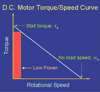
                            These graphs are from 'Understanding D.C. Motor Characteristics' – worth a read if you're interested in theory. The graphs simplify the relationships by showing them as a straight line. A real motor's characteristics would be a curve of roughly the same shape. The shape of the curve might indicate one motor to be more suitable for an application than another but that's grown-up design.

                            hitorque.jpg

                            Note High Torque occurs at Low Speed, and that power output in this condition is Low. As the excess input power has to go somewhere it appears as heat. A motor stalled for too long is likely to burn-out.


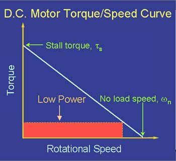
                            Next graph shows that both torque and power output are also Low at maximum speed, putting a limit on the maximum speed to which the shunter can be pushed.

                            noload.jpg

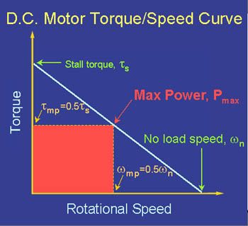
                            So, ideally, an electric motor should be operated somewhere in the middle, where torque and speed combine to produce maximum power. Where necessary a gearbox is used to ensure this happy condition.

                            maxpower.jpg

                            The good news is that:

                            • Four motors of the same make and size will have similar characteristics that, on average, will allow them to work together well. This is very different to fitting four different motors and hoping for the best. It's important that the motors match as a set, which yours do.
                            • In practice, only enough torque is needed to start the loaded shunter. Once moving, the motors will tend to move towards the sweet spot where they deliver maximum power/efficiency. (Quite likely this will be near your intended cruising speed because you calculated how to convert motor speed to axle speed)
                            • As the shunter isn't a race car, the motors you have available should comfortably support its intended purpose.

                            My only worry would be if the shunter was operated like a real shunter, that is continually start/stopping heavy loads in a marshalling yard. In that case the design would need beefing up, for example with gearing down and fan cooling the motors.

                            Bottom line, it should work as you have it.

                            Dave

                            Edited By SillyOldDuffer on 23/05/2018 10:42:18

                            #355027
                            Neil Wyatt
                            Moderator
                              @neilwyatt
                              Posted by Ron Laden on 20/05/2018 09:11:49:

                              Morning guys,

                              I am trying to get my head around choosing the correct compression springs for the loco. There will be 4 springs, one sitting vertically above each axle box. The loco and leisure battery will total 28kgs and I would like the 4 springs to be just starting to compress with that load, leaving the rest of the compression to deal with the humps and bumps of the track.

                              Is it as simple (doubt it) as 4 x 7kg springs or doesnt it work like that, I know nothing about the workings of compression springs…?

                              p.s. I guess my question is does a spring rated at 7kg support 7kg,s without compressing or is it fully compressed at 7 kg.

                              Regards

                              Ron

                              Edited By Ron Laden on 20/05/2018 09:30:15

                              Spring rate is typically the force to compress a spring by one inch (for values in pounds) or 1mm (for values in kg)

                              With a 7kg load a 1kg spring rate will give a 'sag' of 7mm, which is probably about right.

                              Assuming that in normal use the weight transfer you might expect is for 75% of the weight to be shifted forwards or aft as you go over a bump, brake or accelerate hard. That would put 10.5 kg over one each of set of wheels and 3.5kg on each of the other two wheels.

                              The springs at one end would compress by another 3.5mm and expand by 3.5mm at the other.

                              This seems to be in the right ball-park for 5" gauge but may be a bit too soft, but 1kg or 2kg rate springs could be a good start.

                              If the springs are too hard the loco may struggle to keep good adhesion or risk derailing. If it is too soft, it will bounce all over the place and may 'surge' back and forth when pulling hard.

                              You may find you need to experiment, I had to fit slightly stronger springs to my shunter.

                              Neil

                              #355037
                              Ron Laden
                              Participant
                                @ronladen17547

                                Thank you Ian, Dave and Neil that is a lot of interesting information and certainly made things a lot clearer.

                                Dave, although the model will have a shunter type body it wont be operated as one. The track it will run on is elevated with no points and no sidings. This is my first scratch build and the aim is to produce a small run around loco which hopefully is capable of pulling myself and our two young grand daughters. The shunter type body is mainly due to it being quite easy to produce and with a bit of detail it should look half decent.

                                I appreciate that testing the motors with no-load doesnt really show much but I was interested how close they were and also to check that none were faulty.

                                Neil, thanks for the spring info, I have some springs but I think they may be a bit on the light side. Once I get the chassis built (still waiting for parts) I will be able to try the springs and go from there. I guess there is going to be some trial and error experimenting here.

                                Regards

                                Ron


                                Edited By Ron Laden on 23/05/2018 14:45:27

                                #355246
                                Ron Laden
                                Participant
                                  @ronladen17547

                                  One of the problems with producing a 5 inch single battery 0-4-0 or 0-6-0 loco is the dimensions of the battery which dictates the size of the loco body. My 12V – 75 amp leisure battery measures 260 mm long x 175 mm wide x 225 mm high. The length is not generally a problem but the width is and the height even more so. I guess thats why most of the small single battery loco,s you see are square boxy diesel types as the body can be modelled to something like the correct dimensions around the battery.

                                  This is the way I have been thinking but yesterday I wondered if a lookalike steam type loco would be possible. I looked at the dimensions of one or two pannier types but there is no way you can get any where near correct dimensions when considering housing the battery.

                                  So below is a rough sketch of what I came up with, its a millions miles from anything scale or realistic and looks more like something from the Thomas the Tank shed. The broken line around the centre is the area needed for the battery. I tried to visualise it finished and I think it could be fun. Seeing as my two main passengers will be our two great grand daughters, I think it could go down quite well with them. I have not decided on it and it may still be a diesel type but its food for thought.

                                  Scale guys look away now…surprise

                                  dsc05939_edited-1.jpg

                                  #355262
                                  Jeff Dayman
                                  Participant
                                    @jeffdayman43397

                                    Maybe worth a thought to put your battery in a scale wagon coupled behind the locomotive. That would enable a more scale steam outline for the locomotive if you want it. Weights (like lead or steel plates or shot) could be added to the locomotive to help with adhesion in the absence of the battery.

                                    #355270
                                    Ron Laden
                                    Participant
                                      @ronladen17547

                                      Thats a very good idea Jeff I never gave that a thought.

                                      To be honest if I go with a steam outline something "cartoon scale" will be ok, as I mentioned the grand children will like it for sure. Since I posted though I googled images of small steam loco,s and there are a few which would probably house the battery and be in or near to scale, so those may be worth a look.

                                      Thanks again for your suggestion.

                                      Ron

                                      Edited By Ron Laden on 25/05/2018 13:31:28

                                      #355352
                                      Jeff Dayman
                                      Participant
                                        @jeffdayman43397

                                        You're welcome Ron.

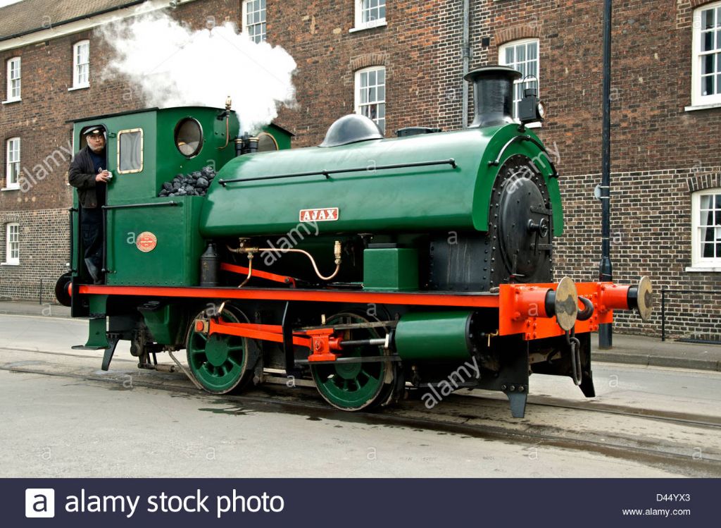
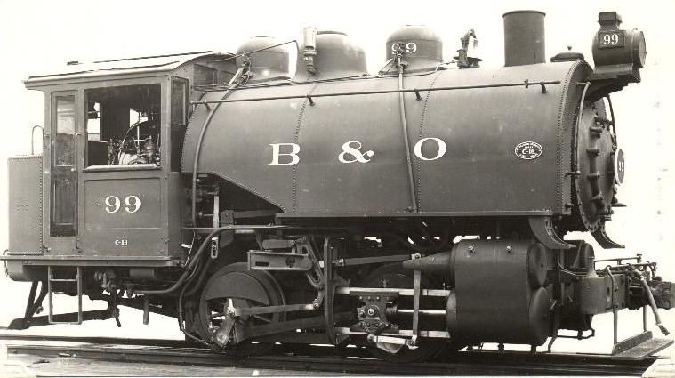
                                        Couple of further thoughts – maybe a saddle tank style steam loco outline would allow more room for the battery, if you wanted to keep it in the locomotive. A couple of pics of saddle tank engines from the internet are below, one engine from the UK and one from the Baltimore and Ohio Rwy in USA. The saddle tanks hold the engine's water supply on full size machines just FYI in case you weren't aware.

                                        Again just food for thought.

                                        ajax-saddle-tank-steam-locomotive-with-driver-working-at-chatham-historic-d44yx3.jpgb&o-saddle-tank.jpg

                                        #355385
                                        Ron Laden
                                        Participant
                                          @ronladen17547

                                          Thanks for those Jeff, I like the Ajax and I think it would house the battery ok.

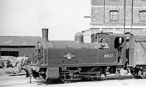
                                          I also found a Deeley 0-4-0 which could also work with the full depth tanks.

                                          deeley.jpg

                                          #355423
                                          Ron Laden
                                          Participant
                                            @ronladen17547

                                            I,m undecided at the moment but "if" I fixed the wheels to the axles using Loctite 603 retainer how difficult would they be to take apart should I need too.

                                            I was thinking maybe some heat and a gear puller, would that work…?

                                            Ron

                                            Edited By Ron Laden on 26/05/2018 11:42:28

                                            #355462
                                            Jeff Dayman
                                            Participant
                                              @jeffdayman43397

                                              Usually a good heat up and pull off works fine to release loctite. A gear puller you can get behind the centre hub, as close to the centre of the hub as possible, will help, and reduce risks of broken spokes.

                                              #355480
                                              Ron Laden
                                              Participant
                                                @ronladen17547

                                                Thanks Jeff, I have solid wheels so if the gear puller is needed it should be fine.

                                                Ron

                                                #356133
                                                Ron Laden
                                                Participant
                                                  @ronladen17547

                                                  Well, having no machining facilities (except for a small pedestal drill) and having to wait for friends to produce parts for me really tested my patience. Of course I,m not complaining about my friends, it is good of them to offer to make the bits and I wasnt going to chase them. The frustration is not having the kit to make the parts myself and in particular turned parts. I have some of the parts but still need some more and I havnt troubled anyone for them.

                                                  So I have decided to get myself a small (mini) lathe. One of the reasons I dont have one is I havnt had a place to put it or at least a place where it could be set up and left. However we cleared out and emptied a small garden shed today and the wife suggested I used it as a workshop. Now it is small, 6 ft x 4 ft but standing in there I thought a bench down the long side and across one end, would easily take a mini lathe and my bench drill and leave some space for assembly. I will have to move the shed and it needs a new base, insulating and of course electric.

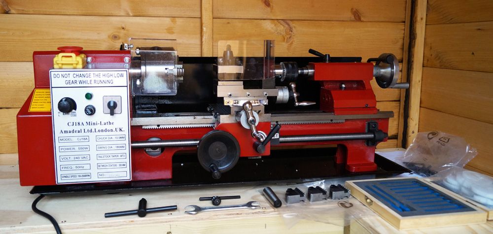
                                                  The lathe I am considering is the CJ18A 7 x 14 from Amadeal. They do it as a package for £785 with a 100mm – 3 jaw and a 100mm – 4 jaw, fixed and travelling steadies, quick change tool post with holders, face plate, live centre, tail stock chuck, measuring kit, lathe tool set and a few other bits. From what I,ve seen that seems quite good value.

                                                  I have watched a lot of youtube videos on how to set up and improve a mini lathe as they all seem to need some work to get the best out of them. Now I am never going to be trying to produce a scale steam locomotive but if I can produce the parts I need for simpler projects then I will be happy.

                                                  Ron

                                                  p.s. I forgot to say, the thought of getting a lathe…..well lets just say I,m a bit excited.

                                                  Edited By Ron Laden on 01/06/2018 19:46:01

                                                  #356791
                                                  Ron Laden
                                                  Participant
                                                    @ronladen17547

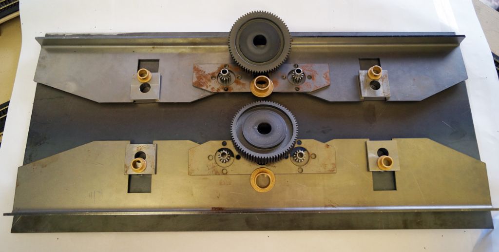
                                                    Well at long last some of the parts are coming together, they still need further work but at least its jobs I can do. I have the chassis top plate, the chassis side frames, the axle boxes and the motor mount plates. The spur gears have had the gear boss reduced and the motor pinions have been shortened and machined ready for pressing on the motor shafts.

                                                    I was very lucky with the side frames and motor mounts, I asked a friend if I could buy some 3mm steel from the engineering company he works for and he asked me to give him the drawings and dimensions. To my complete surprise he turned up a week later with the parts all laser cut. He wouldnt let me pay for the parts but said I owed him a couple of pints….I think a very good friend indeed.

                                                    dsc05943_edited-1.jpg

                                                    #358367
                                                    Ron Laden
                                                    Participant
                                                      @ronladen17547

                                                      Well at long last the minilathe is in situ, its the first time out of its box since it arrived. It was well packed and banded to a pallet and there are no signs of any damage.

                                                      I,ve had very little time today and apart from a quick start up to check it runs that was about it. Tomorrow I will clean off the protective gunge and check everything through.

                                                      dsc05953_edited-1.jpg

                                                    Viewing 25 posts - 26 through 50 (of 135 total)
                                                    • Please log in to reply to this topic. Registering is free and easy using the links on the menu at the top of this page.

                                                    Advert

                                                    Latest Replies

                                                    Home Forums Locomotives Topics

                                                    Viewing 25 topics - 1 through 25 (of 25 total)
                                                    Viewing 25 topics - 1 through 25 (of 25 total)

                                                    View full reply list.

                                                    Advert

                                                    Newsletter Sign-up