be nice to clear up something…..living out in the sticks……I understand the 4cable system from pole to pole…..3 live and 1 neutral……BUT more and more I'm seeing just three wires between poles……we are talking thick heavy wires along country roads……….where is the neutral, do they use one phase as a neutral return ?????? As 240v needs a neutral what do they then use on this 3wire system……just need to get my head around it……thanks…….Clogs…..
The power distribution system will almost certainly be at a higher voltage than 240 volts so a transformer will be required near the point where the power is used. The transformer primary will be delta wound so no neutral is required. The secondary can be star wound which provides a neutral. This neutral will probably be connected to earth at the substation. It could also be connected to earth where the power cable enters the building which it is supplying. The exact way it is done may vary between countries.
Darn good question. I think I agree with Les. In a balanced 3-phase system (star or delta) there is no neutral current. I think the power distribution network relies on the fact that spread across many consumers the phase currents should average out to be similar and therefore neutral currents, such as they are, can be ignored. Overhead cables on pylons are 132kV and upwards. It's mind boggling that people work on these cables live. The lower telegraph pole based networks are usually 11kV, or possibly 3.3kV. So, as Les says, there will be a local transformer for final distribution to consumers. For isolated properties you sometimes see a small transformer on the pole itself. I'm pretty sure my feed is overhead and the (large) transformer is down the other end of the road.
Looking at my 3-phase input in the workshop it isn't clear what comes in, as the cable is sheathed. On the other side of the electricity board box are three outputs to the meter each with a 100A fuse, ie, the three phases. There is also a fourth wire coming out, which also goes to the electricity meter. But that wire is also connected to an unshielded metal "chocolate" block which carries earth wires. So effectively the neutral appears to be earthed locally.
I've got some vague notion that the incoming cable might be three wires plus a metal sheath – it's buried in the ground, but not in a conduit. So possibly the metal sheath acts a local neutral/earth. In theory they should be at the same potential anyway.
On pylons you see a thin wire running along the very top. I think that this is some sort of protective earth against lightning strikes.
The cables on the poles that you see with only three wires may be carrying a voltage that is quite a lot more than 240 volts. The connection between them and your house system will have a 3 phase transformer in it. It will be a delta star connection requiring only three connections on the primary or incoming side, but the outgoing side will have four connections. Neutral is the star point, the other connections are carrying a voltage. There will be 415 volts or thereabouts between any two of these three connections, but 240 volts or thereabouts between one of these three connections and the star point which is your neutral. This comes out of the mathematics behind the system. A group of houses will have one live connection and the neutral connection, the next group a different live connection and the same neutral, and the third group the third live connection and the neutral. This is to try to balance the load properly.
This would be easier to explain with a drawing, but I do not know how to get one in this post.
Three phase generation and distribution of electrical energy has been standard for nearly a century in this country, but it took another forty odd years to get everyone off whatever they had had, and the number of different systems was large. As late as the 1960's I heard of premises having to have special equipment to cater for this, and the Savoy Hotel in London had a DC supply. Close by was the headquarters if the Institution of Electrical Engineers.
I took some time to post above and then had to do something else.
Back to the problem. Andrew is describing 'Protective Multiple Earthing'. The neutral point at the transformer is connected to earth through a reactor, basically a coil of cable acting as an inductance to limit fault currents. At each premises the neutral is also earthed. This gives safety if all earths are good, but can cause problems if some are not good. Years ago I spent a couple of hours with an electrician trying to find a fault in a laboratory that I worked at. The neutral was floating quite a few volts above earth. That turned out to be a loose connection in a socket.
The thin cable at the top of pylon lines is lightening protection. It ties the pylon structures together and to earth. However it is not effective when solar flares hit the Earth, inducing currents in grid cables.
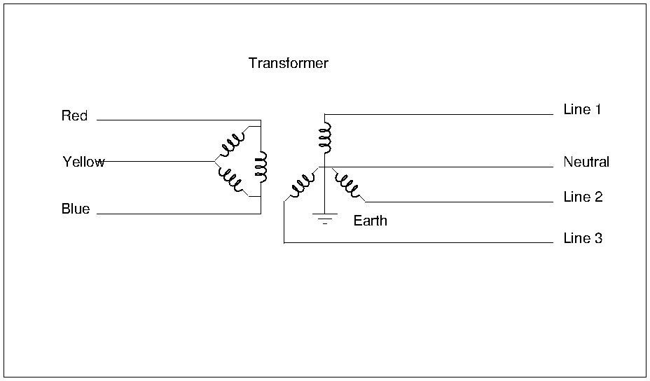
The trick is in the transformer which has six windings. Three wires arrive on the left where the transformers primary windings are connected in a triangle. As the arrangement looks a bit like the greek letter Δ, it's called 'Delta'. The three-wire arrangement is excellent for distribution. It's self-balancing and minimises the amount of wire needed.
For most domestic purposes 3-phase is a pain in the bum. Most appliances work well with the single phase. This is provided by the transformer. On the secondary side (right side of diagram) the three windings are connected as a star. The centre point is neutral and it provides a return path for 3 separate single phase lines. Usually these are kept well apart because the 'Lines' are at different potentials to each other, but the wiring still allows three-phase customers access to all three phases.
The 'neutral' is not really neutral either. To reduce the danger of electric shock the neutral point of the star is earthed at the substation. As we, our homes, and the neutral are all earthed, the neutral wire isn't dangerous even though it carries the return current. This is clever stuff: the effect is that only one wire in the home is 'hot', and that can be rendered safe with a fuse. Also, very small leaks to earth can be detected and used to break the circuit.
Of course it can go wrong. Getting across two of the Line wires will hurt because they are not at the same potential. Neutral ceases to be neutral if the earth connection fails at the transformer. Breaking the neutral wire on the supply side can have 'interesting' effects too.
The main advantage of three phase is that for three wires rather than two you can transmit three times the power. In a balanced system line to line voltage is the square root of three times the phase to neutral voltage.
Nowt to do with the number of conductors, but balance is important and is the reason why there is a limit to the size of any renewable energy generation feeding back into the grid from normal domestic properties – if all on one leg were generating into the network and all on another leg were consuming a lot of power, it could upset the system balance. An extreme example, but presumably with the limit of domestic generation the problem will not occur.
As has been said the 3 wires could be the 3 phase lines only but normally at 6kv, they could just as well be 2 x 240volt lines and a neutral, this provides 480volts between lines for farm or factory electrics. Probably not as common now as in past years but was very common when I started working in the late fifties.
Well many thanks…..you have made it quite fathomable now…….
I was always taught that 3 phase was a "black art" …..he,he………
Because I'm looking for a place that will need a 3 phase supply, (not alway's supplied as standard) the three wire system was making me loose sleep….it's alway difficult to explain what you want and then in another language and now I have a further understanding of how it goes I feel a lot better….when I first visit a property I look at/for the power lines, usually overhead…..I don't want a place without 440volt……Madame looks at the house and all the silly bits, all I care about is the site for the new workshop and if you can get an Artic down the driveway ……Simples…..
I worked in Saudi for a number years for a large American oil company which of course used 110 volt the secondary star winding was even more complex in that each leg had a centre point so you could get 110volt as well as 220.
On another point due to the high dust content in the air the pylon insulators use to track across when the humidity rose, quite a sight. They had a helicopter equipped with a washing unit and would wash the insulators with lines hot, i believe the liquid was a silicon based material.