3D printing a conrod

Advert

3D printing a conrod

Home Forums 3D Printers and 3D Printing 3D printing a conrod

Viewing 21 posts - 1 through 21 (of 21 total)
  • Author
    Posts
  • #610607
    lee webster
    Participant
      @leewebster72680

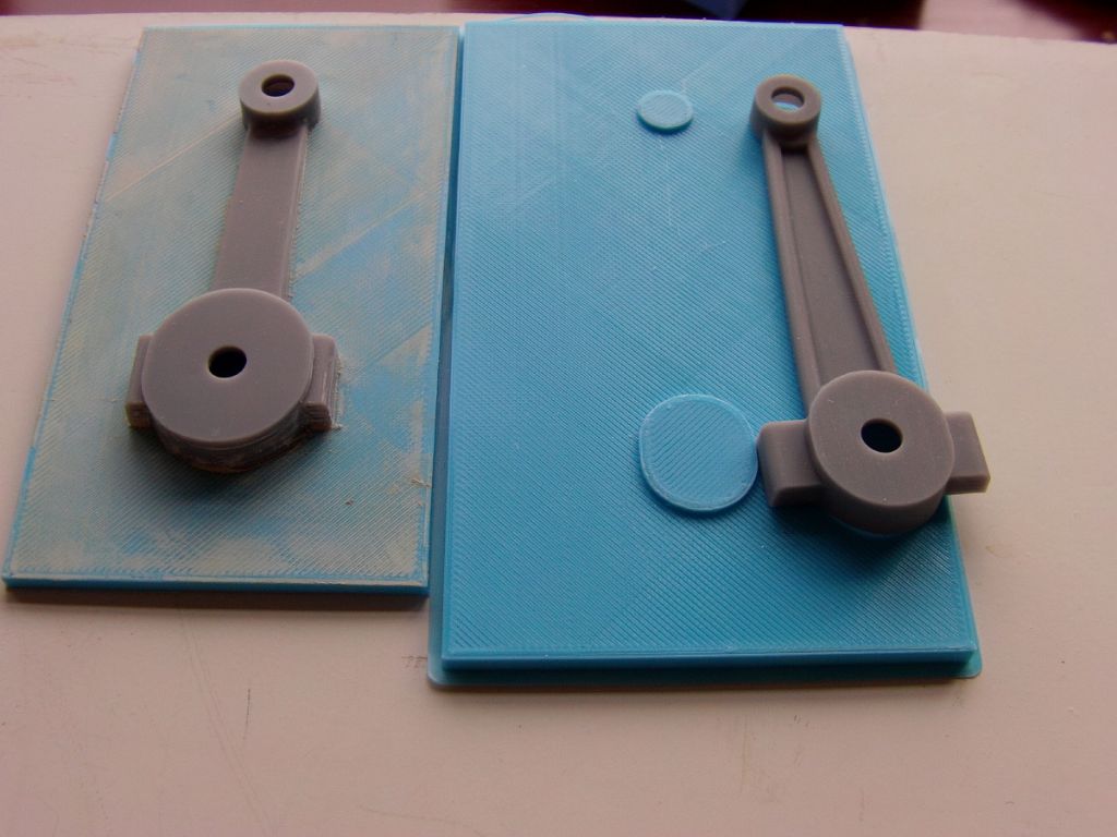
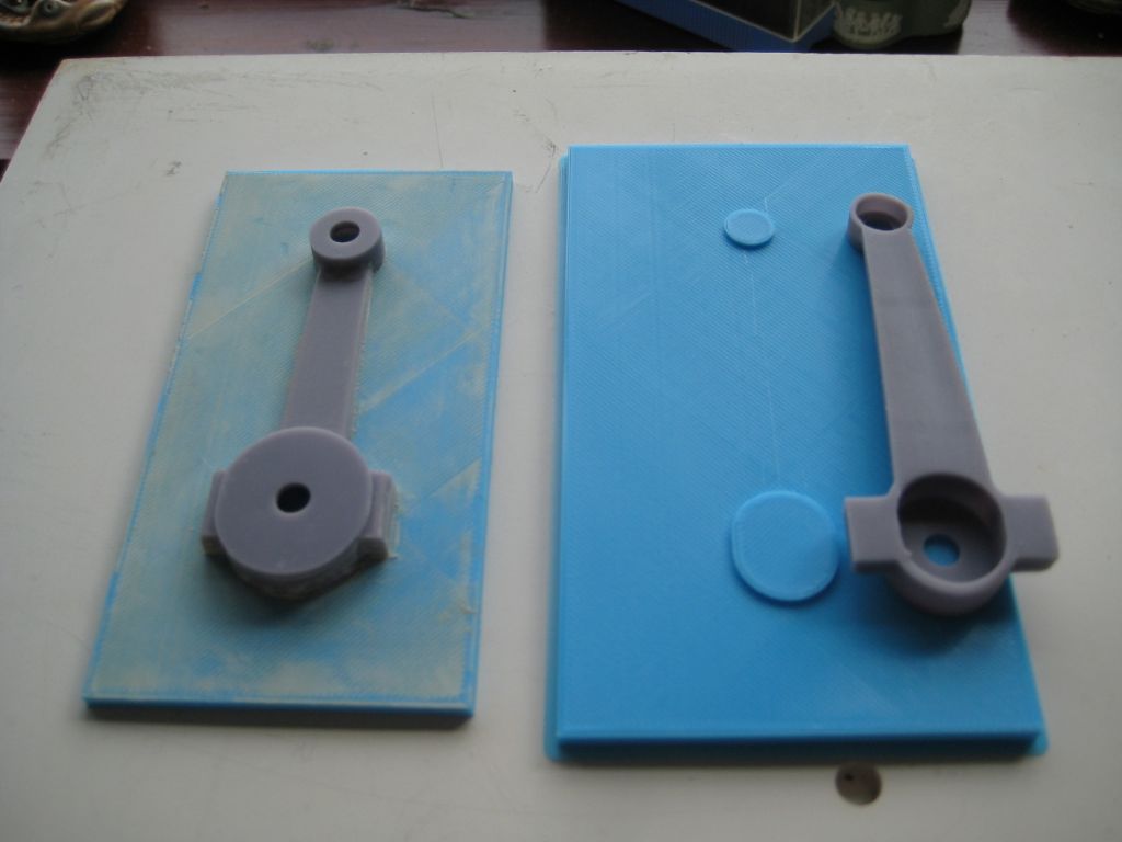
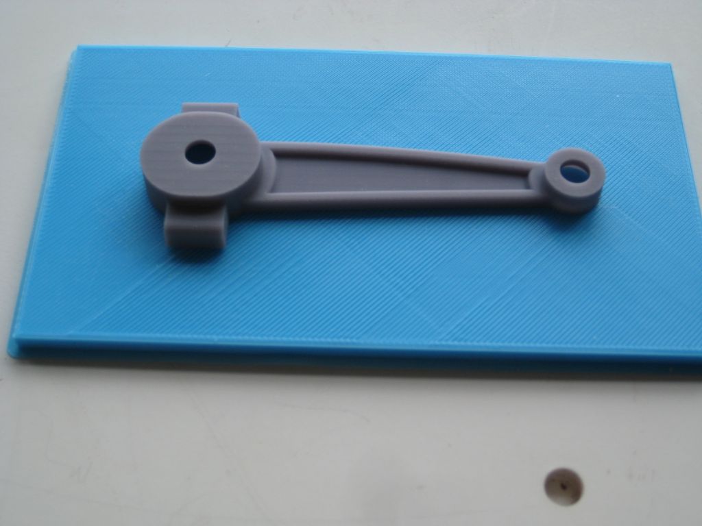
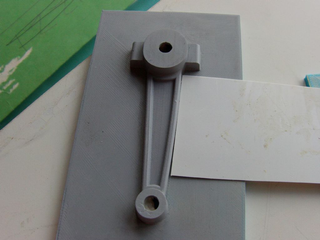
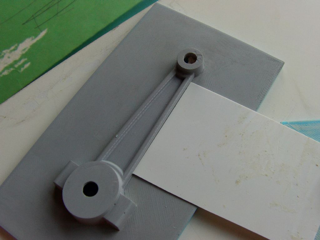
      I have 3D printed a conrod pattern with my resin printer and a baseplate to fix it to with my Ender3. I will have to fill the layer lines in the plate then I can glue the conrod to it. I will make a frame to go around the plate high enough to make a sand mould. Either resin bound sand or sodium silicate, not sure which so I should try both. I used the Ender3 to make the base as I am unsure about printing a large flat surface on the resin printer. The base has two raised bosses to locate the conrod which is partially hollow on the back. The conrod is 89mm long with a 6mm dia hole in the little end and big end. An earlier attempt at making a pattern this way is also shown. I still have to figure out how to get the molten metal, aluminium, into the mould. The conrod will be visible on the engine I am hoping to make. The big end is elongated by 3mm to allow the casting to be cut.imag0001_1.jpgimg_2068_1.jpgimg_2071_1.jpg

      Advert
      #31711
      lee webster
      Participant
        @leewebster72680
        #610620
        JasonB
        Moderator
          @jasonb

          I think I would not worry about the two hole sand have your feed riser central to the big end and a decent size to feed the casting as it cools the other riser would be central to the small end and need not be so large. This also means that you won't have any runners to remove from the unmachined surfaces.

          Oil bound would probably be easier for a first attempt as if you muck things up you can just ram it up again.

          Don't forget a couple of location pegs on the edges of your boxes so the two halves will line up.

          #610623
          lee webster
          Participant
            @leewebster72680

            Hi JasonB,

            I have only made one pattern. My idea being that I would produce two halves of the mould from the one pattern and bond them together. I have seen it done on another thread, the McDonald tractor. That's why I decided to use a bound sand rather than a rammed sand. And because I made the conrod pattern in resin, it is nowhere near as strong as the PLA print from a printer like the Ender3 and would probably be destroyed with ramming. I had toyed with the idea of feeding at the big end and have a feeder/riser at the small end. I also wonder if I should try to incorporate a pouring basin.

            I am hoping that because I have placed the conrod in the exact middle of the base the two halves of the mould should line up. I hope!

            Edited By lee webster on 21/08/2022 16:29:13

            #610643
            PatJ
            Participant
              @patj87806

              Somehow I got a duplicate here.

              Edited By PatJ on 21/08/2022 19:35:46

              #610646
              PatJ
              Participant
                @patj87806

                A few notes on bound sand.

                Resin bound sand is pretty difficult to find, and you have to use it with very dry sand (sand that has been baked to drive off the moisture, so I am told).

                Sodium silicate binder is much easier to find, and does not seem to require a commercial chemical respirator like the resin binder does.

                Sodium silicate sand is very sticky, and so use plenty of wax on your pattern.

                I am not sure if your rod ends have draft on them, but they would probably need 3-5 degrees draft.

                Sometimes you can get away with little or no draft with bound sand, especially if the pull is short.

                I suspect the big end will solidify last, and so without a riser at the big end, you will have shrinkage there.

                Normally any two surfaces at 90 degrees need a fillet, to get a clean pull from the sand mold.

                I am not seeing any fillets, and so that could be a problem.

                Many home foundry folks use the mold cavity as a runner. I consider this not an optimum method, but people do use it; it can work; and it minimizes the crucible and melt size required for a given part.

                I have often heard that the gate should enter the largest part of the casting.

                You could try a gate on the big end, and let it feed big end to small end.

                I would slant the mold so that the small end is elevated a bit, so the mold fills up towards the small end.

                I would use a small vent hole on the small end, and perhaps on the big end, with the vent hole going out the top of the mold.

                Be sure to clamp or weight the mold, so hydralic pressure does not force the cope up off the drag.

                A second approach would be to have a runner parallel to the rod, with a long knife gate into the thin part of the rod. This approach required more melt metal, and perhaps a larger flask, and I am not sure it would work correctly, given how big the ends are.

                Good luck.

                P.S. – If you use sodium silicate sand and CO2 to set it, be sure you don't over-gas the sand (5 seconds of gassing only).

                P.S. 02 – I don't use a pouring basin, as they seem to aspirate air.

                Sometimes I use a metal ring above the sprue, to make a pouring basin of sorts.

                Keep the lip of the crucible as close to the sprue opening as possible, perhaps even letting the crucible touch the sand (don't break off the sand though). Fill the sprue as fast as possible, and keep it full during the pour, without interruption. Practice pouring water if you need to refine your technique (its not a linear thing; you pour faster at first, and then the flow slows down when the sprue is full).

                Watch for when the vent holes fill up with metal, and be ready to stop pouring when you see metal come out of the vent holes.

                Keep the sprue as short as possible so as to keep the metal velocity as low as possible.

                .

                P.S. 03 – I use a foundry cement to seal the cope to the drag, when using bound sand, to prevent runouts.

                Pour temperature should be around 1,350 F (732 C).

                .


                Edited By PatJ on 21/08/2022 19:39:42

                #610648
                lee webster
                Participant
                  @leewebster72680

                  PatJ, I have been calling it resin bound sand. What I mean is fine sand mixed with epoxy resin. I know it has been used as a core mould, I will try it as a mould for the pattern. The sodium silicate is the other method I will try.

                  All the points you raised have been added to my list! Thanks.

                  Lee

                  #610653
                  PatJ
                  Participant
                    @patj87806

                    The resin binder I use is an alkyd phenolic resin.

                    There are ester-cured-phenolic resins, phenolic-polyurethane resins, and many more, so while I don't know exactly what epoxy is, my guess is that it may work ok.

                    I have seen some try epoxy as a binder, but never heard back on the results.

                    Keep in mind that the resin binders have a "set" time, and a "strip" time.

                    The set time means the mold has hardened, but not completely, so keep it on a flat surface for a while.

                    The strip time is when you remove the pattern from the mold.

                    If you exceed the strip time by too much, the bond is too strong, and you have basically permanently glued your pattern into your molding sand.

                    I use a 3-part resin binder, which is resin/hardener/catalyst.

                    The bulk of the binder is resin, which is 1.5% of the weight of the sand mold.

                    My hardener is a lesser amount, which is 20% of the weight of the resin.

                    The catalyst is optional, and can be used to adjust the set time anywhere from 1 hour or more, to 5 minutes.

                    So perhaps an amount of epoxy slightly more than 1.5% in your sand ?

                    The epoxy I have seen in liquid form is usually mixed 50/50 (1:1 ratio).

                    And with resin sand, once the mold has set, I lightly flame the interior of the mold with a gentle propane flame.

                    I would assume you would not want to breath the fumes when you flame the mold.

                    I am not positive about flaming an epoxy binder, but with a resin binder, it basically burns off any uncured resin, and gives a better surface finish.

                    I hope this info is applicable and helpful.

                    Good luck.

                    .

                    #610654
                    lee webster
                    Participant
                      @leewebster72680

                      All good information. I hadn't thought about fumes from the epoxy when molten metal hits it. I know it's been used by others in the casting process. I think it's safe to use sodium silicate in the same situation. Maybe that's the best way to go.

                      #610663
                      David George 1
                      Participant
                        @davidgeorge1

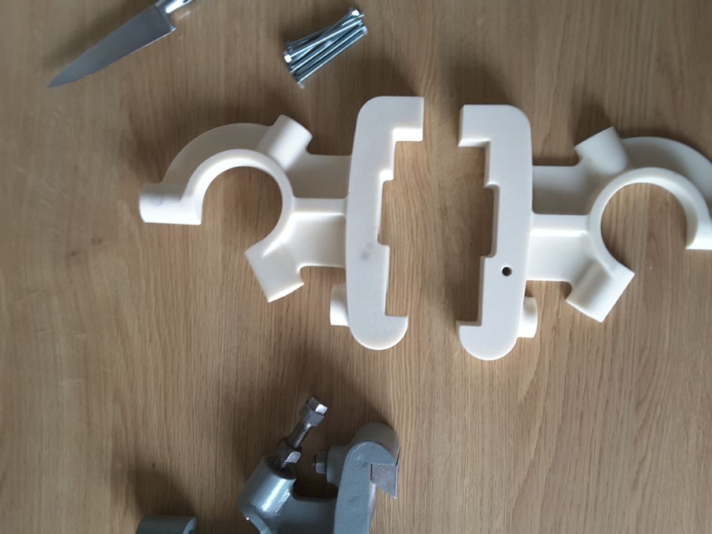
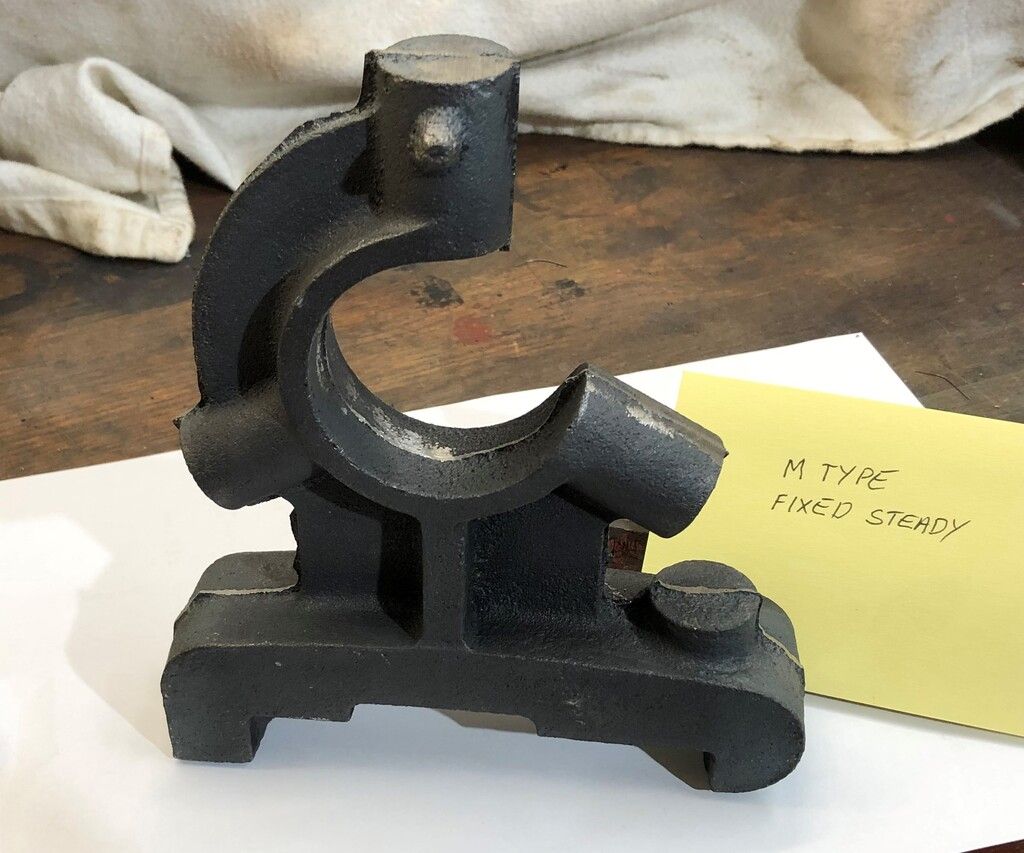
                        Hi Lee here is a pattern for a fixed steady on an M Type Drummond lathe I had made recently.

                        20220204_121746.jpg

                        20220204_121803.jpg

                        m type fixed steady.jpg

                        The pattern is symmetrical along the center line with a flat face. There are pins in one side and corresponding holes in the other so that there is no need for a back plate or runners etc as they are put in as the foundry which uses a resin sand to make the mould half at a time. You put down the flat side with no pins in the mould box and the resin sand is put in and compressed slightly. The box is inverted and the other side of the pattern is put on the first. Then the risers and runners are put in and release powder is put over the split and pattern and the second half of the mould box is put on and filled with resin sand. The two halves of the mould are opened and the pattern removed and the runners are smoothed into the risers and runners. The mould is flame hardened closed and cast.

                        David

                        #610664
                        lee webster
                        Participant
                          @leewebster72680

                          Thanks David!

                          I only printed one half of the rod because I thought I could then take two moulds from it, they should match perfectly, and then glue the two halves together for pouring. Your way sounds better.I will check my part for draft, I gave it two degrees on all sides. I could increase that to say three or four just to be on the safe side.

                          Your patterns look as though they are resin printed. Did you print them at an angle or directly on the build plate?

                          I still haven't got my printer sorted yet, still trying different settings so I don't mind doing another print.

                          Lee

                          #610668
                          David George 1
                          Participant
                            @davidgeorge1

                            Hi Lee the patterns were CNC milled using a ball nosed cutter and with 3 deg draft made from a pattern grade resin block. We have done one pattern 3D printed but the foundry did not want to use them as they cause them more problems. We had to polish all blemishes out and fill and paint them. They say that thinner 3D printed patterns also bend and move over time which causes them time to sort out when they are busy.

                            David

                            #610669
                            lee webster
                            Participant
                              @leewebster72680

                              David,

                              I recently bought a resin 3D printer thinking it would help me produce better castings. I haven't tried a casting yet, but resin prints are not the solution I thought they would be. I still have an idea lurking in my head that the prints could serve as part of a casting process. I will get a bit more experience before trying it.

                              #610670
                              JasonB
                              Moderator
                                @jasonb

                                All the patterns I have made are also cast as David describes, some split some self coding. I tend to use 2degrees for visible faces bit more if it is out of sight. The airset sand used allows a bit less draft than greensand.

                                David what was the model board you used and the stepover on the CNC. I've cut from wood and they have been cast straight from that as the finish off the CNC is very good no sanding needed, same with metal patterns they don't need any other work to the surface. I tend to use 0.2mm -0.3mm stepover with 4mm and 6mm ball nose cutters.

                                I would have thought the resin printed patterns would be OK for one off home casting, durability for multiples in a commercial foundry may find them a bit lacking. You are talking about a form of shell moulding which again should be OK provided everything is symmetrical, I would mould one as you have it and then add inlet and outlet runners before you mould the second side as it will be easier than trying to cut then in the bonded sand, just a couple of tubes will do. Or print out a couple of cylinders with spigots to fit the holes in your pattern, could even flare out the top of the inlet one.


                                Edited By JasonB on 22/08/2022 09:56:11

                                #610671
                                SillyOldDuffer
                                Moderator
                                  @sillyoldduffer
                                  Posted by lee webster on 22/08/2022 08:40:55:
                                  … resin prints are not the solution I thought they would be…

                                  This is why I'm finding Lee's posts so interesting.

                                  I've found 3D-printing in PLA to range between wonderful and useless. Much depends on how good a match the technology and material are to the job in hand, and what makes the difference between success and failure isn't always obvious to me. Experience matters. In theory 3D-printing in Resin fixes several problems compared with printing plastic, but resin clearly has it's own list of pros and cons. Lee reporting his findings is most useful. Thanks!!!

                                  Dave

                                  #610675
                                  JasonB
                                  Moderator
                                    @jasonb

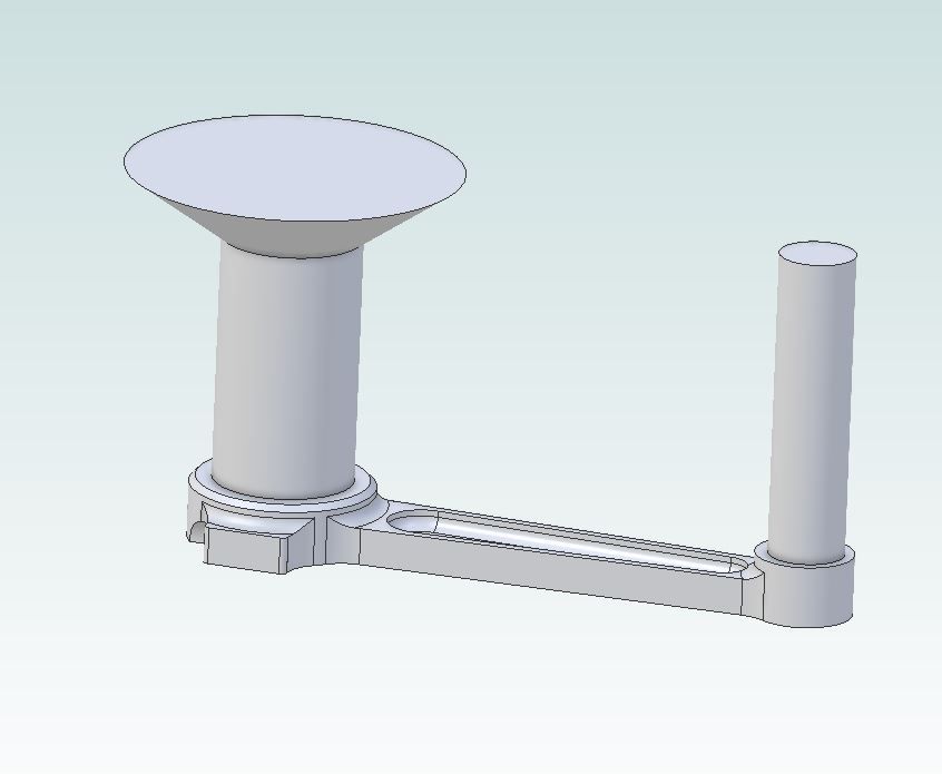
                                    Expanding on the last bit I wrote, if the second half had these gates added which could be 3D printed with spigots to fit the hole sin the pattern but left loose so they could be pulled out.

                                    conrod gates.jpg

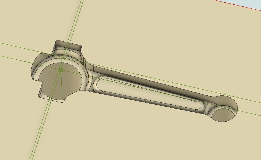
                                    Then when that half of the shell has been moulded you would end up with something like this

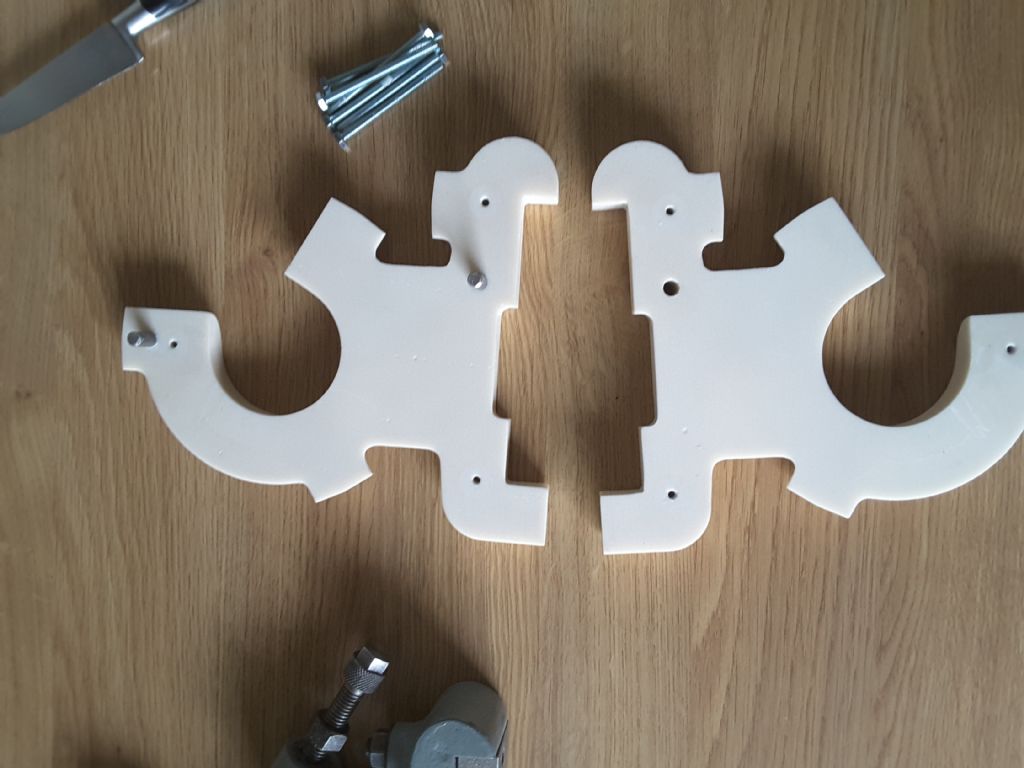
                                    conrod shell 1.jpg


                                    conrod shell 2.jpg

                                    Sit that on top of the first half and make sure they can't come apart and you are ready to pour. Probably add a small "countersink" to the exit as well so it does not overflow everywhere when full.

                                    Edited By JasonB on 22/08/2022 10:10:54

                                    #610715
                                    lee webster
                                    Participant
                                      @leewebster72680

                                      JasonB.

                                      Your thinking is along the same lines as mine. It will be a fairly easy job to print out the gates as you picture. I might try and incorporate a pouring basin, or just pour as is. Thanks for the input.

                                      Dave.

                                      Thanks for the support, it's appreciated! As you might have guessed, I am making it up as I go along. I have had some very nice greensand castings from PLA prints from my Ender3, but the time taken to get them to a good enough finish for casting seemed longer than the design and print combined.

                                      I am still learning about the correct settings for resin prints. For example, the exposure time for the general layers, not the bottom layers which need more time, is very critical. I downloaded two test pieces and printed them out. The detail is stunning. Text 1.5mm in height by a hairs thickness extruded from the surface is sharp and clear. I printed the first test print at 2 seconds exposure. Examining the details and reading the internet instructions I then set the printer at 2.5 seconds and did a second print. The improvement was very clear. I reset the printer to 2.1 seconds and printed the conrod. I think I will reset it to 2.4 seconds and try again. Getting orientation of the piece right is also important, and all these things take time. I am getting there slowly! With a layer thickness of 0.05mm ( I believe the printer can go down to 0.035mm) an extra .4 of a second adds up when there are several hundred, or more, layers to print.

                                      I have filled and sanded the base and glued the conrod to it. The glue join will need a bit of fettling before I can spray it with primer and make the surround for the casting sand.

                                      #610804
                                      lee webster
                                      Participant
                                        @leewebster72680

                                        A bit of a setback today. I had glued the conrod to the base and filled any small gaps yesterday. This morning I sanded the filler and sprayed the part with primer. This afternoon I was going to sand the primer when I noticed that the conrod had somehow become distorted.

                                        This is the gap on one side.

                                        imag0010.jpg

                                        But the other side is almost perfect.

                                        imag0011.jpg

                                        I manage to get the conrod off the baseplate without breaking it. And straightened it out with a bit of gentle heat from a hair dryer.

                                        I have now produced two files for printing. One on the Ender3 of the conrod and base as one unit, no join, at 0.12 layer height. A five and a half hour print.

                                        The other file is the same but for the resin printer. A two and a half hour print with five times as many layers.

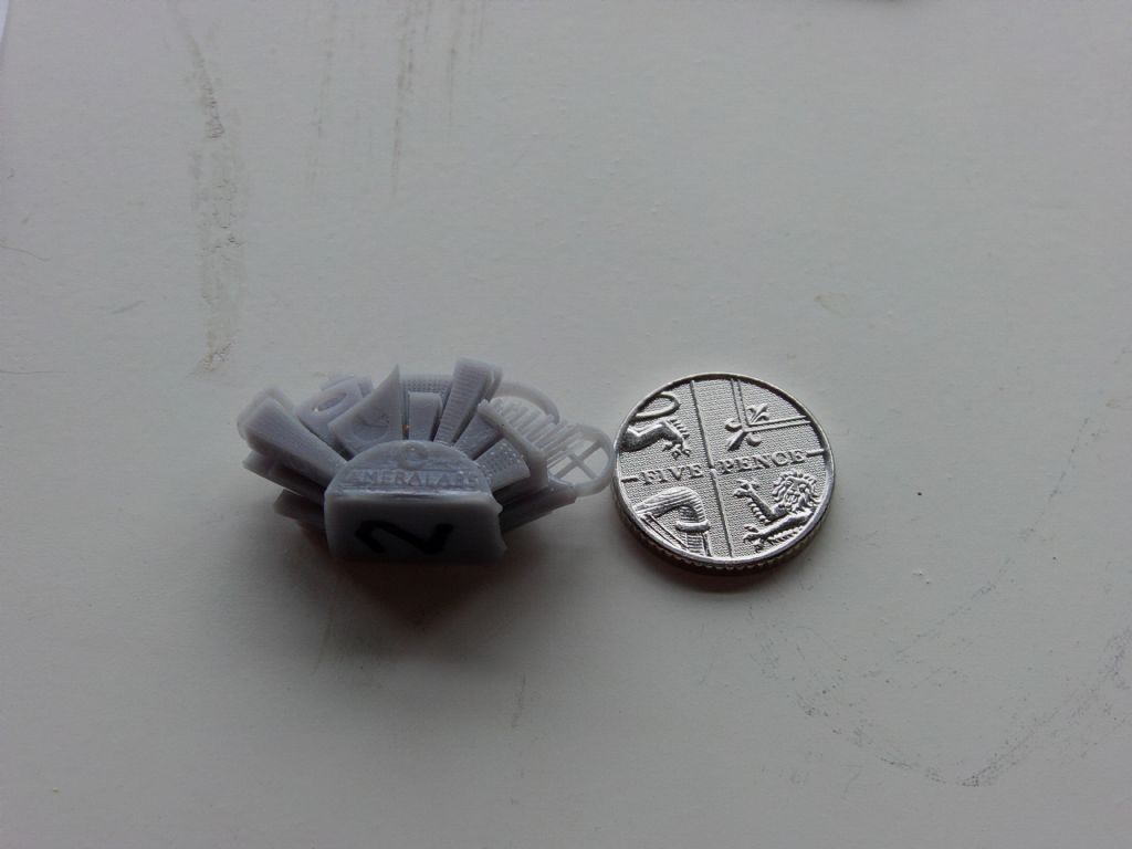
                                        This picture is of one of the test prints I did on the resin printer. The file came from a company called Amerilabs. I have included a five pence piece for scale. There are windows in the skyscrapers, I can barely see them let alone measure them!

                                        imag0009.jpg

                                        With any luck I will have both prints to work on later tomorrow.

                                        #610842
                                        David George 1
                                        Participant
                                          @davidgeorge1

                                          Hi Jason the patterns were made from glass filled PTFE sheet. They were cut by local pattern makers so don't know exact cutting information but they used a carbide ball nosed cutter. It is the local company who made patterns for the toolmakers I worked at.

                                          David

                                          #611088
                                          lee webster
                                          Participant
                                            @leewebster72680

                                            I separated the conrod and base plate and cleaned them up. I glued the conrod back on the plate and filled any gaps. That was over a day ago and the conrod hasn't distorted. I didn't paint it this time. I have 3d printed two sprues and two blanking buttons on the Ender3. The buttons will cover the 6mm holes when I fill the first half of the pattern with sand. When that half is set I will remove it from the pattern and replace the buttons with the sprues. When I get the sand to the top of the flask I can then scrape out a pouring basin in the sand around the sprue located in the big end of the conrod. When that half is set I can remove the sprues and strike the mould. I should then have two halves of a mould in set sand that can be bonded together, I think. When the mould has sat for a while I can then melt some aluminium and pour.

                                            First thing to do is to make a flask, just one half, and get the flask and conrod in the correct position on a board properly located with pins. If this method works, or rather, if I can do it properly so it works for me, it will make casting certain parts much easier.

                                            #611331
                                            lee webster
                                            Participant
                                              @leewebster72680

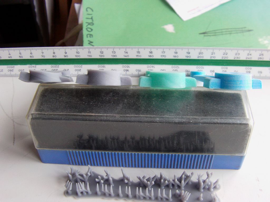
                                              I had my Ender3 and Anycubic mono printing today. The Ender3 had a slight hiccup, but managed to produce two prints with one needing some filler. The Anycubic resin printer didn't fare well, but it could be my fault. The first resin print failed with the parts being badly distorted. The second print was even worse, I had adjusted some settings and shouldn't have done. This picture shows four conrod prints. From right to left.

                                              Ender3 print, solid, fairly good. I can use this print for casting.

                                              Resin print from a day ago, hollow with 1mm thick walls, fairly good. I can use this print for casting but if I decide to try greensand then I will have to fill the hollow body with something like epoxy putty. The resin shell would be too weak for ramming.

                                              First resin print from today, solid, failed. The print is scrap.

                                              Second resin print from today, solid, failed. This print is also scrap.

                                              The supports, which partly came loose during printing are at the bottom of the picture. The conrod big ends are shown. They seemed to have the most distortion on the resin printer.

                                              I am using a water washable resin, perhaps an ordinary resin would be better?

                                              imag0022.jpg

                                            Viewing 21 posts - 1 through 21 (of 21 total)
                                            • Please log in to reply to this topic. Registering is free and easy using the links on the menu at the top of this page.

                                            Advert

                                            Latest Replies

                                            Viewing 25 topics - 1 through 25 (of 25 total)
                                            Viewing 25 topics - 1 through 25 (of 25 total)

                                            View full reply list.

                                            Advert

                                            Newsletter Sign-up