3D Printer On sale in Currys for under £1,200

Advert

3D Printer On sale in Currys for under £1,200

Home Forums 3D Printers and 3D Printing 3D Printer On sale in Currys for under £1,200

Viewing 25 posts - 26 through 50 (of 88 total)
  • Author
    Posts
  • #139558
    blowlamp
    Participant
      @blowlamp
      Posted by Peter Edwards 5 on 03/01/2014 14:48:44:

      Blowlamp – such as?!!!


      Some on here use Alibre, BobCAD or TurboCAD, whilst I use ViaCAD Pro and MoI. I also have access to Bonzai3d, but haven't really tried it yet. There are other programs too, that I'm not familiar with that seem to suit many of the people out there, judging by some of the feedback I've read.


      Martin.

      Edited By blowlamp on 03/01/2014 16:58:31

      Advert
      #139589
      AndyP
      Participant
        @andyp13730

        Phil H 1

        I got my printer with that exact intention, I cast regularly in precious metals using the lost wax technique so wanted to try a sort of lost plastic method ie burning out the printed master once invested.

        I have to say the resolution on my printer is not up to it unless you expect to machine every surface. With that caveat you could use the master as a pattern for sand casting but I have my doubts if my proposed method will ever work because the models are inherently at least partially hollow so the vacuum investing process is going to get plaster in all sorts of places it shouldn't be, It is possible to print a complete solid (well sort of) but that takes a lot longer.

        I have a Sumpod which is a reprap style machine using the usual open source software but it is constructed almost completely from 18mm mdf with flat pack furniture style connectors so is remarkably rigid.

        My major hurdle has been the 3d Cad part of the process, I have TurboCAD deluxe 2d/3d but haven't got on with it at all.

        Andy

        #139599
        Sub Mandrel
        Participant
          @submandrel

          Accepting the limitations on resolution/surface finish, some of the ideas I have had include:

          • Drumstick holder
          • Custom cable tidies/clips
          • Custom project cases
          • Telephone/multimeter/instrument holders
          • Temporary jigs for balsa models etc. (e.g. holding wing ribs upright)
          • Semi-finished parts for automatic rain gauge
          • Caddies for rechargeable batteries

          Not an earth-shattering list, by any standards.

          Neil

          Surely for sandcasting moulds, you could use hollow patterns?

          #139615
          AndyP
          Participant
            @andyp13730

            Neil,

            Sorry if I was not clear, it was my intention to say that sand casting was possible using the printed item as a pattern but vacuum investing for "lost plastic" could well be problem. If I ever manage to model something I want to cast then I will report back but don't hold your breath!

            Andy

            #139686
            Peter Edwards 5
            Participant
              @peteredwards5

              In connection with 3D printing, I think it is worth emphasising that unless you find an off the shelf 3D model file you are faced with producing your own. Unfortunately Solidworks and the like are not easy packages to use and cannot be made simpler – they must be quite involved in order to have all the facilities required. If you attempt 3D modelling of even a quite simple model you would rapidly discover the difficulties, and probably be strongly tempted to throw your computer out of the window!

              The idea that you will be able to download a file and print your part off is possible but plain daft; if it,s a standard part it would be ridiculous to have thousands of people all making their own on individual 3D printers!

              At the moment the quality of 3D printed parts is very poor, but I would guess that in about 20 yrs they will be much improved, but still only used by modellers and enthusiasts.

              #139692
              blowlamp
              Participant
                @blowlamp

                Peter.

                Give us your idea of a simple model and I for one will have a go at making it.


                Martin.

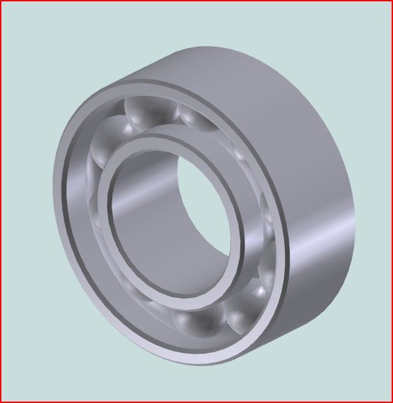
                Edit A five minute bearing video http://screencast.com/t/vFgeU5kS including making the STL file.


                Edited By blowlamp on 04/01/2014 21:47:54

                #139695
                Muzzer
                Participant
                  @muzzer

                  Some of the DIY printers are not surprisingly of very indifferent quality and capability but the semi-professional machines that Andrew Johnston and John Stevenson have bought are clearly at the top end of the range. Look at the examples they have reeled off and I think you'd agree they are better than "very poor", although it depends what you are looking for.

                  Andrew's herring bone gear set actually worked without having to be taken apart and cleaned up and the parts John made are very functional – and a pretty reasonable finish. I don't think these boys are planning on making clock parts so let's not get too sniffy. It's only a few years ago that machines costing an order of magnitude more were making parts that looked as if they were made from Shredded Wheat.

                  I wouldn't put people off having a go at 3D CAD. It may be a bit of a learning curve but once you have learned the basics of the application and done a few of the tutorials you are half way there. Bear in mind that most of us already do the other part ie visualising, designing and drawing up our parts ahead of making them. There is quite a choice of CAD applications out there, so if you try one out on a limited duration trial and don't like it you can always try another one. It's horses for courses.

                  The basic version of Alibre is now called "Cubify" with exactly this market in mind, as they also own a 3D printer company. It's actually reasonably cheap and has a surprisingly full set of features in common with the full professional version. If you like it and want to use it beyond 3D printing (ie save to different file formats etc), you can simply upgrade to the full package by buying a bigger licence key. Personally I didn't but that was for other reasons. However, if you are thinking of driving one of these 3D printers, it makes a lot of sense to take a look. You never know where it might take you…

                  Merry

                  #139713
                  Russell Eberhardt
                  Participant
                    @russelleberhardt48058
                    Posted by blowlamp on 04/01/2014 21:14:16:A five minute bearing video **LINK** including making the STL file.

                    Makes it look easy! Does anyone know what software was used?

                    Russell.

                    #139721
                    blowlamp
                    Participant
                      @blowlamp
                      Posted by Russell Eberhardt on 05/01/2014 09:39:57:

                      Posted by blowlamp on 04/01/2014 21:14:16:A five minute bearing video **LINK** including making the STL file.

                      Makes it look easy! Does anyone know what software was used?

                      Russell.

                      Yes, it is pretty easy with just a bit of practice – I used MoI to make the example video.

                      Martin.

                      #139723
                      JasonB
                      Moderator
                        @jasonb

                        Thats basically the same way that I have drawn them in Alibre (Cubify) perfectly adequate for using when doing an assembly of a model.

                        bearing.jpg

                        #139735
                        Anonymous

                          I don't know why Peter keeps saying it's difficult to produce custom parts on a 3D printer? Here are a few custom parts I've made over the Christmas holidays:

                          3d_printer_parts.jpg

                          For scale the box middle left is 50×75 mm. The idea of these parts is to test out the limits of the printer and experiment with things like wall thickness, sharpness of corners, tolerances and overhangs. That way I can learn about the strengths and weaknesses of the printer before I start designing parts for real.

                          I use Alibre (Geomagic) for 3D CAD; personally I've never had any problems with it, other than the usual hiccups you get with any complex software package. I've never used Solidworks, but have used ProEngineer in the past; ProEngineer had a very poor user interface, despite costing both arms and legs. It only takes a few minutes to go from an idea created in Alibre, through the slicing software, download to a SD card and start printing.

                          Regards,

                          Andrew

                          #139741
                          Gordon W
                          Participant
                            @gordonw

                            Can I stick my nose in, although knowing nothing about 3D printers? To make lost wax casting patterns could you use wax as the feeder and alter the temperatures to suit ? If this is stupid just erase.

                            #139744
                            JasonB
                            Moderator
                              @jasonb

                              For one offs at our level its probably easiest to use PLA and melt that out of the investment rather than have to have a separate machine capable of printing wax if you could get one.

                              For multiples the best way would be to print a master and then take a rubber mould of it which you would then use to cast as many wax patterns as you wanted which can easily be made into a tree.

                              A couple of weeks ago I saw part of a 6" scale traction engine lamp that had been printed and it was intended to use this to make waxes. The part had been produced using a printing service and the finish was excellent, you could not see any layering it looked more like an injection moulding, size was about 40mm x 60mm with 0.5mm wall thickness. This is Andy's drawing that it was printed from.

                              If layering is a problem the part can be dipped in solvent to blend the surface, MEB mag had an article about 3D printing a while back and showed the various qualities of finish bepending on cost of machine.


                              J

                              Edited By JasonB on 05/01/2014 13:25:14

                              #139745
                              John Stevenson 1
                              Participant
                                @johnstevenson1

                                Looking at it from our point of view, home workshop, sod everyone else wink the answer is prototyping or small repair.

                                Andrew has shown very well what a decent one is capable of. I am working on a bracket at the moment that will go to the foundry as a pattern for a conventional sand casting. This will be used in a production run so the plastic one is being made X 0.16, X 0.16 to give double the shrinkage allowance as the first one off will be the alloy pattern for the rest as I don't know how the plastic one would last over say a 100 piece run.

                                This scaling is a click of the button, draw full size than scale to suit the material, then print. Unfortunately I can't show any photos at this point as it's a proprietary part and many on here would recognise it.

                                I could mill this out or metal or wood but because of the shape with swept curves etc it would need to be 3D milled which is something that takes me a lot of time and retries. Add to the fact that I need lugs on to hold it whilst milling it then becomes a 3 program setup to machine all over.

                                With the 3D print I only have to draw it, the software inside the machine does the rest, Andrew has to slice his or get the program to do it, mine is built in. Then it will print all round, no lugs and actually build up supports automatically where it is needed under the unsupported curves.

                                So taking this as a time study I reckon it will take me a couple of hours to draw it, Jason and Andrew could probably do this in 1/2 hour, they have more experience of Alibre than I do.

                                Set the printer up, say 15 minutes to warm up etc.

                                Then print. without the drawing i don't know this time but I'm guessing about 3 hours, chances of a failure are low.

                                So for me 5 hours to get a pattern.

                                Now the other way is drawing, same time, then CAM to get the milling code and I reckon with my limited experience of 3D milling programs we are looking 3 to 4 hours and then milling which again guessing will be 3 to 4 hours with the 3 setups. Chances of a failure are high.

                                So double the time at least to do this conventionally.

                                #139791
                                Peter Edwards 5
                                Participant
                                  @peteredwards5
                                  Posted by blowlamp on 04/01/2014 21:14:16:

                                  Peter.

                                  Give us your idea of a simple model and I for one will have a go at making it.

                                  Martin.

                                  Edit A five minute bearing video **LINK** including making the STL file.

                                  Edited By blowlamp on 04/01/2014 21:47:54

                                  Blowlamp

                                  You are obviously competent on this package – I won't insult you by setting you a problem. I know Solidworks pretty well having taught it for many years, and all I can say is that most people have difficulties and it takes a lot of hours to achieve proficiency at even a modest level to produce acceptable 3D models and drawings with dimensions, tolerances, surface finish etc. But it's worth the effort! Simple models for 3D printing only, not manufacture as such, would be less of a problem I agree.

                                  #140019
                                  Anonymous

                                    In a PM from a member of this forum I was asked if I could take some close up shots of the surface finish I am obtaining on my 3D printed parts. That was an excuse to do some tests. I printed five 25mm cubes with varying parameters. I printed one cube with a layer height of 0.2mm and a print speed of 80mm/s. I printed three cubes with a layer height of 0.1mm and print speeds of 40, 80 and 120mm/s, and one cube with a layer height of 0.05mm and print speed of 80mm/s. In all cases the wall thicknesses were 1.6mm with a 20% diagonal fill in the middle. The top and bottom surfaces do not seem to change much, so I've only taken one picture of each. The pictures were taken with a USB microscope on x10 magnification.

                                    Here is the bottom of a cube:

                                    cube_bottom.jpg

                                    And the top:

                                    cube_top.jpg

                                    The side with a layer thickness of 0.2mm:

                                    cube_side_02.jpg

                                    Side with a layer thickness of 0.1mm:

                                    cube_side_01.jpg

                                    And side with a layer thickness of 0.05mm:

                                    cube_side_005.jpg

                                    The uneven corners are where I got impatient and tried to remove the cubes from the baseplate before they had cooled down properly. sad

                                    The cubes are surprising strong, I can stand on one without it breaking!

                                    Regards,

                                    Andrew

                                    #140022
                                    Anonymous

                                      As well as taking pictures of the cubes mentioned I also took some measurements and Ra surface roughness values (all Ra values are in µm). First, here are some basic dimensions for each cube, in millimetres and ordered as W x D x H. The cubes are identified by layer height (mm) and then print speed (mm/s).

                                      0.2/80: 24.9 x 24.7 x 25.1

                                      0.1/120: 24.9 x 24.7 x 25.0

                                      0.1/80: 25.0 x 24.7 x 25.1

                                      0.1/40: 25.0 x 24.8 x 25.1

                                      0.05/80: 25.0 x 24.8 x 25.2

                                      Generally the dimensions seem pretty consistent. Changes in layer height and print speed do not seem to have as much effect as I might have expected. It's possibly a bit ironic that the smallest layer height cube seems to have the least accurate height. I'm not quite sure why there is a difference in width and depth. I wonder if there is a slight variation in the scaling of the X and Y axes, or the slicing software has some sort of quantisation errors, or probably most likely it's a shrinkage effect. More experiments needed!

                                      For the surface roughness measurements I took measurements on the bottom, top and one side. For the top and bottom the fill is diagonal, so I took three measurements, one across each diagonal and one parallel to the sides. In the numbers below the order is diagonal one, diagonal two and parallel. For the side I took one measurement.

                                      The results are:

                                      0.2/80:

                                      Top: 17.6 8.4 13.6

                                      Bottom: 18.5 7.0 18.0

                                      Side: 13.5

                                      0.1/120:

                                      Top: 9.6 6.5 9.6

                                      Bottom: 17.6 8.2 17.1

                                      Side: 7.5

                                      0.1/80:

                                      Top: 5.5 7.4 9.1

                                      Bottom: 16.7 9.3 15.7

                                      Side: 8.6

                                      0.1/40:

                                      Top: 5.1 2.6 4.4

                                      Bottom: 17.7 1.7 18.6

                                      Side: 9.7

                                      0.05/80:

                                      Top: 5.1 2.5 4.7

                                      Bottom: 18.6 12.5 20.6

                                      Side: 5.5

                                      A few points are:

                                      1. The roughness values for the bottom surface do not vary much – not surprising, as in all cases the first layer is done with a print speed of 20mm/s to ensure adhesion to the baseplate

                                      2. As one might expect the side roughness decreases with smaller layer heights

                                      3. As a very rough comparison the roughness values are about 10 times worse than I get when turning metal

                                      4. The cubes feel a bit smoother than the values suggest, and this is backed up by 'fingernail' comparisons with a Rubert test set

                                      Make of the numbers what it you will.

                                      Regards,

                                      Andrew

                                      #140026
                                      Gone Away
                                      Participant
                                        @goneaway
                                        Posted by Andrew Johnston on 05/01/2014 12:06:07:

                                        ProEngineer had a very poor user interface, despite costing both arms and legs.

                                        I still use an old (2001) version of Pro/E and I have to agree – it's pretty user-hostile. You do get used to it in time and your speed goes up. It's very modular and has all the appearance that the modules were programmed by different groups, possibly in different countries, that never actually talked to each other. Not to mention that, in 2001, the Windows version was still weighed down with its Unix legacy and didn't always follow Windows programming standards/conventions.

                                        I have to hope that later versions were/are better. Particularly now there's much more competition.

                                        Edited By OMG on 08/01/2014 15:01:12

                                        #140029
                                        Anonymous

                                          Update: I tweaked the Y-axis scale to be bigger by 1% in the slicing software and printed another cube. Dimensions (measured in the centre of the faces) are now:

                                          25.00 x 24.99 x 25.03

                                          I didn't believe it either, but the micrometer doesn't lie! There is about a ±0.05mm variation as one gets to the edges of the faces. I wonder if some of the previous values were distorted because I didn't wait for the parts to cool down properly?

                                          Regards,

                                          Andrew


                                          Edited By Andrew Johnston on 08/01/2014 16:00:36

                                          #140033
                                          Martin W
                                          Participant
                                            @martinw

                                            Hi

                                            And for those with a sweet tooth or just feeling peckish in the workshop then here is the answer smiley.

                                            #140047
                                            Peter Edwards 5
                                            Participant
                                              @peteredwards5

                                              Andrew. Thanks for the photos and Ra values for your 3D printed cubes. They confirm that the surface finish (and dimensional accuracy) are really not too good!. I suppose it depends what you want the part for. I wonder how you got the Ra values – the equipment I used isn't the sort of thing most people have in the house.

                                              Using stereolithography produces a very satisfactoy result, but at the moment it is very expensive.

                                              I have visited PCWorld and Maplin, both offering 3D printers for sale on their web pages. At Maplin they said it was online sale only and they didn't have one in the store to show me, and at PC World I had to explain to one of the senior staff what a 3D printer was – and, no, they didn't have one!

                                              I have looked in vain for somewhere to see one working on display – I'm beginning to think it's because the results would not persuade a lot of people to buy one!. Correct me if I'm wrong!

                                              #140049
                                              Sub Mandrel
                                              Participant
                                                @submandrel

                                                I'm confused – I though Andrew's results were rather impressive? Overall dimensional accuracy of about a thou sounds good to me.

                                                It would help if it was clear what the roughness measurements were in, I assumed micrometers?

                                                Andrew, could you clarify and give a subjective assessment of whether you think this is a good or bad result?

                                                Neil

                                                #140050
                                                John Stevenson 1
                                                Participant
                                                  @johnstevenson1
                                                  Posted by Peter Edwards 5 on 08/01/2014 20:30:10:

                                                  Andrew. Thanks for the photos and Ra values for your 3D printed cubes. They confirm that the surface finish (and dimensional accuracy) are really not too good!.

                                                  I gather you have never used a Bridgeport ?

                                                  #140053
                                                  Anonymous

                                                    To clarify the Ra values are in µm, and were measured with a Taylor Hobson Surtronic.

                                                    Regards,

                                                    Andrew

                                                    #140068
                                                    Muzzer
                                                    Participant
                                                      @muzzer
                                                      Posted by Peter Edwards 5 on 08/01/2014 20:30:10:

                                                      I'm beginning to think ……the results would not persuade a lot of people to buy one!. Correct me if I'm wrong!

                                                      You're plain wrong I'm afraid – I've just ordered one like Andrew's.

                                                      I have to say they are pretty impressive straight out of the box. For most plastic mouldings and diecastings you would be lucky to even get close to these dimensional tolerances without an additional machining step – at least in the industries most of us work in. It's early days yet, so repeatability isn't known but knowing how these things work helps to explain the tolerances and suggests they should be reasonably consistent.

                                                      Muzzer

                                                      Edited By Muzzer on 09/01/2014 05:50:53

                                                    Viewing 25 posts - 26 through 50 (of 88 total)
                                                    • Please log in to reply to this topic. Registering is free and easy using the links on the menu at the top of this page.

                                                    Advert

                                                    Latest Replies

                                                    Viewing 25 topics - 1 through 25 (of 25 total)
                                                    Viewing 25 topics - 1 through 25 (of 25 total)

                                                    View full reply list.

                                                    Advert

                                                    Newsletter Sign-up