3D-CAD Package Shootout – Cotton Reel Example

Advert

3D-CAD Package Shootout – Cotton Reel Example

Home Forums CAD – Technical drawing & design 3D-CAD Package Shootout – Cotton Reel Example

Viewing 25 posts - 76 through 100 (of 113 total)
  • Author
    Posts
  • #595097
    duncan webster 1
    Participant
      @duncanwebster1
      Posted by duncan webster on 19/04/2022 15:10:59:

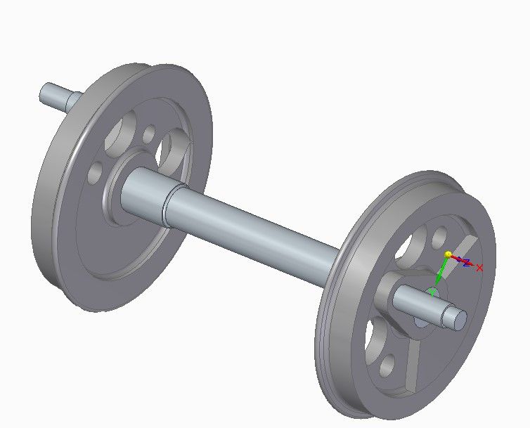
      After 3 hours of cursing I managed to work out how to align the parts, dead easy once you've twigged. I now have 2 wheels complete with crankpins on an axle (could have made them out of metal in this time!), but the crankpins are in line. I need to rotate one wheel/crankpin assembly about the x axis of the wheel. I think it might be to do with the steering wheel thing that keeps popping up, but I can't get it to align along the x. Anyone got any good ideas. I've tried and failed with Google. This is Solid Edge

      And while I'm on, I tried to copy a 2D drawing out of nanoCad into SE so I could rotate the profile, did Copy with Base Point, which usually puts it on the clipboard, but failed to paste it into SE

      Sorted the first part, again easy when you know how, move the origin of the steering wheel to a face on the x axis, at least it worked for me. Take me 4 hours so far!

      Edited By duncan webster on 19/04/2022 16:51:46

      Advert
      #595102
      IanT
      Participant
        @iant

        Hi Duncan,

        Good to see you making progress.

        The steering wheel is one way to do this but when you are setting assembly relationships in Solid Edge, you can also use 'drag component' – with a choice of either a 'move' (relative to an edge or axis), rotate (about an edge or axis) or 'freemove' (which is an unconstrained drag). You can also define the exact amount of 'drag' should you need to.

        So I think this capability would also have solved your problem – although I cannot claim to have fully mastered it myself quite yet.

        Regards,

        IanT

        #595130
        duncan webster 1
        Participant
          @duncanwebster1

          That's even betterer, thanks. Here's where I'm up to, I've also done the crosshead. No wonder I don't make progress with the metalwork!screenshot 2022-04-19 211835.jpg

          #595133
          IanT
          Participant
            @iant

            That's looking very good Duncan.

            Regards,


            IanT

            Edited By IanT on 19/04/2022 22:00:08

            #595158
            SillyOldDuffer
            Moderator
              @sillyoldduffer
              Posted by Alan on 19/04/2022 15:29:58:

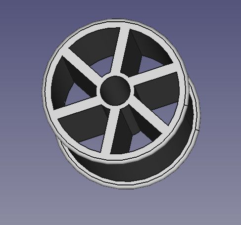
              Its taken a bit of time…But here is my attempt…

              coton_reel_screenshot.jpg

              This is a FreeCAD screenshot

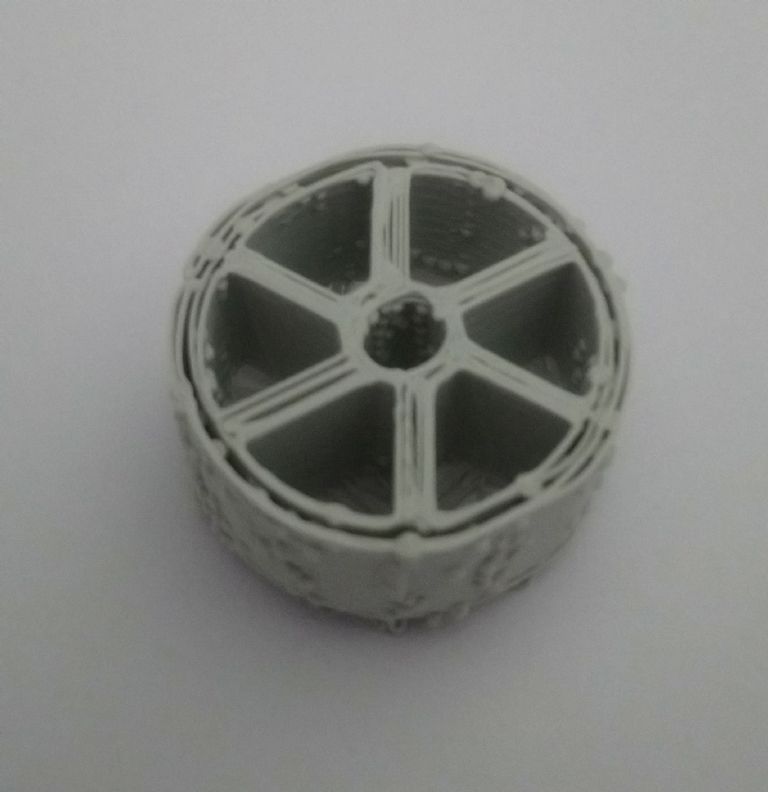
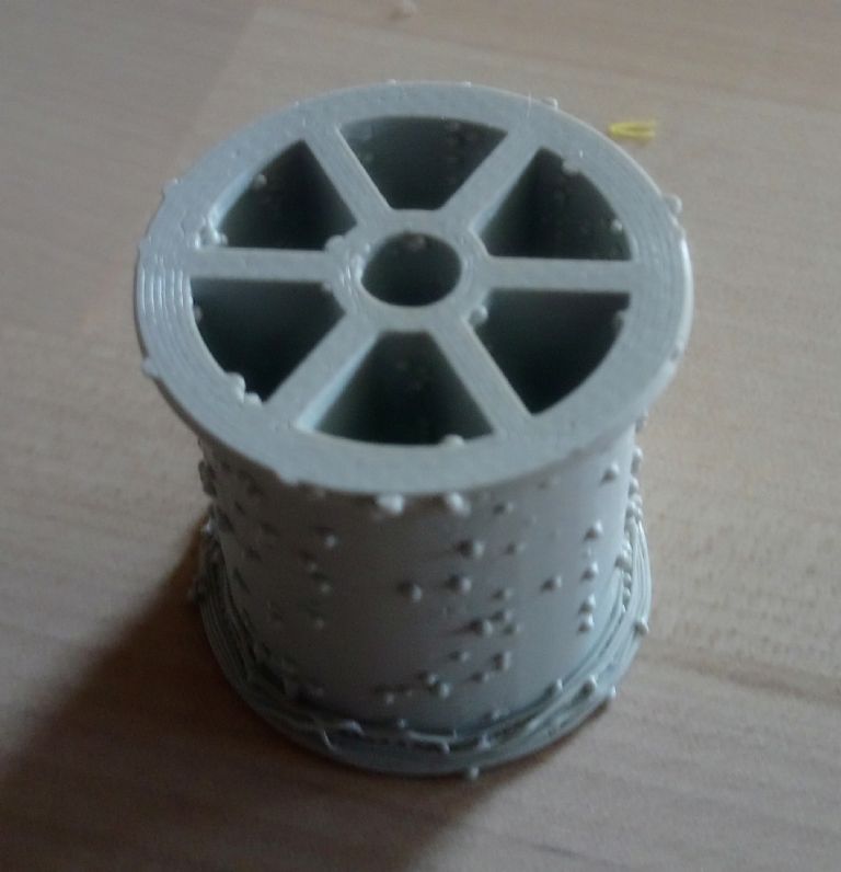
              And this is part of a 3D print…

              cotton_reel_print_crop.jpg

              Not a very good print… as I'm still trying to learn how to work the printer!!

              The FreeCAD drawing could also be improved… but I don't think its too bad for a first attempt!

              Alan

              Congratulations! No idea why the 3D-print is wonky. My Creality Ender-Pro "just works" with the default settiings, and I've never had to fiddle with it. Just as well – there are a lot of them. Cura seems pretty good at generating a reasonably strong internal honeycomb too.

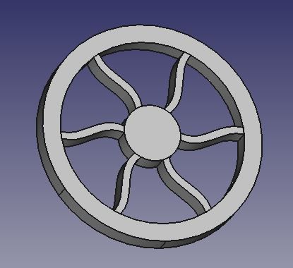
              Those staggered spokes,are slightly harder to do than straight ones, so award yourself a small prize. Reminded me of something FreeCAD struggled with in earlier versions, which now seems fixed. S-shaped spokes as used on cast-iron pulley wheels to prevent cracking as the casting cooled.

              freecadsspokes.jpg

              Dave

              #595160
              Alan
              Participant
                @alan14594

                Thanks Dave!

                The staggered spokes are an error.. (feature.?)

                I'm currently trying to get then straight!

                The method of drawing it was fairly easy…

                1) Sketch the side on profile

                2) revolve around Z axis

                3) Drill hole in centre

                4) Sketch one segment, and make the hole

                5) tell the program to repeat 6 times…

                Alan

                #595175
                SillyOldDuffer
                Moderator
                  @sillyoldduffer
                  Posted by Alan on 20/04/2022 09:09:46:

                  Thanks Dave!

                  The staggered spokes are an error.. (feature.?)

                  I'm currently trying to get then straight!

                  The method is fine, so a fine tuning problem. I share your pain, because I spent yesterday getting to grips with Solid Edge! Hitting lots of problems which I strongly suspect are due to me being on a learning curve.

                  • Big trouble with the mouse buttons which are completely different from F360 and FreeCAD
                  • Problems selectiing faces created by chopping out sketches with extract, with the software often selecting the wrong feature. The object is a complex shape. Partly fixed by using the F3 key (which locks a plane once identified), and – I suspect – by altering the 'Design Intent' settings, which control the type feature the software will select. The symptoms suggest operator error.
                  • By default, Solid Edge operates in Synchronous mode, but I think in terms of History. I think the combination may be putting me into wild untamed border territory, which can introduce geometric errors inside the software – at least one sketch had a warning message. Again, the symptoms suggest operator error.
                  • GIGO, garbage in, garbage out is a major problem in computer programming. Masses of code is written to check and validate input before any work is attempted. Problem is users are remarkably inventive when it comes to inputting garbage – who doesn't press keys and click buttons randomly in hope something will work properly! The poor old programmer has to think of every possible stupidity, which is hard! Anyway, I managed to crash Solid Edge 4 times, so it's not unilaterally solid. Given the experimental nature of my fumblings, it's not surprising.

                  Otherwise, I like the look, feel and functionality. Early days, but for slickness SE seems to sit between FreeCAD and F360. Much of FreeCAD's user interface is GUI conventional, which has a solid clunky feel that slows down the workflow. Solid Edge and F360 are more mouse driven, where faces are automatically selected, and it's not necessary to go through a dialog which speeds things up considerably. (Assuming the right face is selected – of the two F360 seems less likely to choose the wrong face and I think it's more efficient too. I need to spend more time with SE though, much of the trouble is me, and I don't think I've got my head round the implications of synchronous mode yet.

                  A few strong positives jump out:

                  • SE Community Edition appears to be Full Function for non-commercial use and has a lifetime licence. (Unlike F360 where the licence and functionality can be changed after installation.)
                  • SE works locally, not in the cloud, which is good for security, privacy and owner led control.
                  • Compared with FreeCAD, the Assembly workbench appears more usable. (But I haven't tried FreeCAD's latest Assembly4 workbench yet.) The same polish is likely true of other features.

                  Dave

                  #595411
                  Alan
                  Participant
                    @alan14594

                    Back again… with a nearly successful 3D print…

                    cotton_reel_02.jpg

                    I've now worked out how to get the six spokes straight in FreeCAD..

                    Doing the redraw didn't take as long as the print!!

                    Just got to work out how to get rid of the blobs on the print… I suspect that they occur where the extruder starts and stops…

                    Any other ideas..??

                    Alan

                    #595436
                    lee webster
                    Participant
                      @leewebster72680

                      Was it Spike Milligan or the Goons who sang a song about "Spotty Muldoon"? I don't know what made me think of that…..

                      #595494
                      duncan webster 1
                      Participant
                        @duncanwebster1

                        I've done something wrong, and I can't undo it. When I press down the scroll wheel and move the mouse, a red line appears and the model will only rotate around that line. I'm in Solid Edge, someone must know what I've done wrong.

                        And while I'm on, how do I make it draw on the ZX plane rather than the front face? It isn't actually showing the planes, I don't want to create another plane when there is already one there (presumably)

                        #595502
                        GordonH
                        Participant
                          @gordonh

                          Duncan

                          "I've done something wrong"

                          Cool, looks like you found a shortcut to pressing the rotate icon on the bottom of the window. When you say that you can't get out of it, I hope you mean that it happens every time you press the scroll wheel and not that you're locked in the rotate mode. On my SE, pressing Escape ends the rotate mode.

                          "It isn't actually showing the planes"

                          You have probably turned off the Base Planes display on the Pathfinder. On the Pathfinder display, there is an item "Base Reference Planes. If that is Greyed Out, tick the empty box to the left. Clicking the boxed "+" symbol allows you to view or hide individual planes . Similarly you can view or hide any reference planes that you add.

                          If the Boxed F3 is displaying, click it, or press F3 to unlock the currently selected plane .

                          Gordon

                          Edited to remove partial word

                          Edited By GordonH on 23/04/2022 08:07:29

                          #595504
                          SillyOldDuffer
                          Moderator
                            @sillyoldduffer
                            Posted by Alan on 22/04/2022 13:56:30:

                            cotton_reel_02.jpg

                            Just got to work out how to get rid of the blobs on the print… I suspect that they occur where the extruder starts and stops…

                            Any other ideas..??

                            Alan

                            CAD is only the first part of the battle. After the computer model is fixed, you've got to make a real one!

                            I'm no expert on misbehaving 3D printers. Blobbing might be due to the extruder being slightly not hot enough, or maybe the filament feed is sticking. Dirt in the extruder maybe – needs a clean – one website recommends Acupuncture Needles, which will appeal to traditionalists and Feng Shui metaphysisists.

                            What printer and slicer is it?

                            Might be worth starting a new thread on 3D printing problems, with a title that attracts experts in that aspect.

                            Dave

                            #595514
                            SillyOldDuffer
                            Moderator
                              @sillyoldduffer
                              Posted by duncan webster on 23/04/2022 00:34:02:

                              I've done something wrong, and I can't undo it…. I'm in Solid Edge…

                              I share your pain Duncan! I'm learning Solid Edge and finding it a roller coaster.

                              • Session 1 was more disaster than success, mainly because my beginner muddled ideas resulted in a broken model – three 'Edge Vertex rebind errors'. I like Synchonous working, but having a background FreeCAD and Fusion360 has given me a History mindset, which definitely causes blunders. All the CAD packages I've learned behave oddly when a model is broken, typically commands not working as described in the manual and demonstrated in Tutorials! In my case, so broken I thought the mouse interface was bonkers – it's not. I didn't quite understand my mistakes or how to fix them. An innocent lost in cyberspace.
                              • Session 2, much better. I deleted the session 1 model and rebuilt it from scratch, this time mostly with sensible commands in a sensible sequence and cleaner mistake corrections. This time Solid Edge behaved as expected. Session 1 took all afternoon to produce a broken model; Session 2 took about 20 minutes to produce a correct model. Most encouraging!
                              • Session 3, another disaster. Over confident after Session 2, I decided to try an Assembly of three parts. First pair mated without bother, except one was at the wrong angle, and the third refused to play at all. Trying to run before I can walk, so I'm going back to Read the Flipping Manual, and a simpler assembly.

                              Five things learned about Solid Edge:

                              • Important to use the F3 key to lock the selected plane or face. If not, the mouse can attach to an adjacent or parallel plane or edge, causing mucho confusion.
                              • Possible to create a broken model that looks OK on screen, but isn't. Hover over the History and Relationships panels to reveal text warnings. Symptoms: faces not selecting, tools misbehaving, unexpected item in the bagging area…
                              • Possible to unknowingly switch stuff on and off. baffling the Learner Driver
                              • The 'Edge Vertex rebind error' seems to be a sore subject in the Solid Edge community because it doesn't identify where in the model the geometry went wrong. (Might occur when step 'C' depends on step 'B', and the geometry created by step 'B' is later altered by step 'M'. Can takes a long time to identify and fix.)
                              • The Assembly Tool has a suspected memory leak causing it refuse to make simple mates. Shutting Solid Edge down and restarting fixes it. (I suspect mangled relationships as much as a memory leak because my broken model was tiny.)

                              On the whole I like Solid Edge. I had less trouble getting Fusion 360 Assemblies to work but the problem with Solid Edge might be me – expecting Solid Edge to work the same way as F360, when it doesn't! When in Rome do as the Romans do…

                              Dave

                              #595526
                              duncan webster 1
                              Participant
                                @duncanwebster1

                                Thanks Gordon, found the base planes display. The locked rotation has gone away overnight, I didn't do anything other than save the model and close SE. The F3 issue is still confusing me. If I'm looking at the top view (say) and I scroll the mouse wheel it just zooms, but if I hold down the wheel and move the mouse it rotates the model. If I press shift at the same time it moves the view, doesn't rotate. Here's where I'm up to. I could have made it in metal by now! Once I've finished this I'll just mirror it.

                                This all started out as a way of finding the mass and CG of complicated shapes, but it grabs you.

                                cylinder.jpg

                                #595539
                                GordonH
                                Participant
                                  @gordonh

                                  Duncan,

                                  If you want to learn a lot/get confused, have a look

                                  https://www.soliddna.com/SEHelp/ST5/EN/i_v/mouse1a.htm

                                  http://www.soliddna/mouse1a

                                  Gordon

                                  Sorry, link didn't insert correctly,  text is correctly 

                                  Edited By GordonH on 23/04/2022 12:57:59

                                  Corrected link, I hope!

                                  Edited By GordonH on 23/04/2022 13:02:59

                                  #595601
                                  duncan webster 1
                                  Participant
                                    @duncanwebster1

                                    Progress at last, thank the Lord for tutorials on UTube. I realised my first attempt hadn't started off correctly, so started again. I've just realised that I've drawn it 3/8" too long, but as it is a learning exercise it doesn't matter. trying to change it using smart dimension seems to move the wrong end. A job for tomorrow, as is working out how to not have those pesky dimensions all over the place

                                    cylinder 24-04.jpg

                                    #595611
                                    GordonH
                                    Participant
                                      @gordonh

                                      Duncan ,

                                      When you select a dimension which you wish to change, usually the dimension value will appear in a pop up window, below the value there will be three arrowheads, left, double and right. The highlighted (red) one indicates the direction in which the change will be made. Clicking one of these arrowheads will select the appropriate direction. Also, the head(s) of the dimension line on the sketch will match the colours of the pop up ones. In practice, clicking the dimension line nearer the end you wish to change usually selects that direction in the pop up.

                                      Gordon

                                      #595612
                                      GordonH
                                      Participant
                                        @gordonh

                                        Normally, dimension lines are blue for unlocked or red for locked dimensions. Locking does not freeze a dimension value, it means that any change in value will be applied to the dimension. If the dimension is purple, then it is a derived value from elsewhere and cannot be edited dirtectly. If a dimension is edited and appears with an underlined value, it is a not to scale value, usually caused by adding a dimension to a feature dimensioned previously.

                                        Gordon

                                        #595623
                                        GordonH
                                        Participant
                                          @gordonh

                                          Posted by GordonH

                                          Locking does not freeze a dimension value,

                                          This could be misinterpreted, the locked dimension becomes frozen in the model and is not affected by changes to other dimensions as an unlocked dimension might be.

                                          #595626
                                          SillyOldDuffer
                                          Moderator
                                            @sillyoldduffer
                                            Posted by duncan webster on 24/04/2022 00:23:08:

                                            ….. A job for tomorrow, as is working out how to not have those pesky dimensions all over the place

                                            Not sure this is the best or only way, but dimensions can be toggled by ticking the PMI box at the top of the part tree:

                                            se-pmi.jpg

                                            Your steam cylinder looks like an interesting challenge. Ports and internal passages, I might have a go…

                                            Yesterday's session with Solid Edge went moderately well, except the mechanism I was modelling stopped working at the very end. We might both be guilty of tackling advanced subjects before being suitably up to speed with the basics.

                                            Dave

                                            #595639
                                            GordonH
                                            Participant
                                              @gordonh

                                              I like to use the Variables window. On the top menu bar, click Tools, then click Variables. A new window appears listing the variables. If I remember correctly, clicking on one makes it visible on the model (I'm awayfrom my laptop today. )

                                              Gordon

                                              #595655
                                              SillyOldDuffer
                                              Moderator
                                                @sillyoldduffer

                                                Similar to Duncan's steam cylinder in Solid Edge. Second attempt – I couldn't alter the depth of a cutout that overlapped with a second, or delete it. Fixed by starting a new model from scratch.

                                                dwcylinderexternal.jpg

                                                Looks like the SE Community Edition doesn't support Transparent Views, so this is View Style (Home Tab) visible and hidden lines:

                                                dwcylinderinternals.jpg

                                                Saved from the tricky job of adding flanged ends by an urgent need go shopping. The cupboard is bare!

                                                Dave

                                                Edited By SillyOldDuffer on 24/04/2022 13:17:30

                                                #596201
                                                Gary Wooding
                                                Participant
                                                  @garywooding25363

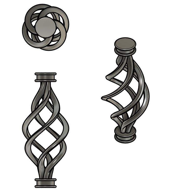
                                                  Here's a challenge…

                                                  basket0.jpg

                                                  #596491
                                                  SillyOldDuffer
                                                  Moderator
                                                    @sillyoldduffer
                                                    Posted by Gary Wooding on 28/04/2022 15:45:12:

                                                    Here's a challenge…

                                                    basket0.jpg

                                                    I'm sure this can be done in FreeCAD, but so far I've failed! The hard part is drawing a line that spirals in 3 dimensions, which the Part Design sketcher doesn't support (I think.) The Drawing workbench does create 3D lines but I can control them. My efforts are worse than a drunken teenage learner driver trying to parallel park for the first time in a car he's never been in before that's towing a caravan.

                                                    The two end pieces are easy, as is generating a pillar by sweeping a sketch along a line. Regrettably, I can't draw a sensible 3D line in FreeCAD to save my life. Anyone else know how?

                                                    Excuses time: I'm deep into learning SolidEdge at the moment, and it's going well. My understanding is still fairly superficial – for example, I don't know if SolidEdge can do Gary's shape at all yet.

                                                    Dave


                                                    Edited By SillyOldDuffer on 30/04/2022 15:45:19

                                                    #596494
                                                    Gary Wooding
                                                    Participant
                                                      @garywooding25363

                                                      It's part of a spindle for some stair bannisters. I did it in Fusion.

                                                    Viewing 25 posts - 76 through 100 (of 113 total)
                                                    • Please log in to reply to this topic. Registering is free and easy using the links on the menu at the top of this page.

                                                    Advert

                                                    Latest Replies

                                                    Viewing 25 topics - 1 through 25 (of 25 total)
                                                    Viewing 25 topics - 1 through 25 (of 25 total)

                                                    View full reply list.

                                                    Advert

                                                    Newsletter Sign-up