3D-CAD Package Shootout – Cotton Reel Example

Advert

3D-CAD Package Shootout – Cotton Reel Example

Home Forums CAD – Technical drawing & design 3D-CAD Package Shootout – Cotton Reel Example

Viewing 25 posts - 26 through 50 (of 113 total)
  • Author
    Posts
  • #594093
    David-Clark 1
    Participant
      @david-clark1

      Very interesting, watching.

      Advert
      #594104
      Alan Wood 4
      Participant
        @alanwood4

        A version in Fusion 360

        Cotton Reel

        #594108
        blowlamp
        Participant
          @blowlamp

          Another variation in MoI – sorry for dawdling part-way through, I had a slight distraction. blush

          Martin.

          #594110
          Nick Wheeler
          Participant
            @nickwheeler

            Pat's comments are the ones that really matter here.

            Making the body from 3 separate extruded cylinders looks simple but it doesn't make for a particularly good part, and is not easily editable if you need to change any dimensions. The same applies to creating the bore separately. And it's all so slow.

            I used a single solid revolve originally, but the gaps had to be cut out using a more complicated sketch. The single spoke in an existing hole then patterned as a feature is easier to draw, easier to understand and all attributes can be changed simply. A major reason for using CAD is not having to do the calculations to decide on the angles or lengths of lines before drawing them.

            Name the sketches and operations as you do them, because it's hard enough remembering what did what later in the day. You'll have no chance in six months when you want to make the part out of different material.

            #594122
            PatJ
            Participant
              @patj87806

              One example of using references is for a steam cylinder with flanges on it.

              The first cylinder I 3D modeled went well enough, and then I decided I needed to make it longer, and so I edited the length. The flanges were not referenced from the ends of the cylinders, and so the flanges got larger, instead of remaining the same thickness.

              I use revolve quite a bit, but I am not sure how well it stretches, or what that does to the references.

              As I have gotten into some more comlex modeling, I often have to make up techniques as I go, and sometimes that works, and sometimes it does not.

              Remembering what I did 40 steps back can be rather trying, although one can generally poke around and figure it out. What I do now for comlex parts is to hit the "print-screen" button after each step, and past that into a photoshop program.

              Then all I have to do is flip back through the screen captures, and I can seen exactly what I did, even a year or more later, and very quickly figure it out.

              But getting back to the basic question of the thread, if you can trade of some stability for cost, then there are some good inexpensive packages out there. I think all of the 3D packaged have improved over time.

              I should note that I looked at one rather expensive 3D package, and then read the reviews, and professional users said it had stability issues, so this can occur across all price ranges.  Do your homework.

              If you can't afford to have a part lock up in mid modeling, such as with a complex work project with a tight deadline, then you spend more money on a more stable product, since that is actually the cheapest route in a work project situation.

              And Solidworks has a large number of features that I never use.

              I do use motion studies to run steam engines virtually, and this is very helpful since if your model is not exactly correct, the program knows, and the engine will not run in simulation (which is very frustrating, so I test one part at a time, to keep track of which part makes it all stop running).

              SW has some molding features, and since I do foundry work, this sometimes is handy.

              I can make a model, draw a cube around it, and then create a mold cavity, such as would be used for a corebox, and then 3D print a corebox.

              Generally speaking though, I use just a handful of tools over and over again, such as extrude boss, rotate boss, extrude cut, revolve cut, fillet, and draft angle since I 3D print patterns.

              I would guess that 95% of my work uses the above commands only.

              It took me a while to figure out how to add planes where needed them, and rotate those planes.

              Once I figured that out, life was much easier.

              .

              Edited By PatJ on 12/04/2022 12:07:02

              Edited By PatJ on 12/04/2022 12:09:16

              #594126
              HOWARDT
              Participant
                @howardt

                I used AutoCad as 2D then Inventor for 3D, quickly got in the habit with Inventor of creating parts as they would be made ie starting with a basic block or round. Doing it this way I was sure that the part could be machined. When I started as a self employed contractor with firms that had just took up Inventor I saw many occasions when some feature were just impossible to produce. Whilst my approach may not have used the minimum of key strokes I could still edit it at the end.

                #594129
                SillyOldDuffer
                Moderator
                  @sillyoldduffer
                  Posted by JasonB on 12/04/2022 07:20:32:

                  … Interesting that of all the various reels posted Dave's all look the least like the photo he first posted so who if firing blanks? Can't be three programs that can't get the spokes right can it?smile p

                  I hadn't intended anyone to do the spokes, thinking it was a useful next step. Gold star to all those who added them, though it's very naughty they copied the photograph rather than the drawing! The boss will be furious when she finds out: the reels are to be milled from stainless steel blanks, and machining sharp corners will push the price up!

                  freecadsharpspokes.jpg

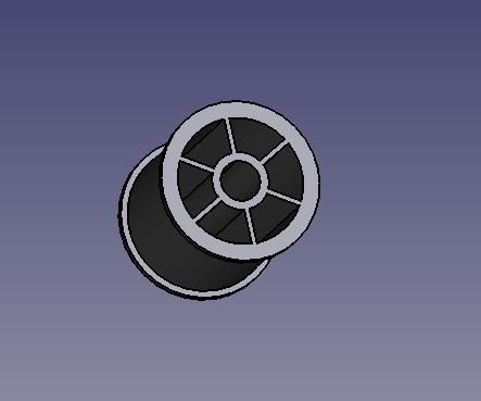
                  Good point about the importance of the operator. CAD doesn't have a magic button for drawing cotton reels and there are a number of strategies by which they can be modelled. We haven't seen them all yet! Some get a quick result whilst storing up trouble if a fundamental changes later. For example, starting with a sketch that models the spokes first creates a structure less resilient to change than one that cuts the spokes much later. Will the model break if the customer suddenly announces the reel's diameter should be bigger or smaller?

                  Dave

                  #594133
                  blowlamp
                  Participant
                    @blowlamp

                    How about a quick computer mouse in MoI? wink

                    Martin.

                    #594136
                    IanT
                    Participant
                      @iant
                      Posted by SillyOldDuffer on 12/04/2022 13:07:31:

                      For example, starting with a sketch that models the spokes first creates a structure less resilient to change than one that cuts the spokes much later. Will the model break if the customer suddenly announces the reel's diameter should be bigger or smaller?

                      Dave

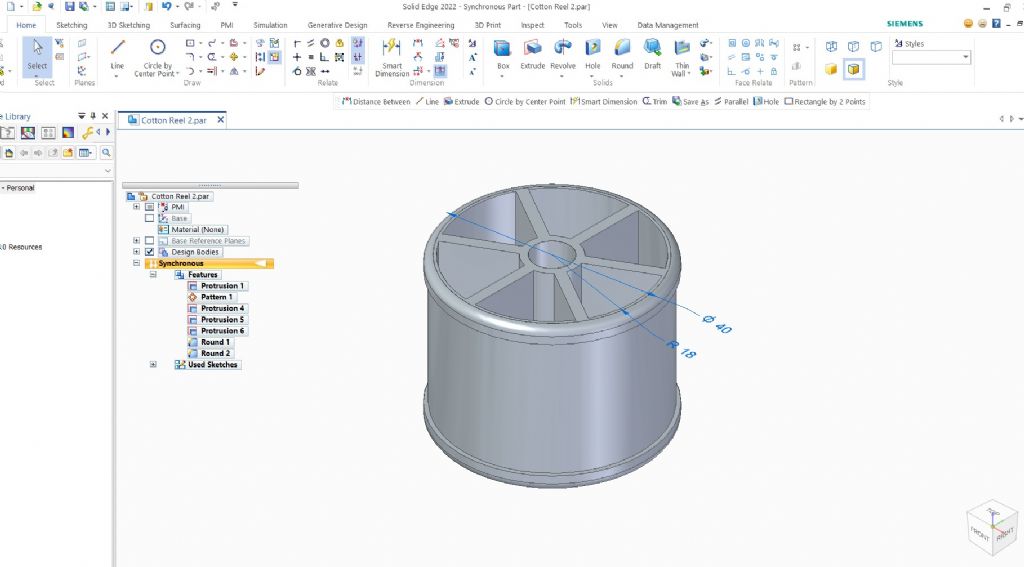
                      Let's see what happens in Solid Edge Dave….taking my existing Cotton Reel model…

                      Used smart dimension to select the outside reel diameter and change it to 40mm (from 30mm). I can do this because it is not a dependent dimension.

                      cotton reel - change outside diameter.jpg

                      So then do the same for the internal diameter… (radius from 12.25 to 18mm)

                      cotton reel - change internal diameter.jpg

                      Spokes still look OK. Might not have been as predictable if I'd tried to increase the internal diameter to exceed the external one first though. To be clear, I've only changed the two diameters here – nothing else was altered.

                      Regards,

                      IanT

                      #594161
                      David Jupp
                      Participant
                        @davidjupp51506

                        As others have pointed out, a 'quick and dirty' one off use model may be done a little differently to a model that will have the key dimensions re-set multiple times to produce variations on a theme (without throwing errors, or disrupting the topology).

                        Both have their place – there is no single 'correct' answer.

                        #594178
                        duncan webster 1
                        Participant
                          @duncanwebster1

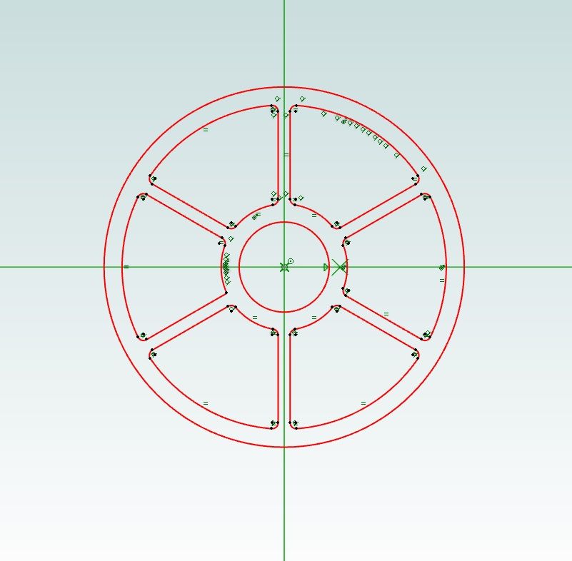
                          My poor attempt, just noticed I've only done 4 spokes. Solid edge, draw half the outer profile on one face, revolve it, draw the Sector holes and centre hole on the top face, cut extrude.

                          I've used SE 2D before (quite a while back), but never the 3D. It wil take some getting used to but there are a lot of features to say the least.

                          bobbin.jpg

                          #594191
                          PatJ
                          Participant
                            @patj87806

                            I think an interesting comparison would be to see which program(s) easily allow the modification of the various types of generated shapes, such as the spindle.

                            I have not kept track of such things, but I have noticed it from time to time, that I can't edit some shapes as easily as others.

                            I am not sure if this is due to limitations of Solidworks, or whether it is inherit in the way all 3D modeling programs work.

                            I have had situations where I extrude some shape, and it all works fine for a while, and then I have to add a few more shapes or cuts, and the whole thing gets balled up, to the point where I basically have to start over with a completely new approach.  Sort of like what I imagine a game of chess would be like (I don't play chess, but I can imagine).  Things tend to cascade, sometimes with very bad results.

                            Occasionally I can drag a feature up or down one or more levels, but this rarely works.

                            The places on the feature tree can be critical.

                            No two objects are exactly the same, and things like draft angle and tapered support legs can really throw some wrenches into the gears.  Compound curves can also be challenging for the best of 3D programs.

                            I definitely learn something new every day in 3D modeling, and have learned quite a bit already from this thread.

                            Discussion is definitely a good thing.

                            Sometimes I use a hybrid of all the methods shown.

                            3D modeling definitely forces creative thinging.

                            .


                            Edited By PatJ on 13/04/2022 00:49:15

                            #594193
                            PatJ
                            Participant
                              @patj87806

                              LOL, that would be "thinking".

                              Speed typing has its disadvantages.

                              But as I mentioned about chess, the first few moves can be critical, and may determine the win/loss outcome.

                              .

                              #594211
                              John Hinkley
                              Participant
                                @johnhinkley26699

                                Seeing as how the world and his dog are taking up the challenge, I might as well weigh in with my effort.

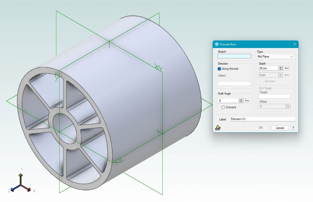
                                First, draw the cross-section of the main body, then extrude to 28mm

                                mid section sketch   extrude to 28mm

                                (I had to take some artistic licence with the diameter of the body as I couldn't see a dimension given)

                                Next, add the end "flange" by duplicating the original cross section and increasing the outside diameter before extruding it 1.5mm.

                                add a flange

                                Mirror it onto the other end about the central plane, add a bit of filleting bling and render it without the joins:

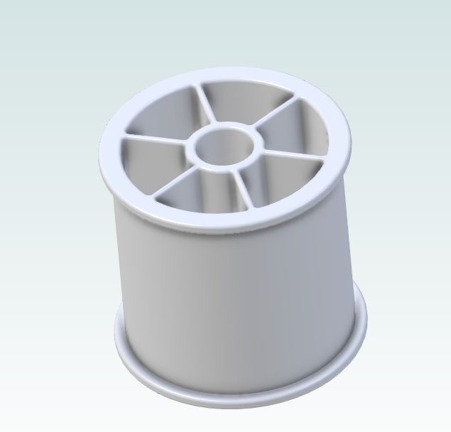
                                cotton reel

                                John

                                Now I'm off to contemplate how many ways I can think of to kill a cat!

                                Edited to include facetious comment!

                                Edited By John Hinkley on 13/04/2022 10:04:13

                                #594212
                                SillyOldDuffer
                                Moderator
                                  @sillyoldduffer

                                  Posted by PatJ on 13/04/2022 00:42:10:

                                  I definitely learn something new every day in 3D modeling, and have learned quite a bit already from this thread.

                                  Discussion is definitely a good thing.

                                  Sometimes I use a hybrid of all the methods shown.

                                  3D modeling definitely forces creative thinging.

                                  .

                                  'Creative thinging' is a pretty accurate description of my interest in Model Engineering!

                                  I've learned from this thread too, and one factor is the different ways people approach solving the same problem. Even when modelling an object as simple as a cotton-reel! The difference between liking and hating a package might be how slickly the software caters for our individual mind-set, which we might not realise is ill-adapted to the problem. Learning is difficult!

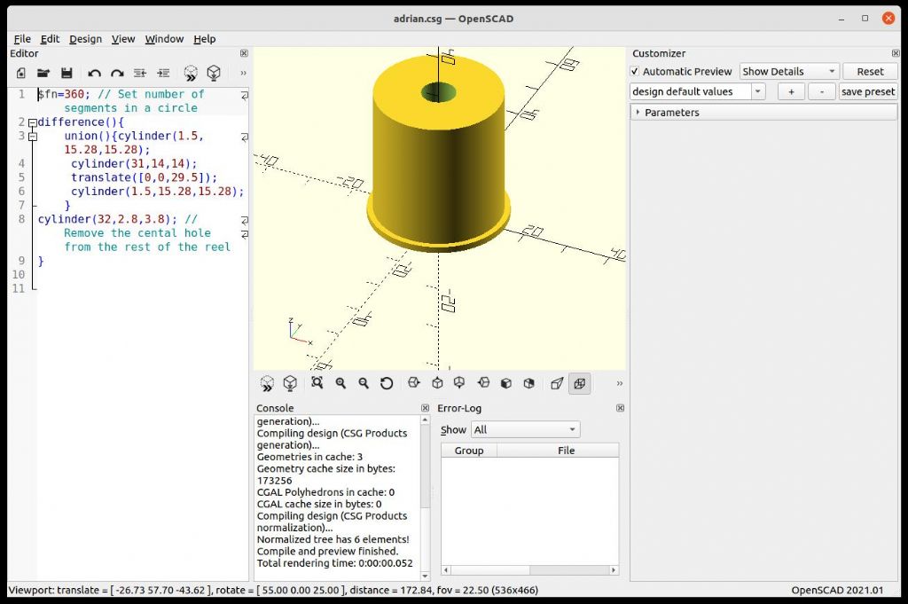
                                  So far all the packages have survived the shootout: they all do the job! I think only one has shown a clear reason why some people should avoid it. OpenSCAD models are built with mathematical scripts, which is a powerful technique, but a particular type of intelligence and skills are needed: maths and programming!

                                  openscad.jpg

                                  Adrian gets First Prize for the most direct answer, but the 'Programmers Solid 3D CAD Modeller' is a steep learning curve if you don't know a bit about set theory, coordinate systems, programming, and the language. Adrian's OpenSCAD solution:

                                  $fn=360; // Set number of segments in a circle
                                  difference(){
                                  union(){cylinder(1.5,15.28,15.28); cylinder(31,14,14); translate([0,0,29.5]) cylinder(1.5,15.28,15.28);}
                                  cylinder(32,2.8,3.8); // Remove the cental hole from the rest of the reel
                                  }

                                  Although there are compelling reasons for modelling by writing code, I don't think they apply to the majority of mechanical engineers, especially hobbyists. Most of us, I think, are happier clicking buttons with a mouse. Programming is difficult. By the by, Adrian's cotton-reel in the picture above is missing its top: my fault – as an officious ex-C programmer, I added an extra semi-colon, which changed what the code does. Oops!

                                  Dave

                                  #594213
                                  IanT
                                  Participant
                                    @iant
                                    Posted by PatJ on 13/04/2022 00:42:10:

                                    I think an interesting comparison would be to see which program(s) easily allow the modification of the various types of generated shapes, such as the spindle.

                                    I have not kept track of such things, but I have noticed it from time to time, that I can't edit some shapes as easily as others.

                                    I am not sure if this is due to limitations of Solidworks, or whether it is inherit in the way all 3D modeling programs work.

                                    I know very little about other CAD systems Pat – but my understanding is that most use what is called "Ordered" mode – that is one based upon a build history. Solid Edge offers both "Ordered" and "Synchronous" modes and you can switch between them if required. Normally you set a default design mode and I decided from the outset to (learn to) use synchronous mode, as it seems to be preferable in general use.

                                    More experienced CAD users (coming from other 3D systems) may find ordered mode more familiar. In terms of my general design work though, synchronous seems to be the better choice. This may be a feature unique to Solid Edge but I don't really know.

                                    This short video explains the differences between the two modes better than I can.

                                    (2) Synchronous vs Ordered Modes in Solid Edge – YouTube

                                    Regards,

                                    IanT

                                    #594226
                                    Neil Wyatt
                                    Moderator
                                      @neilwyatt

                                      The modern way is to scan a cotton reel…

                                      Neil

                                      #594239
                                      SillyOldDuffer
                                      Moderator
                                        @sillyoldduffer
                                        Posted by Neil Wyatt on 13/04/2022 11:00:39:

                                        The modern way is to scan a cotton reel…

                                        Neil

                                        In this thread you have to explain how you did it Neil!

                                        Quite a good description of how to scan a human sized object with 40 raspberrypi computers fitted with cheapo camera modules here. The computers/cameras are mounted 3 to a pole, and the subject, a reluctant child, is surrounded by poles. The computers are networked, and their cameras can be synchronised to analyse the images with a bigger computer.

                                        Not the only way of doing a 3D scan. Wish I had more time and energy!

                                        Dave

                                        #594273
                                        John McNamara
                                        Participant
                                          @johnmcnamara74883

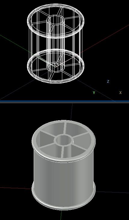
                                          Cotton reel drawn with plain Autocad
                                          About 7 minutes work I am getting a bit out of practice.

                                          cotton reel.jpg

                                          #594278
                                          Martin King 2
                                          Participant
                                            @martinking2

                                            Neil,

                                            A long while back I worked on a film with Ridley Scott directing using 150 Canon SLR cameras and a 4 Tonne motion control rig to do a time slice segment for an industrial company promo.

                                            Really hard to get your head round even when you know what is going on!

                                            Working out the playback frame rate was a nightmare, fortunately a 20yr old whiz kid was on hand to tell me the numbers!

                                            Cheers,Martin

                                            #594287
                                            SillyOldDuffer
                                            Moderator
                                              @sillyoldduffer

                                              Having modelled a cotton-reel with one's preferred package the next stage is to make a real one. With a 3D-printer this is usually easy. Sometimes the technology is built in, otherwise the CAD package should be able to export a suitable file. In FreeCAD, select File->Export, select the file type to 'STL Mesh' and press the Save button.

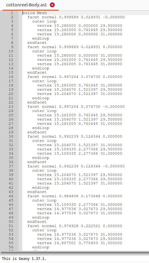
                                              STL describes the model's outer surfaces as a mesh of triangular facets, this being a format that can be understood by a gcode generator.

                                              The text representation of my cotton reel's STL file runs to 21000 lines: takes the computer a blink to write it, you wouldn't want to type it in by hand! A vertex is a corner, so the file contains thousands of x,y,z coordinates in millimeters. Starts like this:

                                              cottonreel.jpg

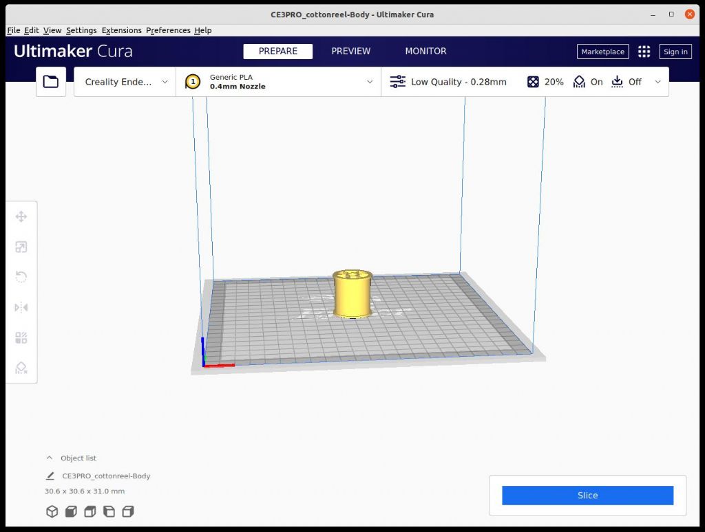
                                              Mildly interesting, but fortunately not necessary to understand STL. I use Cura to slice it into the gcode understood by my Creality Ender printer. Cura just opens the file, the printer is already identified, so press the slice button.

                                              curacottonreel.jpg

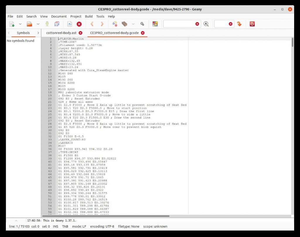
                                              'Slice' generates gcode which is copied to a memory card, and plugged into the printer. The gcode starts:

                                              cotton-reel-gcode.jpg

                                              Another typing job best avoided because the cotton-reel requires 75102 lines of gcode. Unusually big by my standards, probably because of the intricate extruder movements needed to squirt the spokes.

                                              With the memory card in the printer, and the right file selected, the printer can be left to get on with it.

                                              dsc06587.jpg

                                              And about 25 minutes later:

                                              dsc06588.jpg

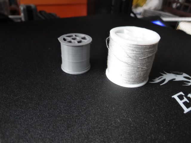
                                              Here it is, next to the original:

                                              dsc06589.jpg

                                              Shock horror, the cotton-reel is too small – has the Silly Old Duffer blundered again? Not this time. As this is a demo I told Cura to reduce the reel's size by 75% to save time and plastic filament. A 75% scale reduction saves about two thirds of the print time and material. When prototyping there's often no need to print parts full-size. For the same reason, Cura is set to print in low-quality and low-density: it can make nicer cotton-reels than the one in the photo, just takes an age to do it. Can't expect too much of a hobby printer costing less than £200.

                                              Dave

                                              Edited By SillyOldDuffer on 13/04/2022 18:43:51

                                              #594613
                                              duncan webster 1
                                              Participant
                                                @duncanwebster1

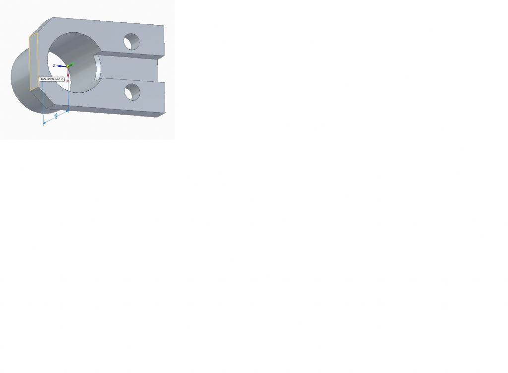
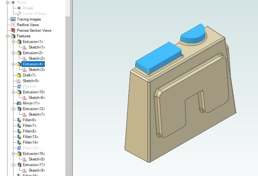
                                                It's not a cotton reel, but I'm stuck, looking for a guru. This is a guard to stop some fiddly little wires getting knocked about. Drawn in SE community edition. I cant remember quite how I created the hole through, but I should have had it blind at the far end. I've spent ages, unsuccessfully. Anyone got any guidance? I think I might have created the hole by having a circle in the ZX plane and extruding it both ways, but that's a guess really. It's taken me longer to get to here than to actually make it, but I've chopped up lumps of ally before, this is new stuff, to me at least

                                                guard.jpg

                                                #594616
                                                IanT
                                                Participant
                                                  @iant

                                                  Hi Duncan,

                                                  If I understand your problem correctly, then set your working plane at the end (on the face) you want to infill, draw/sketch your new infill section and extrude it to the depth required. I'm assuming you are using synchronous mode but it may work in ordered too (not sure, as I don't generally use it myself)

                                                  Regards,

                                                  IanT

                                                  #594621
                                                  duncan webster 1
                                                  Participant
                                                    @duncanwebster1

                                                    Yes I'm in synchronous, and YES IT WORKED, thanks a million. Expect lots more queries, unfortunately I'll have forgotten by tomorrow, general antiquity you know

                                                    #594629
                                                    JasonB
                                                    Moderator
                                                      @jasonb

                                                      Duncan, not sure how SE does it but most packages give a list of each operation used to create a part. In Alibre if i run the mouse over the list each item on the model will be highlighted as I go down the list so you can see what you did and then edit the particular item.

                                                      list.jpg

                                                    Viewing 25 posts - 26 through 50 (of 113 total)
                                                    • Please log in to reply to this topic. Registering is free and easy using the links on the menu at the top of this page.

                                                    Advert

                                                    Latest Replies

                                                    Viewing 25 topics - 1 through 25 (of 25 total)
                                                    Viewing 25 topics - 1 through 25 (of 25 total)

                                                    View full reply list.

                                                    Advert

                                                    Newsletter Sign-up