Was just about to start re-assembling everything when I noticed there was a couple of parts I hadn't sorted. There is a capped tube next to exhaust outlet on the each steam chest which I believe to be a manual oiler point (did raise a thread on the forum to see if anyone had any other ideas, but nothing conclusive in the end).

There was only one of these and it was pretty bent and knackered, so a 2nd needed to be made anyway. Back when I first disassembled everything I measured the original and determined it to be 1/8" BSP (28 tpi), I had some Taps & die so went ahead and started to make one only to find that it didn't fit the casting. After some head scratching I re-measured the OD of the pipe at 0.383" which according to the Zeus data book was correct for 1/8" BSP. As a last resort got the thread gauge out and yes it wasn't standard 28tpi but 26tpi!
As I could still use the taps and dies I had for the top end of the pipes & cap, the end that screwed into the casting will have to be cut on the lathe. (I know Tracy tools stock 26tpi Whitform T & Ds but seemed unnecessary cost for one off's) anyway, will be an interesting exercise to lathe cut such fine shallow threads.
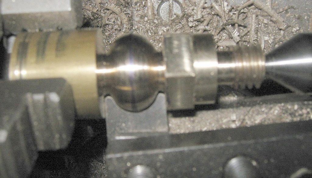
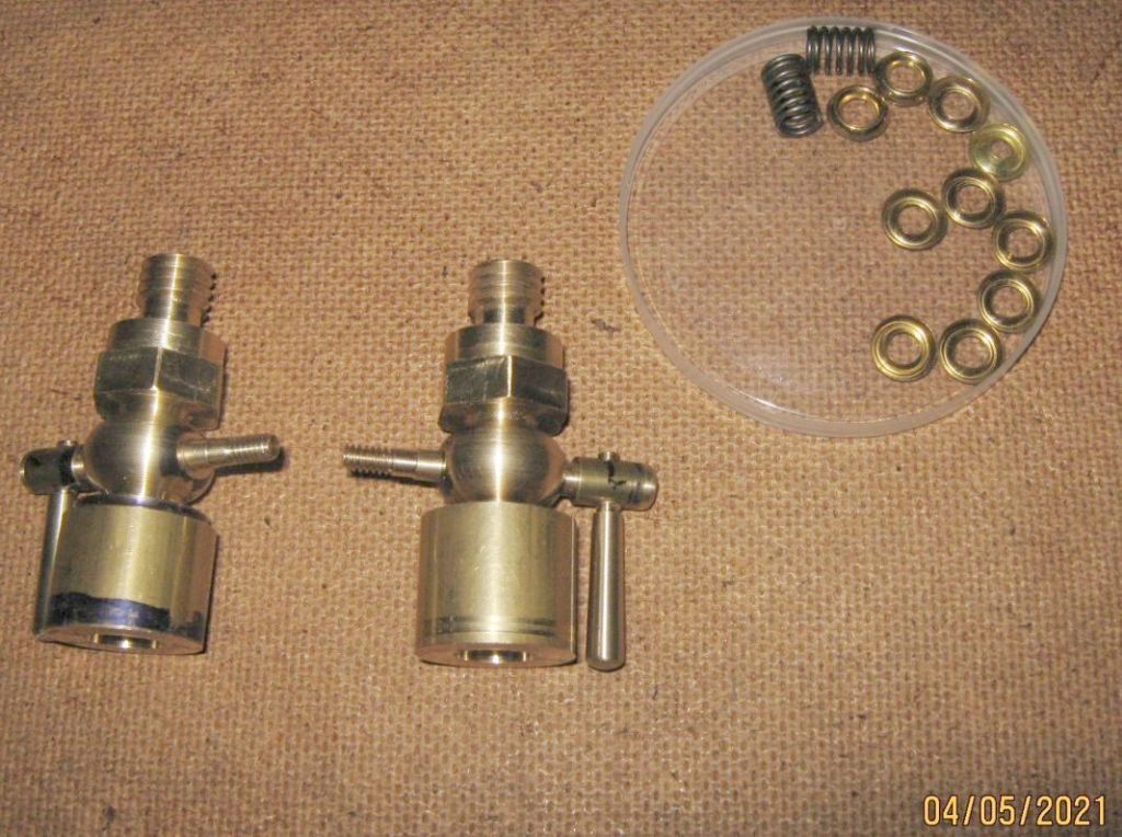
Cylinder manual oilers – as mentioned earlier, decided on making replacement manual cylinder oilers in brass. These actually proved quite a challenge having no design to hand, just working from the model photo (as shown in earlier posting). The initial drawing ended up being modified 'on-the-fly' many times as is often the case with bespoke parts, but worked out OK in the end. One of the challenges was to turn an enclosed 'ball' section in the middle of the unit (this being the part of the body where the tapered valve shaft fits. Unsure of the best approach, so I raised a thread on the website and following several useful suggestions I made a form tool which worked well.

A useful exercise that included lathe threading, 'ball' turning as noted earlier, milling a hex section for tightening the unit into the cylinder, cutting a tapered valve assembly etc
 .
.

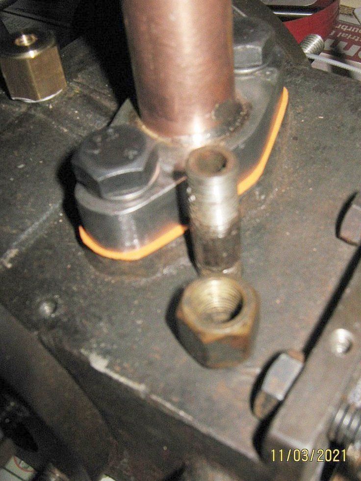
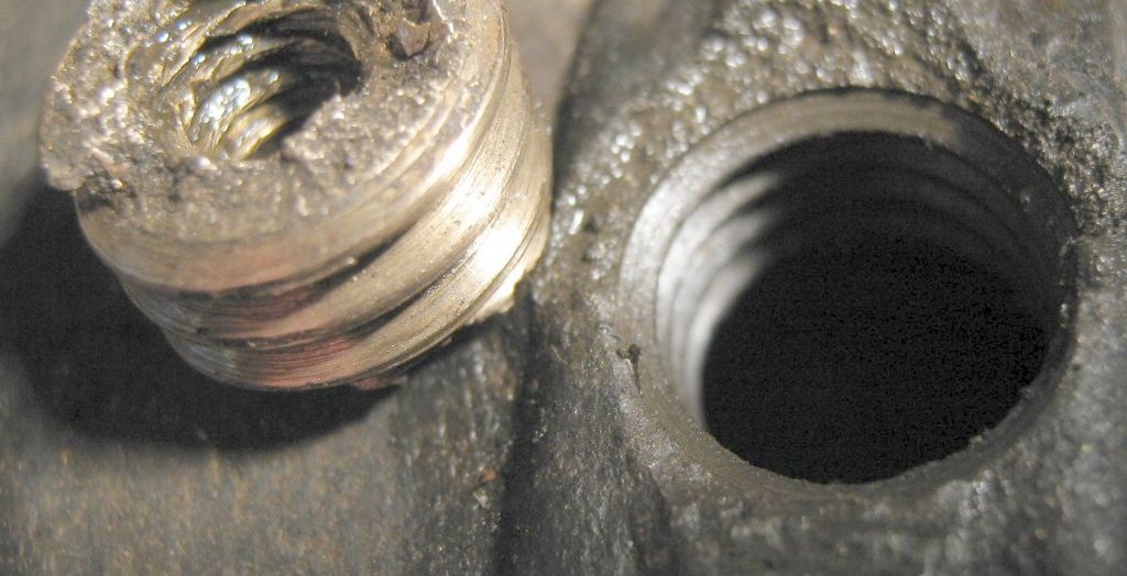
I also realised that where the original oilers had been broken off the cylinders, part of the boss they would locate onto was uneven. Fortunately, neither had resulted in cracks in the cylinder casting, just a ragged surface which would make it impossible to seal the new oilers properly onto the cylinders and be steam-tight.

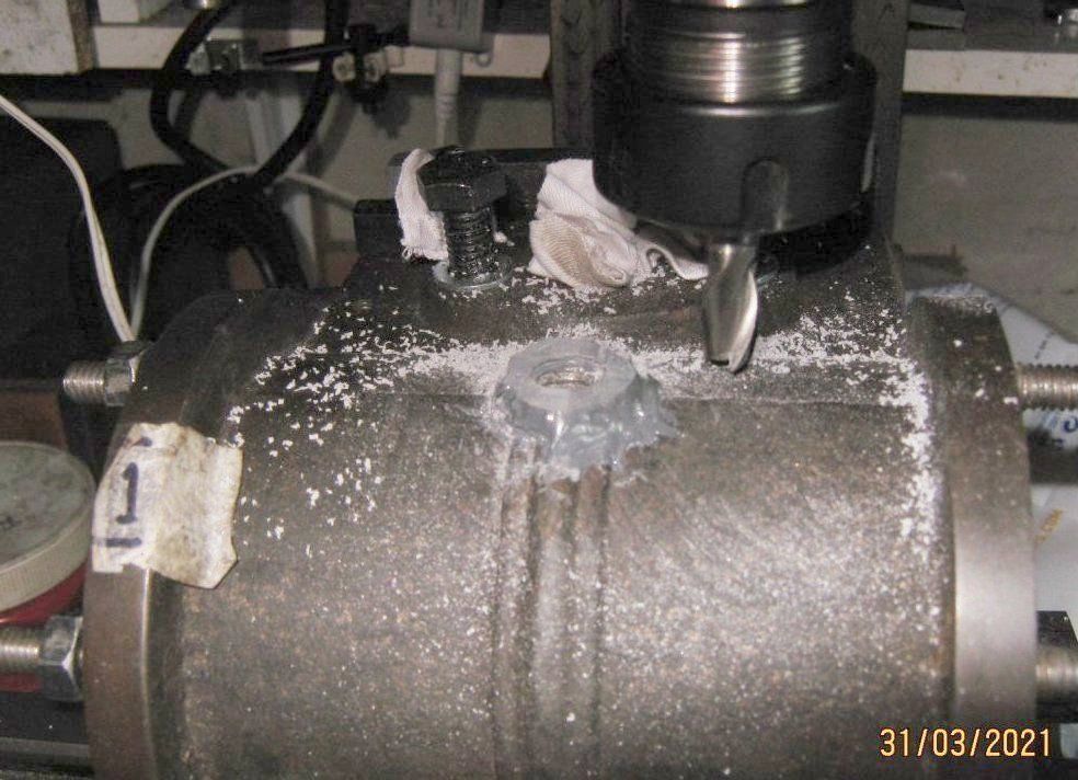
After much deliberation, it was decided to build the bosses up with steel-reinforced epoxy. After on or two attempts this was done. The cylinders were lashed to the mill table with a 1/2" BSW threaded bar in the holes to ensure they were at true verticals, removed these then skimmed the tops to achieve a flat, correctly aligned surface. Worked quite well.

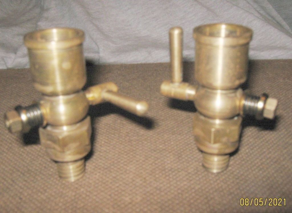
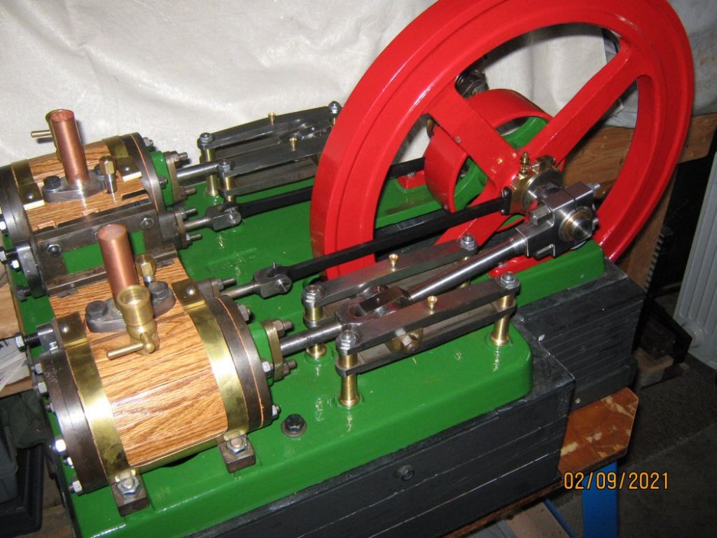
Once the new oilers were completed it was time to start re-building! It was decided to age most of the brass a little, as it was felt (rightly or wrongly) that very bright brass fittings would be out of place on what was originally a working engine as opposed to an exhibition piece.
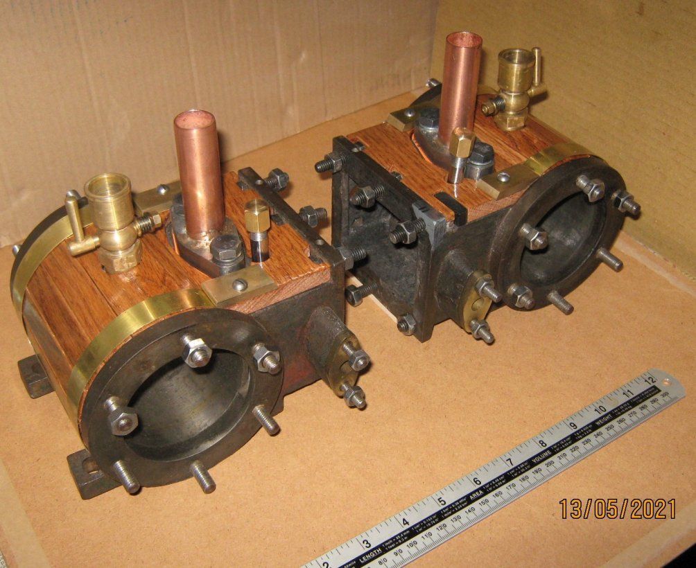
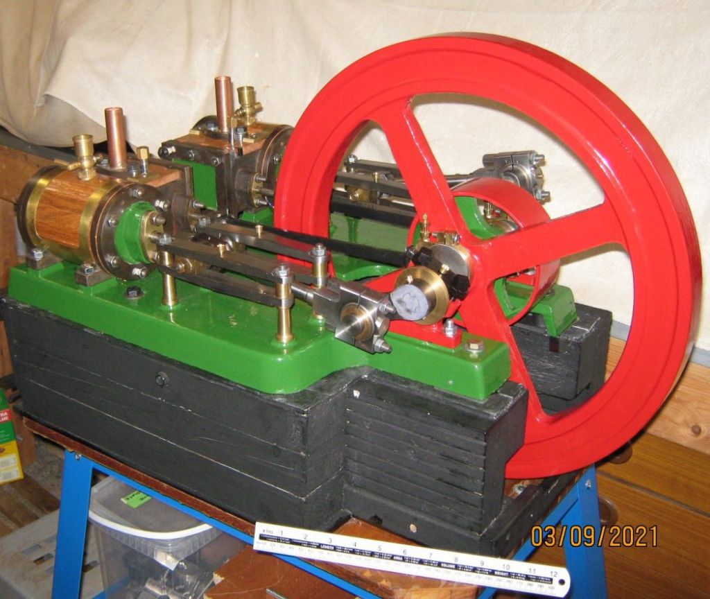
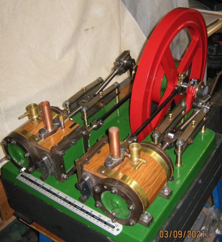
The previously made wooden lagging segments and brass banding were fitted (some adjustment needed here and there as you might expect). The valve chest oiler tubes and cylinder oilers were fitted and much to my surprise everything fitted and nothing got in the way of anything else – amazing!

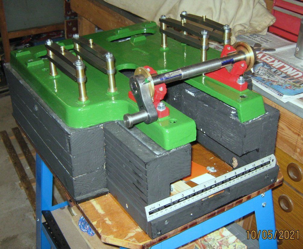
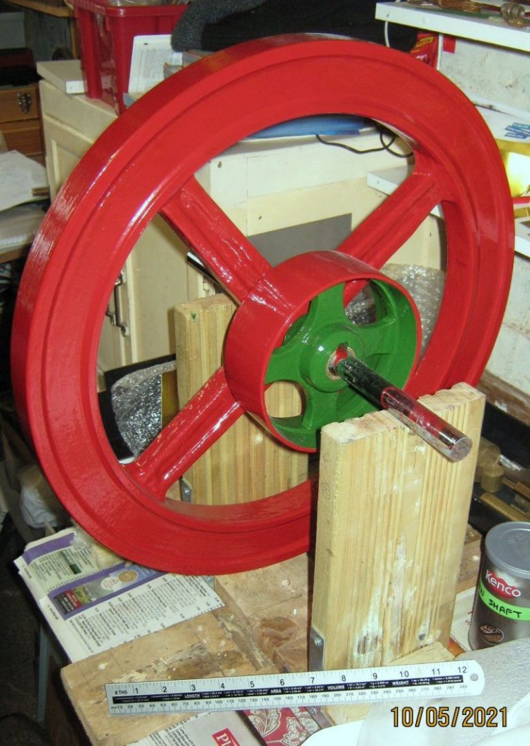
The baseplate assembly , flywheel & pulley had all been cleaned up and re-painted during the winter. These were back to the original colours (though they do look a bit brighter than reality in the pictures) as far as I could tell from the grubby bits of remnant found under the rust.


So the next phase is to start re-assembling everything (for a second time). Will post again when further on, hopefully by then all back together and even possibly ready for a compressed air test (if I can organise any!)
Mike Hurley.


