3 Phase

Advert

3 Phase

Viewing 25 posts - 1 through 25 (of 27 total)
  • Author
    Posts
  • #430918
    Davey J
    Participant
      @daveyj

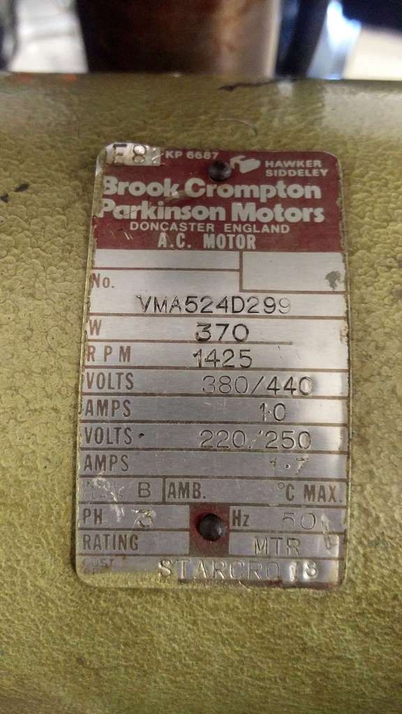
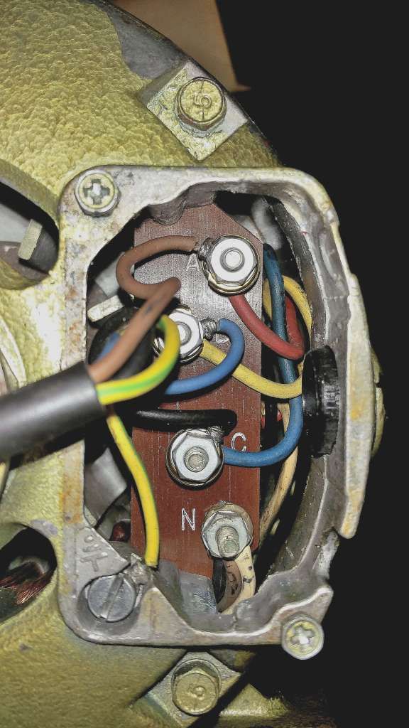
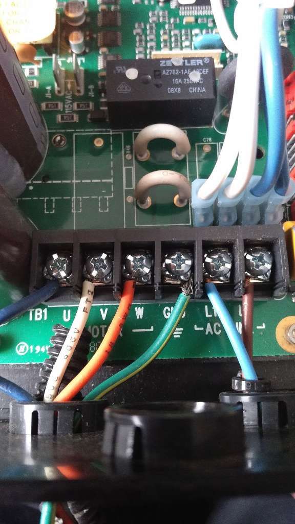
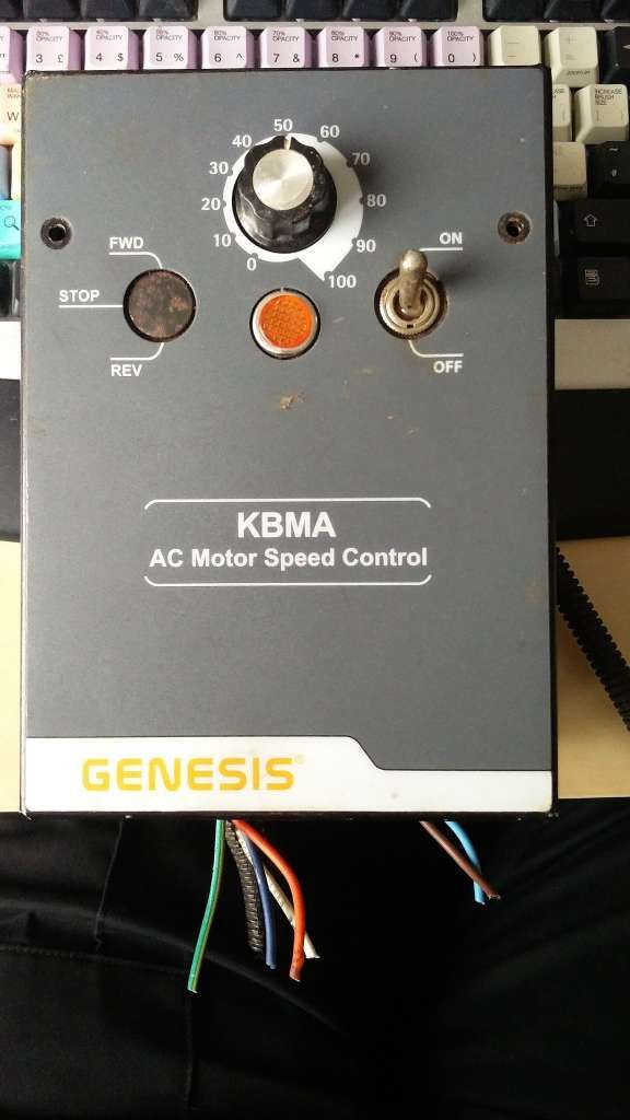
      motor plate.jpgGood evening, first of all I hope this post is in the right place? I have been lucky enough to secure a Startrite pillar drill which is fitted with a three phase motor which the original owner ran on 440v. Knowing nothing of 3 phase I purchased Graham Astbury's book on the subject and am a little confused by what I have read – my fault not the author's! The plate on my motor is as shown which, according to the book, should be a four wire motor as it shows dual voltage on the plate but only three wires and an earth are present and no wire to the neutral inside the motor. Having bought a Transwave unit some time ago which is too big and will have to go back to Fleabay – I though I had better stop and ask for some sensible advice. So is this motor purely 440v or am I able to run it on a 3phase supply outputting 220/250v with three phases? I have also been given one of these as well. Hope this is clear. Many thanks in advancewiring.jpg. David

      Advert
      #33459
      Davey J
      Participant
        @daveyj
        #430922
        old mart
        Participant
          @oldmart

          You need "delta" connections, but the motor is wired "star". I don't know if the wiring can be re arranged, hopefully someone will know. If you bought a new motor it would be easy to change from one to the other, but the mountings and shaft diameter might have changed.

          #430928
          peak4
          Participant
            @peak4

            Yes, you should be able to run it off one of the 240v inverters.

            There is normally a label on the inside of the cover you removed to expose the wiring.
            If it's not there, may I suggest you visit this Mad Modder thread where you will be able to write down the colours of the wires and re-terminate your motor.
            Essentially you take Brown White Black off "N" and double them up on Red Yellow Blue, in that order, leaving the "N" terminal spare.

            Mesh and Delta, are one and the same in this case.

            Bill

            Edited By peak4 on 28/09/2019 21:16:33

            #430929
            Emgee
            Participant
              @emgee

              Davey, looks like the 3 ends of the coils are all connected on the terminal marked N to provide star connection.

              You need to remove these and place in 3 separate connectors so you will have 6 ends in the terminal box, then check for continuity between ends to find the ends of coils.

              If you have 3 coils of almost equal resistance you need to connect them in Delta to allow the use of a 230v VFD.

              Emgee

              #430934
              Davey J
              Participant
                @daveyj

                Bill, Emgee and Old mart many thanks for these replies and in such a short time, this really is an amazing resource of information. I will have a go and see what happens. Thank you for your help it is greatly appreciated and I will persevere with the book! . Davey

                #430940
                old mart
                Participant
                  @oldmart

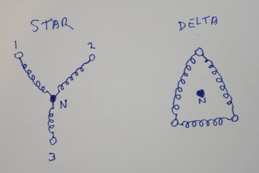
                  What you have got is three phases going into your motor which connect together at the neutral terminal. To change to delta, you have to disconnect the three neutral wires and move them to the appropriate phase connections. The neutral terminal will now have no wires going to it. You need a meter with a low ohms range to find out which wire goes where. My poor diagram shows what it should look like Good luck. Check the connections when the wires are disconnected from the neutral._igp2457.jpg

                  Edited By old mart on 28/09/2019 22:38:02

                  #430956
                  peak4
                  Participant
                    @peak4

                    Old Mart, there's a little bit more to it in that each of the three windings need to be in the correct orientation, but the colours linked to in my earlier post should avoid Davey having any problems.
                    The motor will run rough and overheat otherwise, as one coil will be working against the other two.
                    Bill

                    #430975
                    DC31k
                    Participant
                      @dc31k
                      Posted by peak4 on 29/09/2019 00:31:57:

                      Old Mart, there's a little bit more to it in that each of the three windings need to be in the correct orientation…

                      The motor will run rough and overheat otherwise, as one coil will be working against the other two.

                      Could you kindly describe or post a credible diagram showing how it is possible to put the windings in an incorrect orientation.

                      Reversing the ends of any winding is exactly the same topographically as swapping over two wires of the supply. This is the standard method of making the motor turn in the opposite direction.

                      #430979
                      John Haine
                      Participant
                        @johnhaine32865

                        Topologically.

                        but no, the problem is that there is mutual inductance between the windings, and the couplings between each pair all have to be in the same sense for the motor load to be balanced. This is covered in a couple of threads here.

                        #430980
                        Gray62
                        Participant
                          @gray62

                          Without going into too much motor theory, hope this helps to explain:

                          Reversing a 3 phase motor involves changing the phase rotation, there are only 2 possible phase sequences for a 3 phase system 1-2-3 or 3-2-1, reverse any 2 phases and the motor changes direction.

                          However, reversing 1 winding will not reverse the motor. Each winding is electrically oriented to produce the required N-S magnetic field, as the phase rotate around the connections, so the N-S field in each coil progresses round the stator, effectively ‘pulling’ the rotor with it. Each coil in the stator is not a single winding but several that are interleaved so the stator is magnetically connected at multiple points around its axis. Swapping the orientation of one of these field winding groups essentially puts part of the rotating field into a S-N magnetic orientation in relation to the other windings and will therefore ‘buck’ against the rotation. Invariably this will prevent the rotor spinning and cause excessive heat in the stator windings eventually burning out the stator.

                          #430990
                          john fletcher 1
                          Participant
                            @johnfletcher1

                            Hello David, your motor is connected Star and needed to be re connected Delta to work from your inverter. Have you or a friend a multi meter, as you need one to locate the other end of the three wires at present connected to the terminal N. Assuming that the wires on terminal N to be the number one ends of each of the three winding and the 2 ends to be connected to terminals A,B,&C as shown in your picture.

                            Lift off all the wires from N and with one meter lead connected or touching say A, touch the other lead to one of the three wires previously connected to N. Mark the wire. Do the same to B and C. Now connect A 2 to B one, then B2 to C one, finally C2 to A one. Job done. If the direction of rotation is incorrect SWITCH OFF and exchange a pair of the output wires from the inverter. John

                            #430992
                            Anonymous

                              Must be an old motor. The rating plate certainly implies it's a dual voltage motor, but the connection box isn't what you'd expect. I'll leave it for someone with more knowledge to suggest a wiring arrangement.

                              Incidentally a star connected motor will run just fine off an inverter producing 3-phase at 230V phase to phase. The issue is that the phase currents, and hence torque and power, will be down by a factor of 1.732, aka the square root of three.

                              Andrew

                              #430999
                              Davey J
                              Participant
                                @daveyj

                                Once again very many thanks for all the help offered here, the depth and breadth of knowledge is a wonderful resource. I am going to try and run it from my 3phase 240v as per Andrew@s suggestion, it is a hobby drill after all, whilst I get rid of the Transwave and obtain something more suitable. Thank you all. David

                                #431005
                                bill ellis
                                Participant
                                  @billellis45274

                                  When I wired my mill up to 220v delta I used the following procedure to ensure correct polarity of the windings. I noted the colours/terminal designations which related to each winding on a post it note. I just used a multimeter rather than a zero centre one and watched which way the needle tried to kick.

                                  i) With a multimeter or continuity tester, you can segregate three sets of windings.
                                  ii) Now, assume one set of windings to be, say, winding "U" and also, designate its terminals as assumed "U1 & U2".
                                  iii) Take a 9V Cell; Connect + ve of Battery to the assumed "U1" preferably thro a push-switch and – ve to the assumed "U2".
                                  iv) Connect a zero centred galvanometer, to another set of winding, say winding "V" such that the assumed "V1" is connected to the + ve terminal of the galvanometer and the assumed "V2" to the – ve terminal of the meter.
                                  v) Now, when the switch is pressed, the zero centred galvanometer would deflect in the positive direction, if the assumed "U1, U2, V1 & V2" are correct.
                                  vi) Else, if the deflection is on the negative side in the galvanometer, change your assumptions for either one of the winding (That is may be the assumed U1 can be U2 and the assumed U2 is U1 . Or keep the assumptions for U winding as it is and reverse it for the V winding (that is assumed V1 is V2 and assumed V2 is V1).
                                  vii) Repeat this test for applying voltage to other windings and confirm your terminal assumptions.

                                  The reason the winding polarity is critical is that the windings must have the proper phase to generate a rotating magnetic field to drive the rotor in a given direction. If one of the windings has the wrong polarity then that winding will be trying to rotate the field in the wrong direction. This causes poor motor torque and generates high winding currents.

                                  HTH

                                  Edited By bill ellis on 29/09/2019 10:17:51

                                  #431011
                                  Gary Wooding
                                  Participant
                                    @garywooding25363
                                    Posted by Andrew Johnston on 29/09/2019 09:32:04:

                                    Incidentally a star connected motor will run just fine off an inverter producing 3-phase at 230V phase to phase. The issue is that the phase currents, and hence torque and power, will be down by a factor of 1.732, aka the square root of three.

                                    Andrew

                                    In a star connected motor running with 440v 3-ph, each winding "sees" 220v, which is exactly the same as they see when running with 220v in delta layout. Hence no loss of power.

                                    #431019
                                    Anonymous
                                      Posted by Gary Wooding on 29/09/2019 10:26:44:

                                      Hence no loss of power.

                                      Pay attention there at the back. smile

                                      That's not what I wrote. If you run a motor in star and at a phase to phase voltage of 240V instead of 415V then there will be a loss of power compared to running at 415V. That's why when running from an inverter that gives 240V phase to phase you need to change to delta to avoid the power loss.

                                      Andrew

                                      #431031
                                      peak4
                                      Participant
                                        @peak4

                                        Davey, From your earlier posts, I gather you have a "3 phase 240v supply"
                                        I and others have made the assumption that its a 240v single phase in, 3 phase out inverter.

                                        Is this correct and what model and ratings are displayed? What country do you live in?

                                        I understand that some folks may not want to visit another forum, such as MadModder, buy may I refer you to the website of the contributor to that forum who shows a photo of the wiring plate on a similar motor to that which you own.

                                        I'll not deep link to his photo for copyright reasons, but I'm sure you could print it out at reduced size and stick it inside your motor's cover plate for future reference.
                                        Bill

                                        Edited By peak4 on 29/09/2019 12:11:51

                                        #431040
                                        Michael Briggs
                                        Participant
                                          @michaelbriggs82422

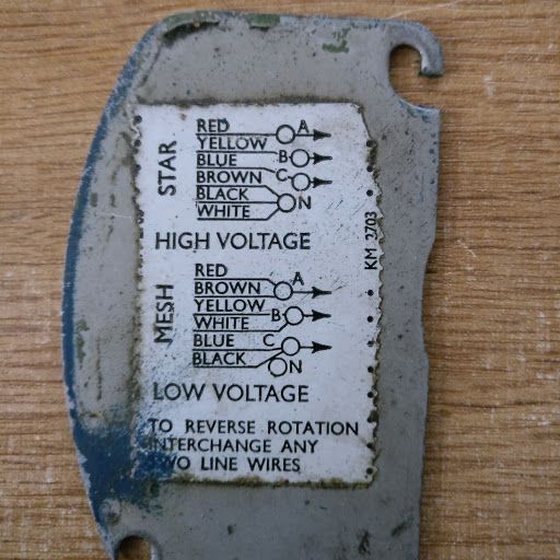
                                          Davey, my Fobco drill has a similar motor, I would have to take the motor off to see the motor plate. The lid of the terminal box shows how to connect for high and low voltages. It is probably the same as your motor :

                                          motor connections.jpg

                                          #431041
                                          Michael Briggs
                                          Participant
                                            @michaelbriggs82422

                                            Sorry, hadn't looked at Bill's link, Michael

                                            #431042
                                            old mart
                                            Participant
                                              @oldmart

                                              From studying the photographs, the colours of the op's wires are the same as the motor plate diagram. This would make it easy to get everything connected correctly.

                                              RED-BROWN

                                              YELLOW-WHITE

                                              BLUE-BLACK

                                              The 3 input wires can be connected any way round, only swapping any two if the motor rotates the wrong way.

                                              #431043
                                              Davey J
                                              Participant
                                                @daveyj

                                                inverter 2.jpgJust looked and my cover plate is the same as "mad-modder's" – just need to know where to look! I have added images of the little inverter I have which is 240v single phase in and 240v 3 phase out it is a KBMA-24D, 24DF 2 for 1/8HP thru 1HP 3-Phase AC Motors rated 208 – 230 VAC, 50* & 60 Hz. Once again thank you all for taking so much time to help it really is appreciated. I will also update my profile which will show I am on the edge of North and West Yorks. Many thanks. Davidinverter.jpg

                                                #431044
                                                Neil Wyatt
                                                Moderator
                                                  @neilwyatt

                                                  If the 'star point' is accessible and it's wired correctly, then the correct wiring for delta sees each of red, yellow and blue connected to one of of the star point wires that doesn't belong to the same coil.

                                                  Your winding connections are the standard colours of red, yellow blue and Brown, white, black so the connections in MIchael Brigg's photo are standard.

                                                  #431049
                                                  peak4
                                                  Participant
                                                    @peak4
                                                    Posted by Michael Briggs on 29/09/2019 13:20:06:

                                                    Sorry, hadn't looked at Bill's link, Michael

                                                    Pleased you did post your photo directly on this forum. I don't like stealing other peoples photos from their web site(s).
                                                    Thanks

                                                    Bill

                                                    #431051
                                                    not done it yet
                                                    Participant
                                                      @notdoneityet

                                                      There is no earth connection to ground on that inverter? surprise

                                                    Viewing 25 posts - 1 through 25 (of 27 total)
                                                    • Please log in to reply to this topic. Registering is free and easy using the links on the menu at the top of this page.

                                                    Advert

                                                    Latest Replies

                                                    Viewing 25 topics - 1 through 25 (of 25 total)
                                                    Viewing 25 topics - 1 through 25 (of 25 total)

                                                    View full reply list.

                                                    Advert

                                                    Newsletter Sign-up