3 HP Frisco Standard Stationary Single 4-Stroke IC Engine

Advert

3 HP Frisco Standard Stationary Single 4-Stroke IC Engine

Home Forums CAD – Technical drawing & design 3 HP Frisco Standard Stationary Single 4-Stroke IC Engine

Viewing 25 posts - 26 through 50 (of 61 total)
  • Author
    Posts
  • #523832
    PatJ
    Participant
      @patj87806

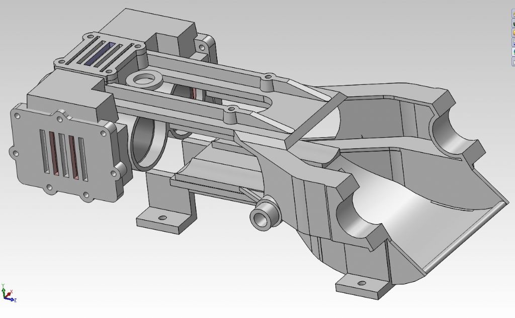
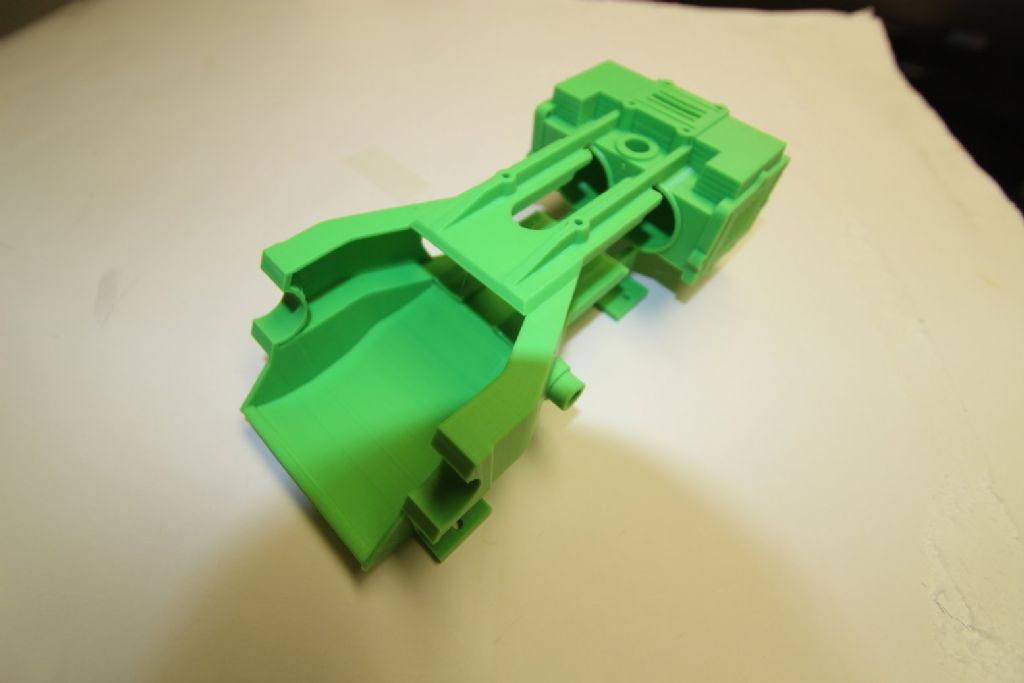
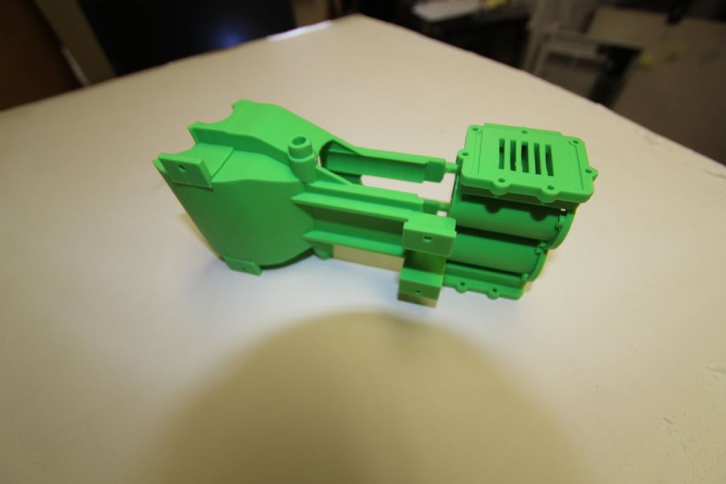
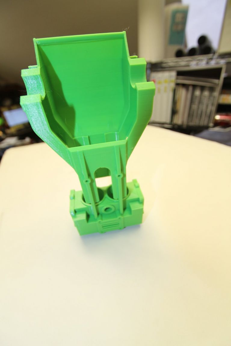
      On a side topic, this is a preliminary (not complete) 3D print and screen image of the 3D model for my Speedy Twin frame/cylinder pattern.

      This would probably be a good candidate for the ceramic shell process, assuming the passages could be worked out somehow.  There are a number of complex steam/exhaust passages that run across the top of this engine.  The core makers for this engine were masters at what they did.

      This was printed on my Prusa.

      Last photo is a full-sized Speedy Twin, for reference.

      This seems to be a very unique engine, with its semi-balanced multi-D valves, and almost instant reversing without using a Stephenson-style link, and only two eccentrics.

      The pressure on the D-valves is reversed when the engine is reversed, but through an extremely clever arrangement, the D-valve does not lift off of its seat when the steam pressure is reversed on it.

      image11.jpg


      rimg_3154.jpg


      rimg_3161.jpg


      rimg_3166.jpg


      img_1923-rev-02.jpg

      Edited By PatJ on 31/01/2021 07:20:46

      Edited By PatJ on 31/01/2021 07:23:54

      Edited By PatJ on 31/01/2021 07:25:59

      Edited By PatJ on 31/01/2021 07:28:02

      Edited By PatJ on 31/01/2021 07:30:07

      Edited By PatJ on 31/01/2021 07:32:18

      Advert
      #523859
      SillyOldDuffer
      Moderator
        @sillyoldduffer
        Posted by PatJ on 31/01/2021 06:56:37:

        This began a discussion on another forum about how it was done in the day, and so I looked at my photos from the Soule Museum in Meridian MS (USA), and there were a great number of gear patterns.

        The question was raised , and I think it is a fair question "Why cast a gear? Why not just cut a blank and then use gear cutters to cut the teeth?".

        My guess is that back in the day, it was far easier to cut gear teeth in wood, and then cast the gear.

        A cast gear would probably only require minor cleanup and cutting to get it the exact size, and so a great deal of machining would be eliminated for every gear produced if a cast gear was used.

        Back in 2012, I wanted to make castings in gray iron, and "they" said "you can't do that in a hobby setting".

        "They" were wrong. Then they said "Well if you do make an iron casting, it will have inclusions, and will have chilled spots that are too hard to machine". "They" were wrong again.

        I'm fascinated by the history of technology too. Gears go back a long time, and the sophistication of the 2000 year old Antikythera Mechanism surprised everybody!

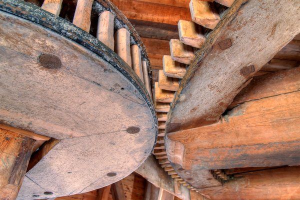
        However, for centuries the main use of gear wheels was in windmills and watermills grinding flour. Millwrights were agricultural, metal expensive, and so the wheels and teeth were both made of wood.

        millgears.jpg

        At first simple round rods, later more accurately shaped teeth. Early gear makers didn't understand the mathematics, but overtime wear tends to shape the teeth more-or-less correctly, and fairly good gears can be made by rule of thumb methods.

        As wooden gears wear quickly and aren't reliably strong, there was obvious advantage in metal, at first just copying wooden methods, but later casting them whole.

        'Fairly good' isn't ideal, and clock-makers were first to develop gears on scientific principles, looking for the optimal curves needed for meshing gear wheels to roll over each other. Clock gear tooth shapes favour low friction rather than power transfer, so industry stuck to traditional methods for many more years. Cast gears made with teeth of nearly the right shape were common. Far from perfect in that they were noisy, inefficient and wore out relatively quickly, but they did the job provided rpm was low. However, as industry demanded more power and speed, cast gears became less popular. By this time, the maths needed for power transfer rolling curves was well understood, so industry moved to gear cutting. Understanding the maths also made it possible to develop special purpose precision gears, opening the door to all sorts of mechanisms. Cut teeth are all correctly curved, the gear is uniformly strong, and the metal is tougher and harder than cast-iron. And accurately shaped teeth wear slowly and are quieter.

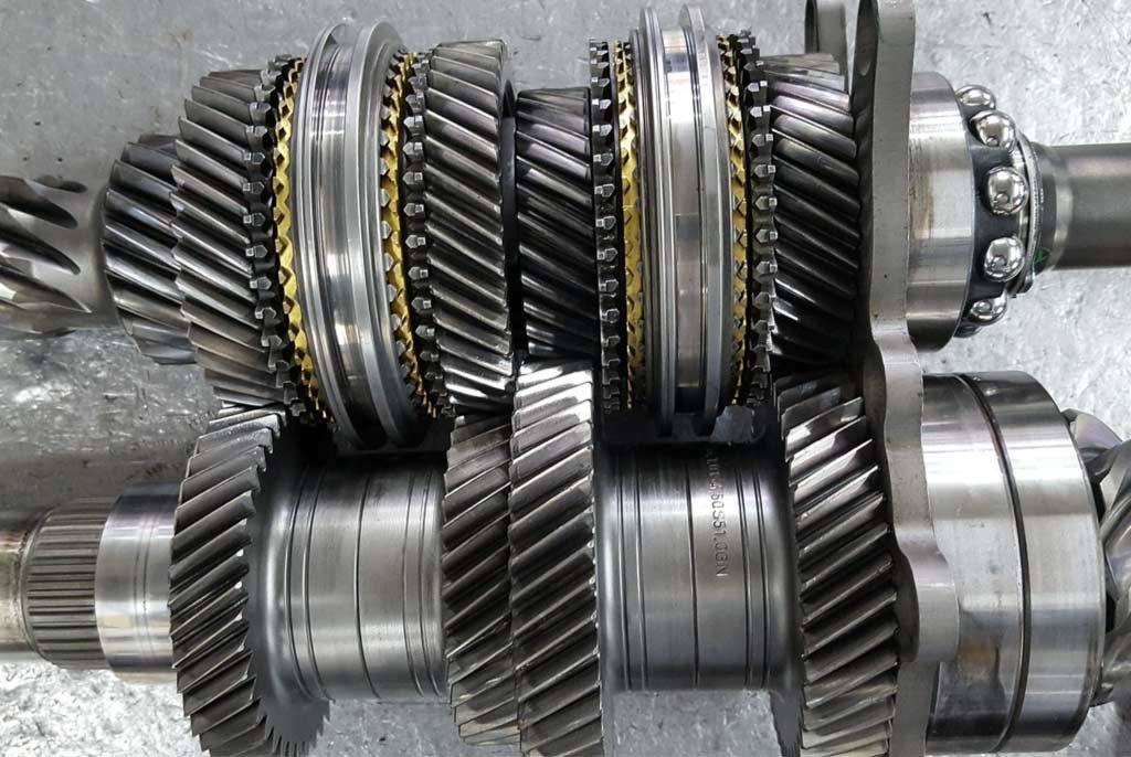
        Quieter, not quiet! When motor cars appeared, the appalling racket made by their gearboxes was a serious problem. No one cared if working people were deafened in factories, but rich people wanted better. This led to a second burst of research that slowly got rid of most of the whine and clatter made by plain gears. Again the answer is precision shapes, no simple cast gears in this gearbox:

        tranmissions-shaft-from-within-a-car-gearbox.jpg

        I don't know if rough toothed gear blanks are ever cast in steel and then finished. It would reduce the amount of cutting, but it might be quicker and more structurally consistent to work with a round blank. Quicker because blanks don't need to be aligned in machines, and consistent because cast teeth aren't quite the same temper as the body. A Production Engineer would understand the trade-offs.

        Excellent work by the way! Impressive mastery of several techniques. Thanks for sharing.

        Dave

        #523861
        Andy_G
        Participant
          @andy_g
          Posted by PatJ on 31/01/2021 06:00:03:

          I am still hazy about the exact angle of the two gear helix.

          If the angle is off slightly, does that mean that the two shafts will not remain synchronized? but instead one shaft will rotate slightly too fast, thus throwing off the engine timing?


          The angles need to add up to exactly 90 degrees (for a right angle drive). If they are 'off' the gears won't mesh correctly with the axes at 90° (think of trying to mesh spur gears with one axis tilted with respect to the other).

          The diameter of each gear depends on the tooth count *and* helix angle for a given *normal* pitch. One is free to choose arbitrary angles (subject to them summing to 90° ) but the diameter of the resulting gears will vary. For the unique set of angles given previously, the gear sizes are identical with a 2:1 ratio.

          Reduction ratio is set by the tooth count (only).

          Edited By Andy_G on 31/01/2021 10:23:35

          #523907
          Andy_G
          Participant
            @andy_g

            After encountering frustrations trying to get Fusion360 to draw a parametric involute, I've found this add-in by Ross Korsky which looks very promising:

            Link

            It also seems to include provision for adding clearance for 3D printed gears, etc.

            Andy

            ______________________________________________________________

            Relevant notes for interest:

            General Usage Instructions

            Once the add-in is running its button can be found under the CREATE menu.

            Description of inputs

            Gear Standards:

            The true involute pitch and involute geometry of a helical gear is in the plane of rotation (Radial System). However, because of the nature of tooth generation with a rack-type hob, a single tool can generate helical gears at all helix angles as well as standard spur gears. However, this means the normal pitch is the common denominator, and usually is taken as a standard value (e.g. 14.5 deg or most commonly 20 deg). In other words if you plan to have your gear manufactured with a standard hob you will likely want to use the "Normal System" and a pressure Angle of 20 degrees.

            Normal System: Pressure angle and module are defined relative to the normal of the tooth (i.e. defined as if the tooth was rotated by the helix angle). When defining a gear in the normal system changes to the Helix Angle will cause the gears diameter to change as well as the working thickness (and therefore the strength) of the tooth.

            Radial System: Pressure angle and module are defined relative to the plane of rotation. When defining a gear in the radial system changes to the Helix Angle does NOT affect the gear diameter but it does change the "normal pressure angle" which may require custom tooling to have the gear manufactured (obviously this is not an issue if 3D printing the part).

            Sunderland: The Sunderland machine is commonly used to make a double helical gear, or herringbone, gear. The radial pressure angle and helix angle are fixed at 20° and 22.5°, respectively. The tooth profile of Sunderland gears is also slightly shorter (and therefore stronger) than equivalent gears defined in the radial system.

            Handedness: Direction the tooth appears to lean when placed flat on a table.

            Helical gears of opposite hand operate on parallel shafts.

            Helical gears of the same hand operate at right angles.

            Helix Angle: Angle of tooth twist. 0 degrees produces a standard spur gear. The higher the helix angle the more twist the gear has.

            Pressure Angle: The pressure angle defines the angle of the line of action which is a common tangent between the two base circles of a pair of gears. The short of it is this: leave this value at 20 degrees until you have reason to do otherwise – but know that any pair of gears MUST have the same pressure angle.

            Module: The module is the length of pitch diameter per tooth. Therefore m = d / z; where m is module, d is the pitch diameter of the gear, and z is the number of teeth.

            Teeth: Number of teeth the gear has. The higher the helix angle, and to some extent pressure angle, are the fewer teeth the gear needs to have to avoid undercutting. It is possible to create a Helical gear with a single tooth given a high enough Helix Angle. CAUTION: due to performance reasons, do not make gears with several hundred teeth.

            Backlash: [experimental] a positive value here causes each tooth to be slightly narrower than the ideal tooth. In the real world having a perfect tooth is not often desired, it is better to build in a little backlash to reduce friction, allowing room for lubricant between teeth, and to prevent jamming. Backlash is allowed to also be negative which has no real world application I'm aware of but may be useful for compensating for undersized teeth which were 3D printed, etc.]

            #524189
            PatJ
            Participant
              @patj87806

              Dave-

              Thanks much for the kind works and the interesting information.

              That Antikythera mechanism was quite the piece of work. I am not convinced we know more than the ancients knew. And it makes you wonder what they knew and how far back they knew it before they created this mechanism.

              Very humbling indeed as I struggle (unsuccessfully so far) to try and create two gears with a $1,000 computer and expensive 3D software, LOL.


              Andy G-

              Thanks for the gear information.

              I keep reading about helical gears over and over, so that the terms can begin to sink in.

              I must say I am helical-gear-challenged for sure, but I have not thrown in the towel just yet.


              I tried JasonB's method, and the first gear went pretty well.

              The second gear did not go well.

              Solidworks seems a bit quirky with the "swept cut" command, and the typical options that I am use to on many other commands is not present on the swept cut command, such as extract from midplane, and the ability to use either positive or negative angles.

              I will rest a bit and then try another approach.

              .

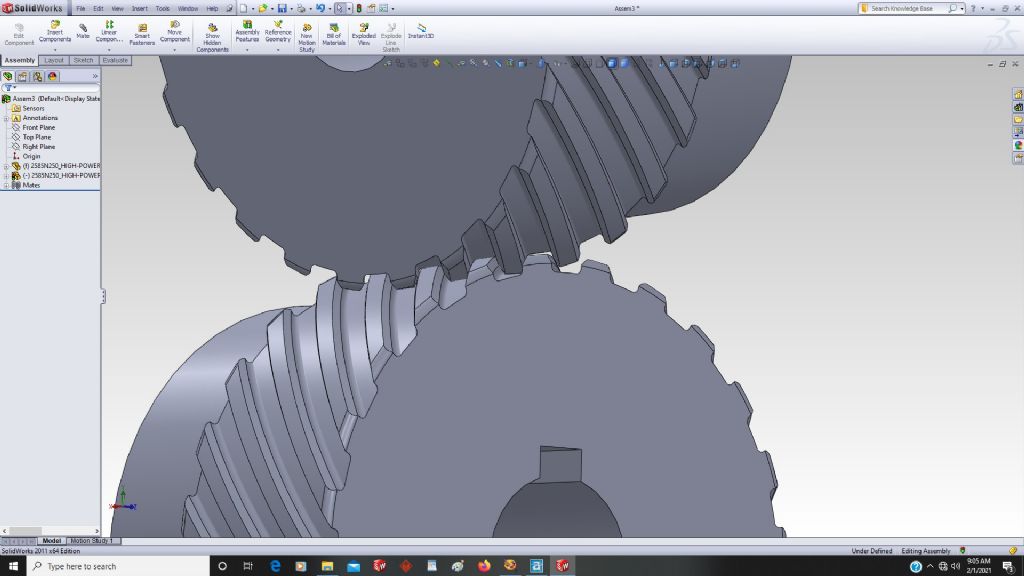
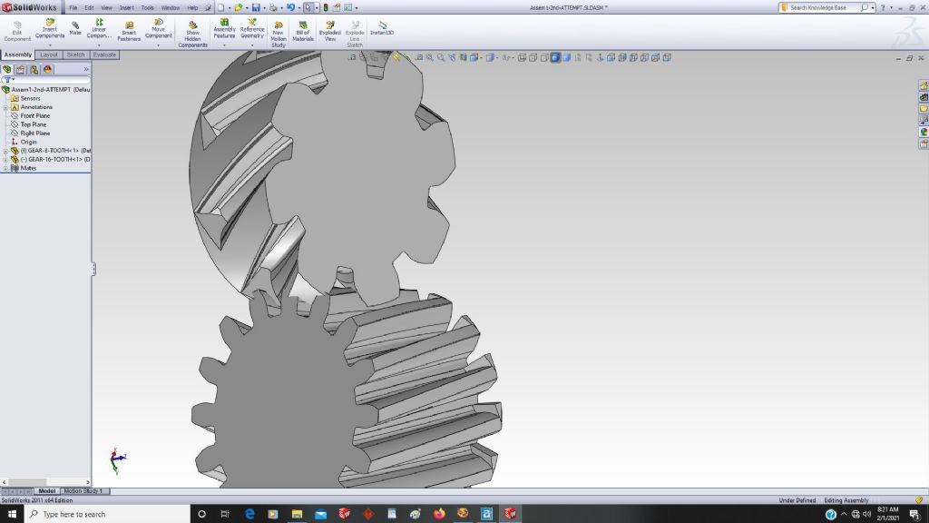
              These are the two gears with the profile downloaded from a supply house, with a 45 degree angle.

              They appear to mesh correctly when I insert them into an assembly at a 90 degree angle.

              image27.jpg


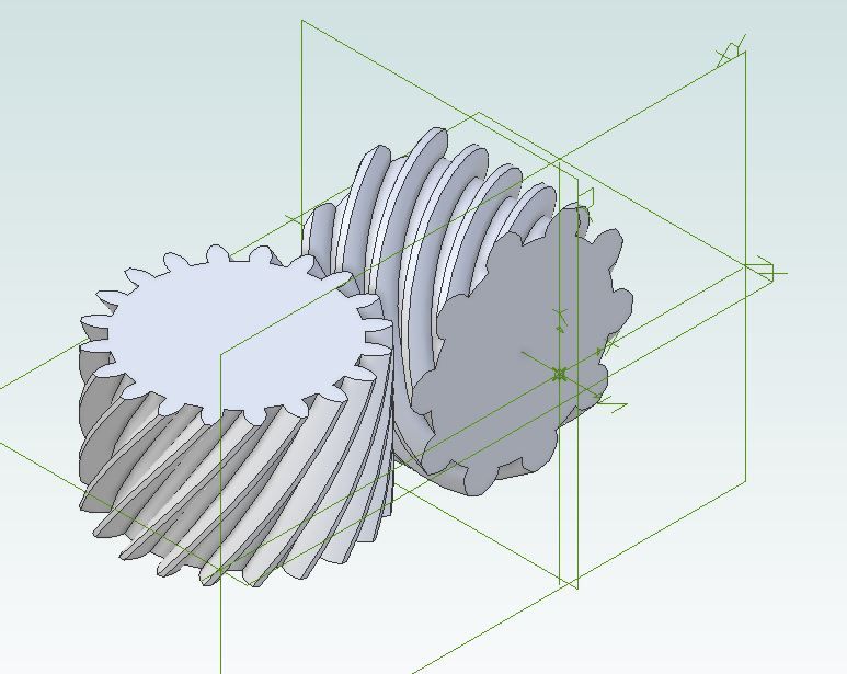
              And this is one version of my attempt at a swept cut normal to the path.

              I tried several versions of the gear with fewer teeth, but no mesh.

              It is obvious I am lost in space on this gear thing, but I will keep on chugging.

              I feel like I know more today about it than I did yesterday, so there is that.

              image24.jpg

              .


              Edited By PatJ on 01/02/2021 18:44:24

              Edited By PatJ on 01/02/2021 18:51:48

              Edited By PatJ on 01/02/2021 18:52:24

              Edited By PatJ on 01/02/2021 18:53:47

              #524199
              PatJ
              Participant
                @patj87806

                Now I see the button for toggling the angle of the helix from positive to negative.

                I needed that last night.

                It is difficult to learn every aspect of 3D software, especially when you are plowing fresh (frozen) ground.

                The only way I know to learn 3D is to create things with 3D.

                With each complete model, the knowledge base improves significantly.

                .

                Edited By PatJ on 01/02/2021 19:13:36

                #524206
                JasonB
                Moderator
                  @jasonb

                  Pat your helix angles in the last image look wrong. The gear with the fewer number of teeth wants the 26.6deg helix and the one with double the teeth needs the 53.4deg helix which should get them looking better.

                  helical pair.jpg

                  #524207
                  PatJ
                  Participant
                    @patj87806

                    Jason-

                    Thanks. Looks like there are at least two methods for creating helical gears in Solidworks, and I have been using the more difficult method, and this has created some problems.

                    I am getting ready to try the second method, and I think it will work better.

                    (26.4 and 63.4)

                    .

                    #524208
                    JasonB
                    Moderator
                      @jasonb

                      26.6

                      #524219
                      PatJ
                      Participant
                        @patj87806

                        I mis-typed.

                        26.6 and 63.4

                        #524220
                        Andy_G
                        Participant
                          @andy_g

                          The 45 degree gears will mesh because they both have the same helix angle, and hence the relationship between the normal and transverse modules will be the same for each. It looks like you're on the right path now – just getting the handedness & pitch angles the right way around.

                          If you appreciate the Antikythera mechanism, and have a day to spare….

                          Clickspring Antikythera Construction

                          #524250
                          PatJ
                          Participant
                            @patj87806

                            Andy-

                            I showed my wife the Antikythera mechanism, and asked her some questions, such as "where did they get the metal to begin with, where did they get the tools such as hacksaws, files, drill bits, etc., and then where did they get the knowledge base (by direct observation of celestial events I guess).

                            We are spoiled these days. There are perhaps 10 hardware stores just in the city that I live in, and what cannot be had there can be purchased online from around the world.


                            Jason-

                            I am inching closer to a solution on the helical gears.

                            I have the handedness correct (both gears are the same direction).

                            The second Solidworks method works much better than the initial one that I tried, however, the second method does not give an option about rotation angle, but rather length of the path, with 1 being a 360 degree rotation around the part.

                            I have proportioned the length to the angle, but that does not give the correct result, but I can manually manipulate the path length, and it looks like I am getting close to a mesh, so that is good.

                            I will rest a day, and then verify that the gear with the fewer number of teeth has the 26.6 degree angle.

                            I may have the wrong angles on the gears.

                            I must say this is a good exercise in helical gear cutting in 3D, and would be very useful for cutting actual gears also. Too bad all 3D programs are not exactly the same, but most are pretty close, and close enough to generally follow how a part is created.

                            The Solidworks "helix/spiral" command has the options "Height and Revolution", "Height and Pitch", "Spiral", "Constant Pitch", and "Variable Pitch". I vaguely recall using this function to create IC engine spring models, using a variable pitch on the helix, and a circular section.

                            For "Cut-Sweeping" the gear tooth section along the helix/spiral path, I have the following options:

                            "Orientation/Twist type":

                            1. Follow path.

                            2. Keep normal constant.

                            3. Follow path and 1st guide curve.

                            4. Follow 1st and 2nd guide curves.

                            5. Twist along path.

                            6. Twist along path with normal constant.

                            I am using selection No.6 for this item.

                            I have tried each of these items, and it seems like No.06 is the only one that comes close to working, but I need to look at this further, and understand exactly what I am doing here.


                            There there is "Define By":

                            1. Degrees.

                            2. Radians.

                            3. Turns.

                            I am using degrees, and if the circular arrow button to the left of the degrees box is pressed, the angle is flipped to the opposite hand.

                            Lots of options, which is typical of Solidworks, and all very confusing at first, but once you make a part using the methods needed, then it is just a matter of making note of the exact settings that were used, or pulling up a previously made part and duplicating those settings (I don't have any previously made helical gear models, yet).

                            Better to have many options and not use them all than to have too few options and not have something that you may need.

                            I can see that this can most likely be worked out in 3D (by me).

                            Its always easy to watch someone else do things, and not so easy to duplicate that effort sometimes.  This seems to be true with metal casting also.

                            Looks like I used the 26.6 degrees for the gear with the larger number of teeth, so I will rework the angles, and try again tomorrow.

                            I owe you folks for all the hand-holding through this effort. Hats off to all of you.

                            I appreciate it.

                            .


                            Edited By PatJ on 02/02/2021 05:51:27

                            Edited By PatJ on 02/02/2021 05:52:07

                            Edited By PatJ on 02/02/2021 05:54:03

                            Edited By PatJ on 02/02/2021 05:54:57

                            #524257
                            JasonB
                            Moderator
                              @jasonb

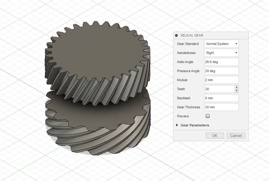
                              A quick Google last night found a free app for Fusion360 that will generate helical gears and it's dead easy to use simply enter the few items in the box one of which is the helix angle and if the Module (or DP) is left the same it will produce two gears of the same diameter if you halve the number of teeth with teeth running at the two angles – you need to do it once for each gear. I'm not good enough at the CAD side of F360 to move them into mesh!

                              This could be very useful for those building small IC engines where the old sources of helical timing gears have dried up and it would be easy to generate a pair of gears and have them metal printed or investment cast for a reasonable sum

                              f360 helical.jpg

                              If doing the helical cut the pitch can be calculated quite easily with a bit of Trig as the circumference can be calculated and we know from rod the helix angles so the pitch can be worked out see image here

                              #524264
                              JasonB
                              Moderator
                                @jasonb

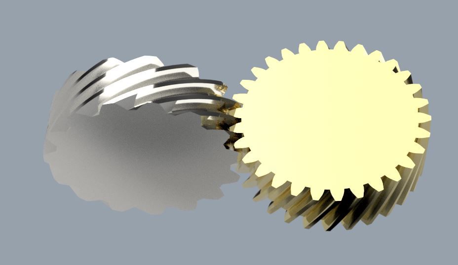
                                I got them to mesh and polished them up a bit while I was at it. The silver 15T gear on the crankshaft will drive the 30T gold cam gear giving the correct ratio.

                                pats gear mesh.jpg

                                #524275
                                Andy_G
                                Participant
                                  @andy_g
                                  Posted by JasonB on 02/02/2021 07:36:40:

                                  A quick Google last night found a free app for Fusion360 that will generate helical gears and it's dead easy to use

                                  Hi Jason – that’s the same one as I found (above). It does seem to work very well!

                                  #524278
                                  Andy_G
                                  Participant
                                    @andy_g
                                    Posted by PatJ on 02/02/2021 05:49:59:

                                    Andy-

                                    I showed my wife the Antikythera mechanism, and asked her some questions, such as "where did they get the metal to begin with, where did they get the tools such as hacksaws, files, drill bits, etc.,

                                    off topic: If you explore the Clickspring channel, he makes the metal, drill bits, files, etc. using contemporary technology. It really is remarkable.

                                    #524295
                                    Roderick Jenkins
                                    Participant
                                      @roderickjenkins93242
                                      Posted by PatJ on 02/02/2021 05:49:59:

                                      The second Solidworks method works much better than the initial one that I tried, however, the second method does not give an option about rotation angle, but rather length of the path, with 1 being a 360 degree rotation around the part.

                                      Pat,

                                      If you know the lead (length of path) of the helix then you just need to rotate your gear profile through one rotation in the lead length. This is the spreadsheet I put together to calculate my gears and it shows the equations I used. I was using Brown & Sharpe cutters to make my gears so the spreadsheet is geared (!) towards that end.

                                      helical spreadsheet.jpg

                                      Send my a PM if you would like a copy of the Excel file.

                                      HTH,

                                      Rod

                                      #524303
                                      PatJ
                                      Participant
                                        @patj87806

                                        Thanks again Jason.

                                        This is great information. I don't use Fusion360, but it is still good to know about.

                                        Rod-

                                        I will send you a PM.

                                        Pat J

                                        #527028
                                        PatJ
                                        Participant
                                          @patj87806

                                          I started a 3D print on my Prusa of Jason's two gears.

                                          The print kept lifting off the bed.

                                          I tried the purple glue, but that did not help at all.

                                          I cleaned the bed, but again to adhesion.

                                          I have never really had adequate time to play around with my Prusa and really understand it, so today I started playing with print head heights.

                                          I went into head height adjustment, and cranked the head down with a piece of paper below the head, to the point where there was slight tension on the paper.

                                          This setting was at -0.425 (don't know what units this is), and this did not work.

                                          I raised the head to -0.355, and this is now working well.

                                          I watched the Prusa video again an head height adjustment, this time with closed captions on.

                                          This time I was able to pick up what Prusa said, which was "the correct head height adjustment is critical for first layer adhesion".

                                          In the past, I had tried to eyeball the head height, and approximate what looked correct by observing the filament stream shape.  This method did not work well at all, and I was unable to find the correct height by using the visual method.

                                          The method I mention above with the paper seems to work like a charm, and I did not clean the bed between the first two attempts and the attempt that is now working. So it is not so much a clean bed problem, as it is a head height adjustment problem, and a first layer adhesion problem due to improper head height.

                                          I understand that the bed must be kept clean, but when a clean bed will not adhere, then it may be a print head height problem, as I discovered today.

                                          So I am printing Jason's gears, and will be checking them for mesh.

                                          If all goes well I may attempt a casting, but the weather will have to get a bit warmer.

                                          We are anticipating single digit F temperatures tonight, and the houses in this region are not set up for this temperature, so the plumbers will be super busy next week.

                                          I am getting ready to put heat lamps on my outside hose bibs.

                                          Its the only solution for single digit temps, other than using heat trace cable, which would be difficult to install after the fact.

                                          slicer-01.jpg

                                          Edited By PatJ on 13/02/2021 22:17:35

                                          Edited By PatJ on 13/02/2021 22:19:05

                                          #527029
                                          PatJ
                                          Participant
                                            @patj87806
                                            I reviewed some information I had previously found about helical gears operating at 90 degrees, which is as follows:
                                            .
                                            1. Two helical gears of the same diameter with teeth cut at 45 degrees will operate at a 1:1 speed ratio, and we know they will mesh correctly.
                                            .
                                            2. Two helical gears can operate at 90 degrees to each other if the gears are both of the same hand, ie: either both left-hand helix or right-hand helix.
                                            .
                                            3. In order for two helical gears operating at 90 degrees to mesh, they must have the same pitch and pressure angle.
                                            .
                                            4. From McMaster Carr: "To change speed and torque in your assembly, pair two gears with different numbers of teeth".
                                            .
                                            I always assumed that using two gears with different numbers of teeth meant using two gears of two different sizes, and it still baffles me that two gears of the same diameter can have different tooth counts.
                                            .
                                            I also made the false assumption that the angle of the helix had something to do with the ratio, but was overlooking the obvious.
                                            .
                                            The speed ratio of two helical gears and associated shafts is related to the number of teeth on the two gears, and a 2:1 ratio of teeth gives a 2:1 ratio of speed.
                                            .
                                            So that begs the question, why use a special helix angle that is not exactly 30/60 degrees?
                                            Why not use 25/65, or 35/55 degrees.
                                            It would seem that any helix angle would work as long as the sum of the angles adds to 90 degrees.
                                            .
                                            It is the mesh that makes the helix angle critical ?

                                            Edited By PatJ on 13/02/2021 22:28:40

                                            Edited By PatJ on 13/02/2021 22:29:21

                                            Edited By PatJ on 13/02/2021 22:30:17

                                            Edited By PatJ on 13/02/2021 22:30:50

                                            #527053
                                            PatJ
                                            Participant
                                              @patj87806

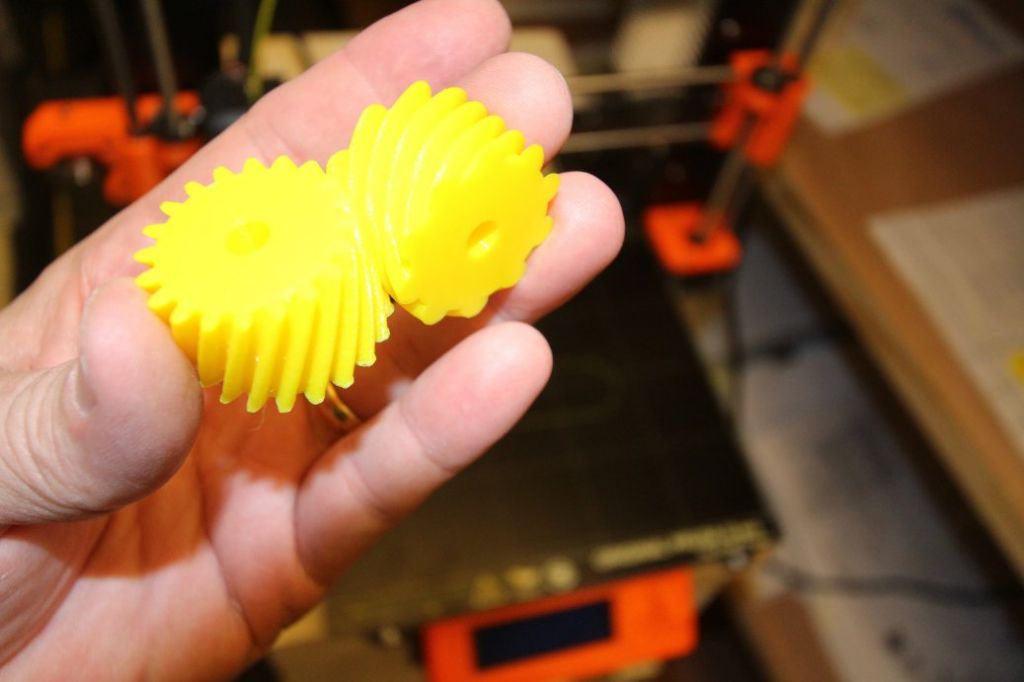
                                              And after getting my Prusa print head adjusted to the right height, which solved my bed lifting problem, I was able to print both gears at the same time.

                                              They mesh perfectly, and the surface finish is quite good.

                                              It amazes me how these gears mesh and work so well.

                                              You nailed it Jason B !!!!

                                              Next I will make a resin-bound mold, heat these patterns, and carefully retract them from the sand.

                                              I will probably try an aluminum casting first.

                                              This is such cool technology.

                                              Designed by JasonB, and sent across the world with a touch of a button.

                                              Perfect fit.

                                              Thanks again Jason. Too cool.

                                              rimg_9015.jpg


                                              rimg_9020.jpg

                                              Edited By PatJ on 14/02/2021 04:41:55

                                              Edited By PatJ on 14/02/2021 04:42:34

                                              Edited By PatJ on 14/02/2021 04:42:54

                                              Edited By PatJ on 14/02/2021 04:43:32

                                              #527058
                                              JasonB
                                              Moderator
                                                @jasonb

                                                Pat, regarding the angles, as I hinted to in a previous post when working out the helix height for one revolution when you work back from the angles Rod gave it all becomes clear.

                                                Take another look at the second image on this site where the triangle is wrapped around the cylinder. If the 26.6 and 63.4 are used then using TRIG to work out the two sides of the triangle the base is 2 and the vertical 1 which ties in very well with the 2:1 ratio of the gears.

                                                If we did not already know the helix angle but knew the ratio then the angles for a triangle of Xbase x Yheight can be worked out.

                                                Gears look good, keep us posted on the casting progress.

                                                #527270
                                                PatJ
                                                Participant
                                                  @patj87806

                                                  Jason-

                                                  That is good information, and makes slightly more sense as far as where the angles were derived, but I still have questions, and it seems like we are dancing around the answers, so here are my questions, if you have the patience for endless query about this topic:

                                                  1. Will two helical gears mesh and operate properly at 90 degrees if the angle is not 26.6 and 63.4, as long as the sum of both angles equals 90 (yes/no) ?

                                                  2. Is the 2:1 shaft speed ratio determined by the 2:1 teeth count or the ratio of the angles? (don't say both or I shall have to scream).

                                                  I should not be lazy, and I should make up a few gears, 3D print them, and try it for myself.

                                                  Things that do make sense as far as trying to relate helical gears to spur gears (which may be a false analogy) is that the gear with 10 teeth rotates twice for every rotation of the gear with 20 teeth (I would expect this).

                                                  And this gear arrangement seems to operate much like a worm gear arrangement, except both gears are the same diameter, whereas with worm gears, generally a small gear drives a larger gear.

                                                  .


                                                  Edited By PatJ on 14/02/2021 18:11:05

                                                  Edited By PatJ on 14/02/2021 18:11:39

                                                  #527272
                                                  JasonB
                                                  Moderator
                                                    @jasonb

                                                    1. No At least not for 2:1 ratio

                                                    2. Yes

                                                    #527352
                                                    PatJ
                                                    Participant
                                                      @patj87806

                                                      So are you saying that you could have used 8 and 16 teeth, or 12 and 24, as long as the correct angle is worked out?

                                                      .

                                                    Viewing 25 posts - 26 through 50 (of 61 total)
                                                    • Please log in to reply to this topic. Registering is free and easy using the links on the menu at the top of this page.

                                                    Advert

                                                    Latest Replies

                                                    Viewing 25 topics - 1 through 25 (of 25 total)
                                                    Viewing 25 topics - 1 through 25 (of 25 total)

                                                    View full reply list.

                                                    Advert

                                                    Newsletter Sign-up