3 cyl Pip engine

Advert

3 cyl Pip engine

Home Forums Work In Progress and completed items 3 cyl Pip engine

Viewing 25 posts - 1 through 25 (of 167 total)
  • Author
    Posts
  • #386143
    David K
    Participant
      @davidk77137

      Hi , I recently built a 3 cylinder 'PIP' engine from plans purchased at LittleLocos.com. I wrote a build thread on another forum I use so I thought I may transfer it across to here. Bear with me as this forum works a little differently to the one I am used to.

      First job is to make a 2mt taper with a 1/2 inch round boss on the end.
      This will fit into my rotary table and my lathe nose and will enable me to
      swap work pieces quickly while keeping them centred.
       Then machine a 1/2'' hole into my Cylinder blanks to fit the taper and also a 1/4'' grove
      to use for holding clamps. I am making four cylinders so I have a spare in case something
      goes wrong. The Cylinders are the most complex part apparently.
      You can see the taper fitted into the last blank.
      The first blank is mounted to the lathe using the taper and face plate.
      First job is to open out a bore to .75'' , the combustion chamber is formed by a standard
      118 degree 11/16 drill bit then the bore is opened out to .75 ready to fit a steel sleeve
      later in the build.
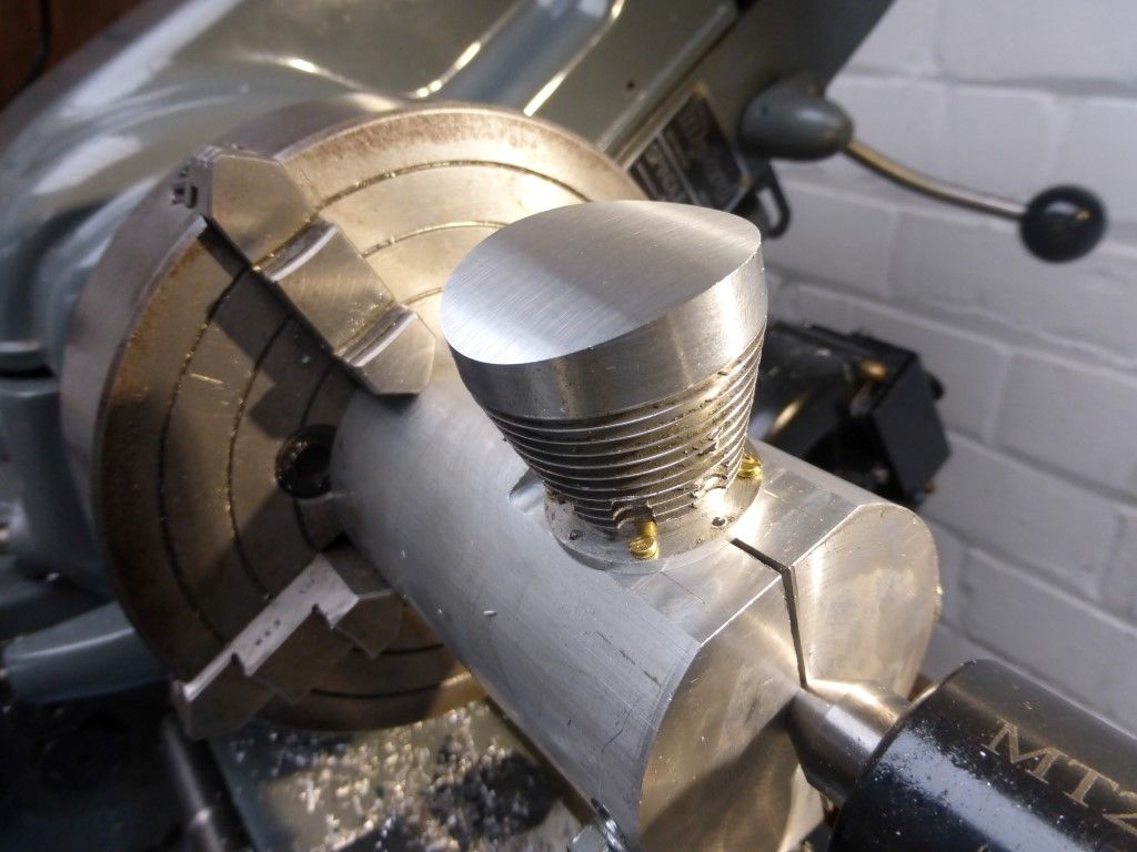
      The outside shape of the Cyl is then formed by turning a 30 degree taper leaving
      a mounting boss on the end.

      Edited By David Kenyon 2 on 17/12/2018 19:09:57

      Edited By David Kenyon 2 on 17/12/2018 19:37:44

      Advert
      #31240
      David K
      Participant
        @davidk77137
        #386145
        JasonB
        Moderator
          @jasonb

          David once you paste the text from the other forum you will need to go through it and remove the IMG codes and cut and paste the URL between them into the Image icon at the top of the editing screen.

          I'll do what you have already posted as you may not be able to get back to edit it.

          EDIT, looks like you got there first

          Edited By JasonB on 17/12/2018 19:16:41

          #386147
          David K
          Participant
            @davidk77137

            Hi , yes realised this forum works differently so I am just working things out so I can post the pictures.

            #386160
            David K
            Participant
              @davidk77137
              I ground a slight taper onto a 3/32 parting blade and rounded the end. This was used
              to cut the fins and also reduce the thickness of the boss .
              The DRO I fitted recently was a godsend for this job.
              First one done , just another three to do
              ]
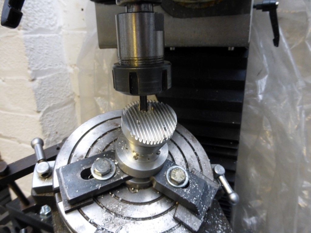
              The 2mt was removed from the lathe and fitted to my rotary table then centred on my mill.
              First cylinder fitted and the eight [2mm ] mounting holes drilled in the boss
              ]
              #386168
              Emgee
              Participant
                @emgee

                Interesting topic, keep posting please.

                Emgee

                #386323
                David K
                Participant
                  @davidk77137

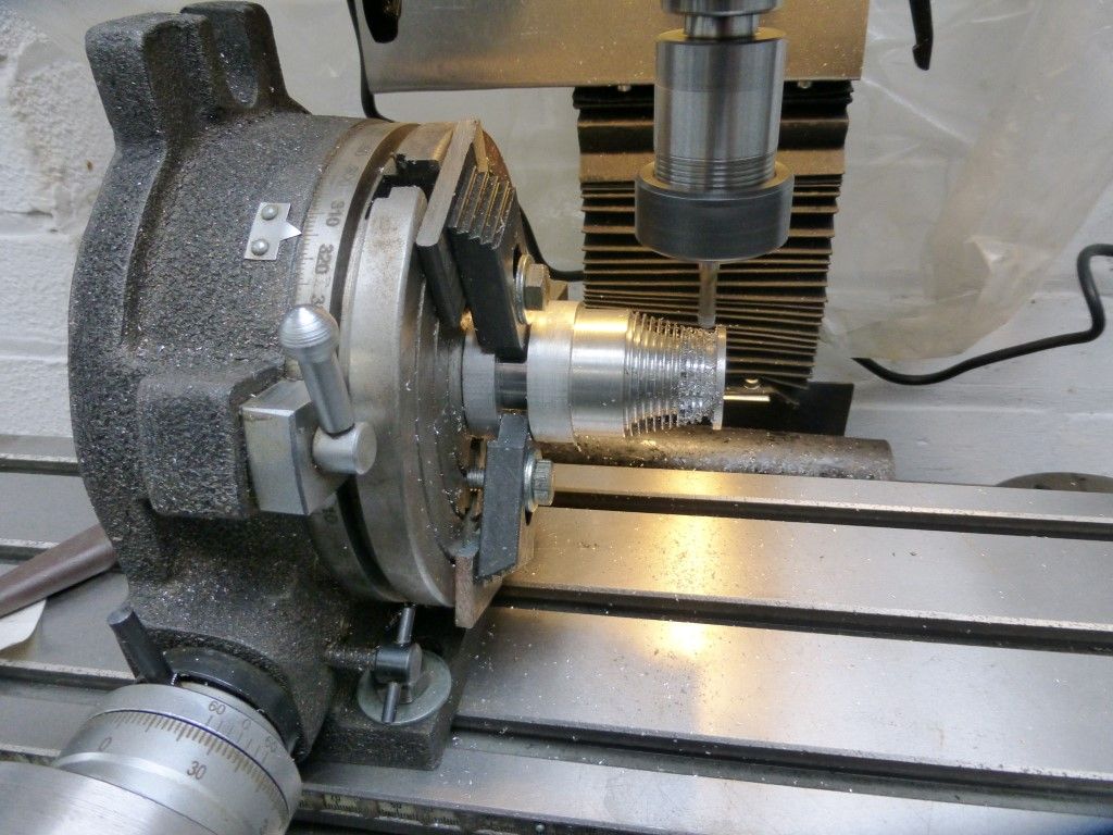
                  The rotary table is set up horizontal on the mill table and a milling cutter is used to

                  mill through the first two fins opposite each of the eight mounting holes.

                  This provides clearance for the mounting screws to be fitted later.

                  p1030340 (medium).jpg

                  #386330
                  David K
                  Participant
                    @davidk77137

                    That's all the work from the bottom of each cylinder so I now part off each one from its mounting.

                    One mounting is then drilled and tapped m2 to match the cylinder boss and this will be used

                    for mounting the cylinders for future work on the top end.p1030342 (medium).jpg

                    #386332
                    David K
                    Participant
                      @davidk77137

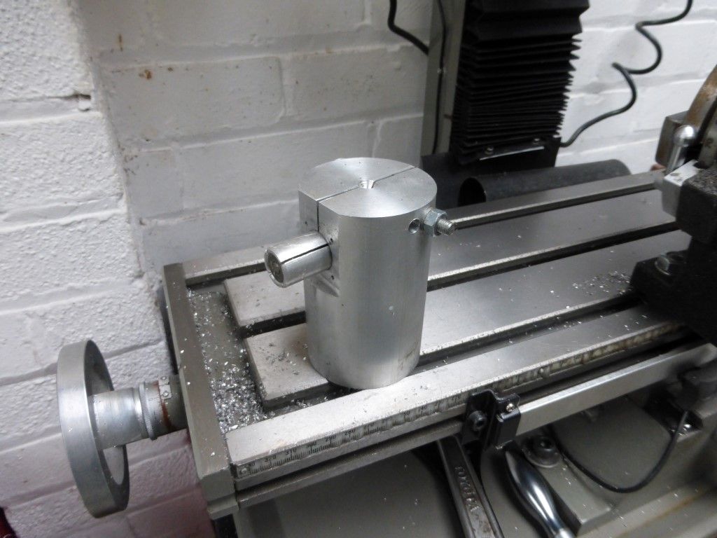
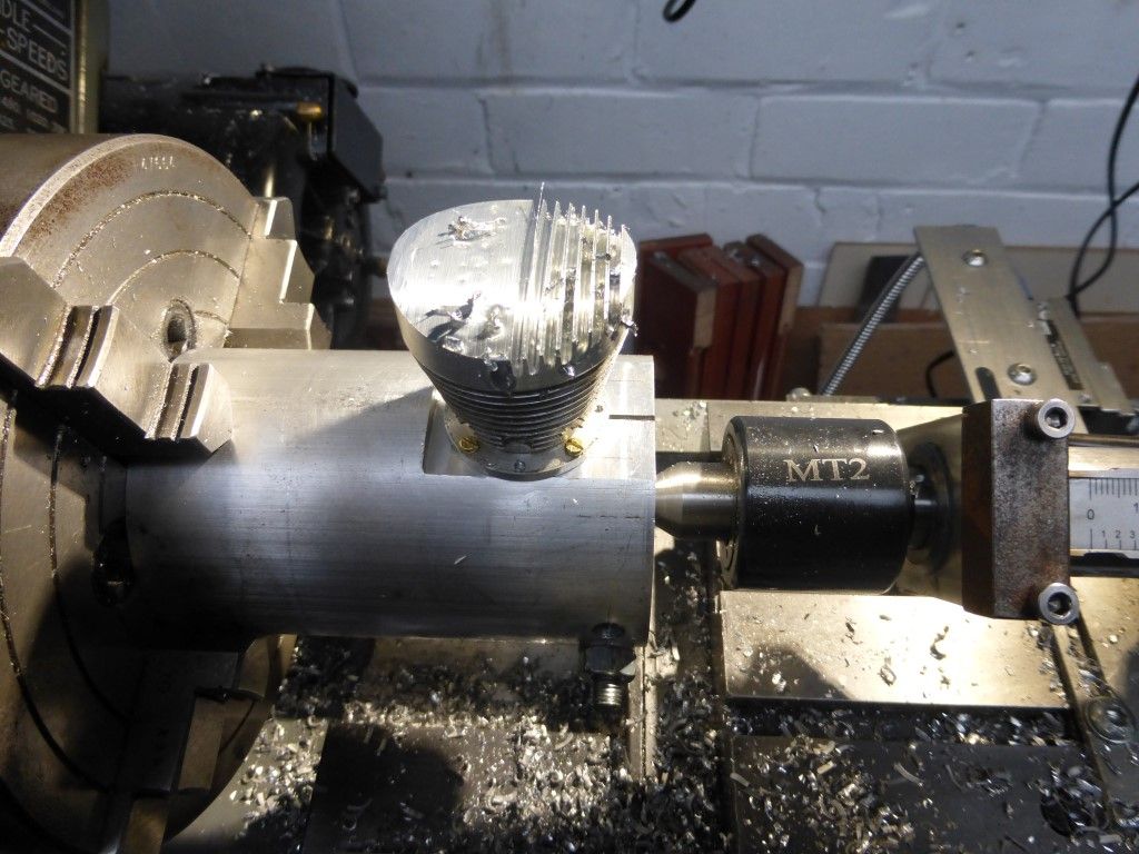
                      Had to make a jig to hold the Cyl for the top fins to be cut.

                      This consists on a large chunk of alloy rod with an expanding mandrel

                      fitted through at 90 degrees as below p1030528 (medium).jpg

                      #386333
                      David K
                      Participant
                        @davidk77137

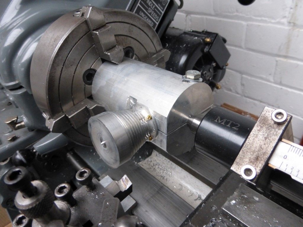
                        here you can see the set up with a cylinder bolted and the mandrel tightenedp1030344 (medium).jpg

                        #386335
                        David K
                        Participant
                          @davidk77137

                          First the top of cylinder is turned to shapep1030348 (medium).jpg

                          #386338
                          David K
                          Participant
                            @davidk77137

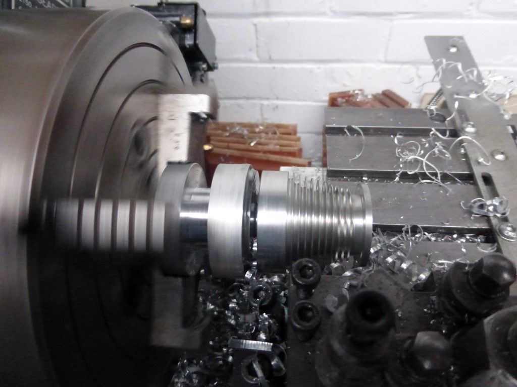
                            The same form tool is then used to cut the fins. The lathe is set to 70 rpm using the back gear and

                            the tool is fed in slowly whilst lubricating with oil. Took ages but quite satisfying listening to the tool

                            taking long shavings off a bit like a wood plane.p1030347 (medium).jpg

                            #386383
                            Ady1
                            Participant
                              @ady1

                              You may find a lack of replies disconcerting at first, it's so we don't clutter a good build thread like this one

                              #386398
                              JasonB
                              Moderator
                                @jasonb

                                You are making good progress, I had to double check the drawings as I thought the fins were running the wrong way but the curved top runs front to back as the cylinder gets turned through 90 deg after machining the fins.

                                #386488
                                David K
                                Participant
                                  @davidk77137
                                  Posted by Ady1 on 18/12/2018 23:20:43:

                                  You may find a lack of replies disconcerting at first, it's so we don't clutter a good build thread like this one

                                  That's ok, I am copying and pasting from another forum so it easy enough now I have sussed the pictures.

                                  The other forum was not an engineering forum so you may find some of the explanations a bit brief / simplistic.

                                  #386494
                                  David K
                                  Participant
                                    @davidk77137

                                    With the lathe work complete the next step is to machine the holes for the

                                    valve guides and hot plug using the mill.

                                    The holes will need drilling radially at a 30 degree angle and enter the tight combustion

                                    chamber accurately.

                                    To help me set up the drill I had to make another jig seen below with a cylinderp1030353 (medium).jpg

                                    #386496
                                    David K
                                    Participant
                                      @davidk77137

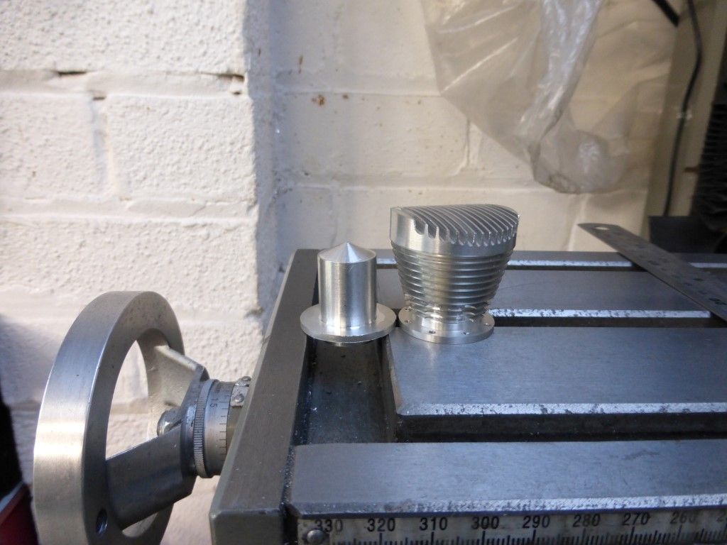
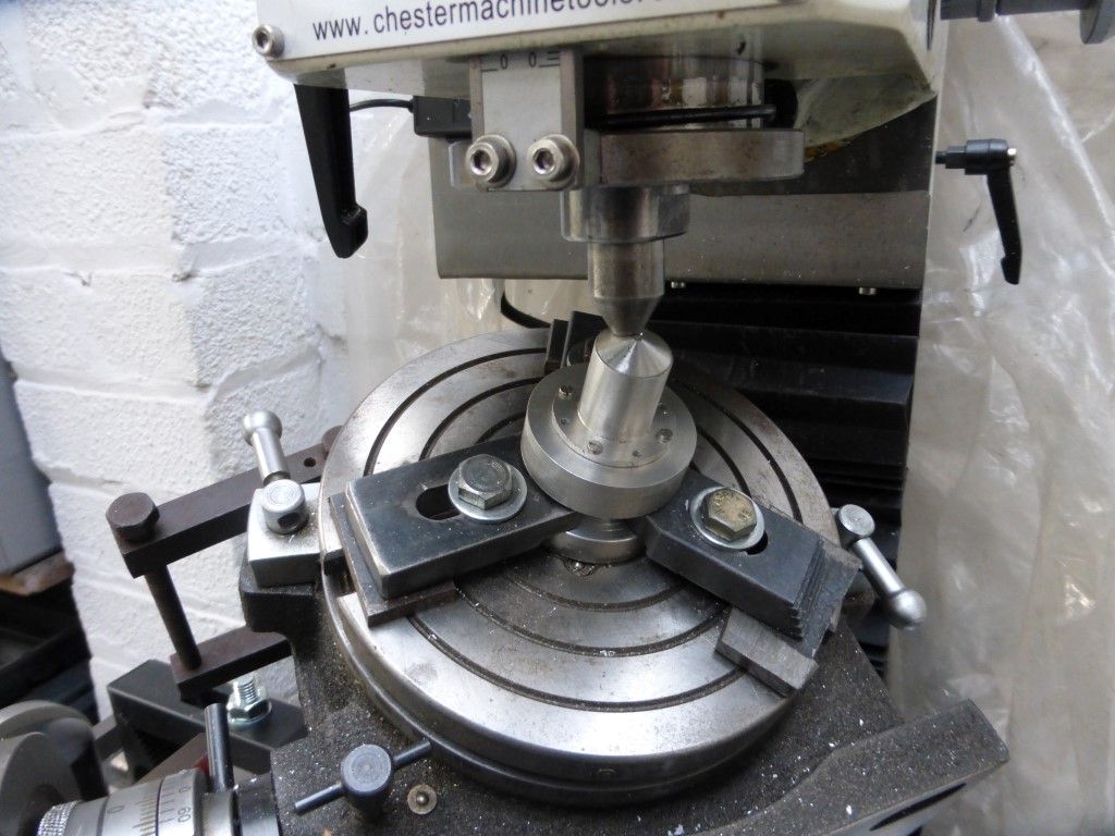
                                      The jig is a copy of the internal bore and combustion chamber shape and is set up on the mill

                                      at a 30 degree angle so the top is level . A taper is drilled dead centre of the flat using a centre drill

                                      and this is then used to centre the jig on my mill as blow.


                                      p1030457 (medium).jpg

                                      #386497
                                      David K
                                      Participant
                                        @davidk77137

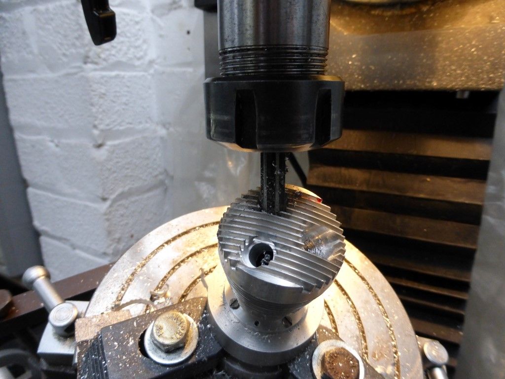
                                        So with the first cylinder fitted in place of the jig I set the table to zero degrees

                                        and line the top fins so the drill enters dead centre.

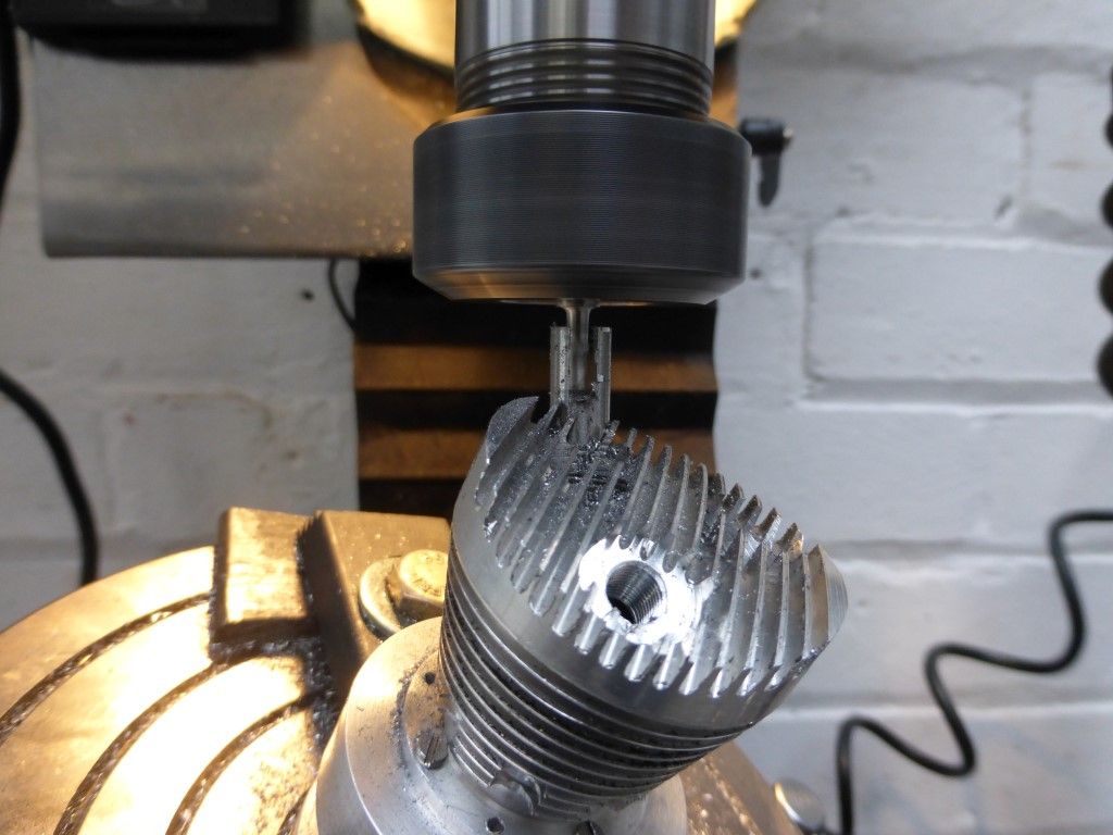
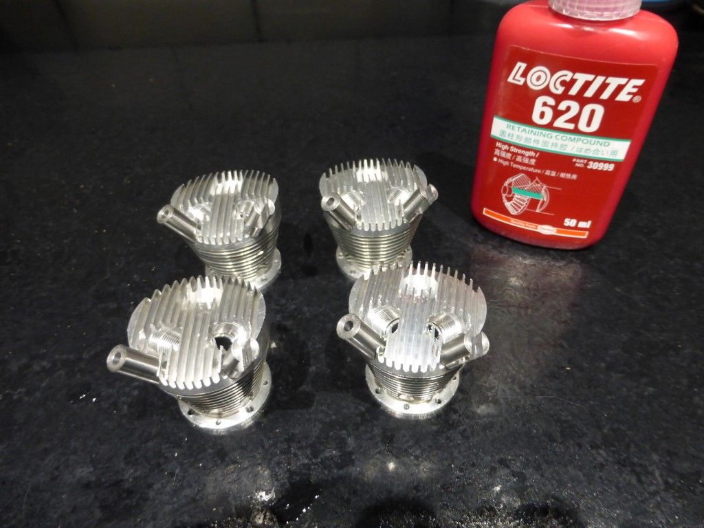
                                        First hole is for the glow plug, a mill is used to turn down the fins until a flat is

                                        formed on the cylinder head, then centre drill , drill and finally tap 1/4 – 32 thread.

                                        p1030460 (medium).jpg

                                        #386498
                                        David K
                                        Participant
                                          @davidk77137

                                          The table is turned 120 degrees ready for drilling the valve guide seat. This is a bit more involved.

                                          First mill a flat, then drill 7.6mm, ream 8mm, then drill down 9mm but stop about 1/16'' from the bottom.

                                          Then tap M10 fine, again just short of the bottom. A 45 degree taper will be cut on the shoulder at the bottom

                                          were the m8 is left.

                                          The table is turned another 120 degrees and the second valve guide seat is cut.p1030466 (medium).jpg

                                          #386499
                                          David K
                                          Participant
                                            @davidk77137

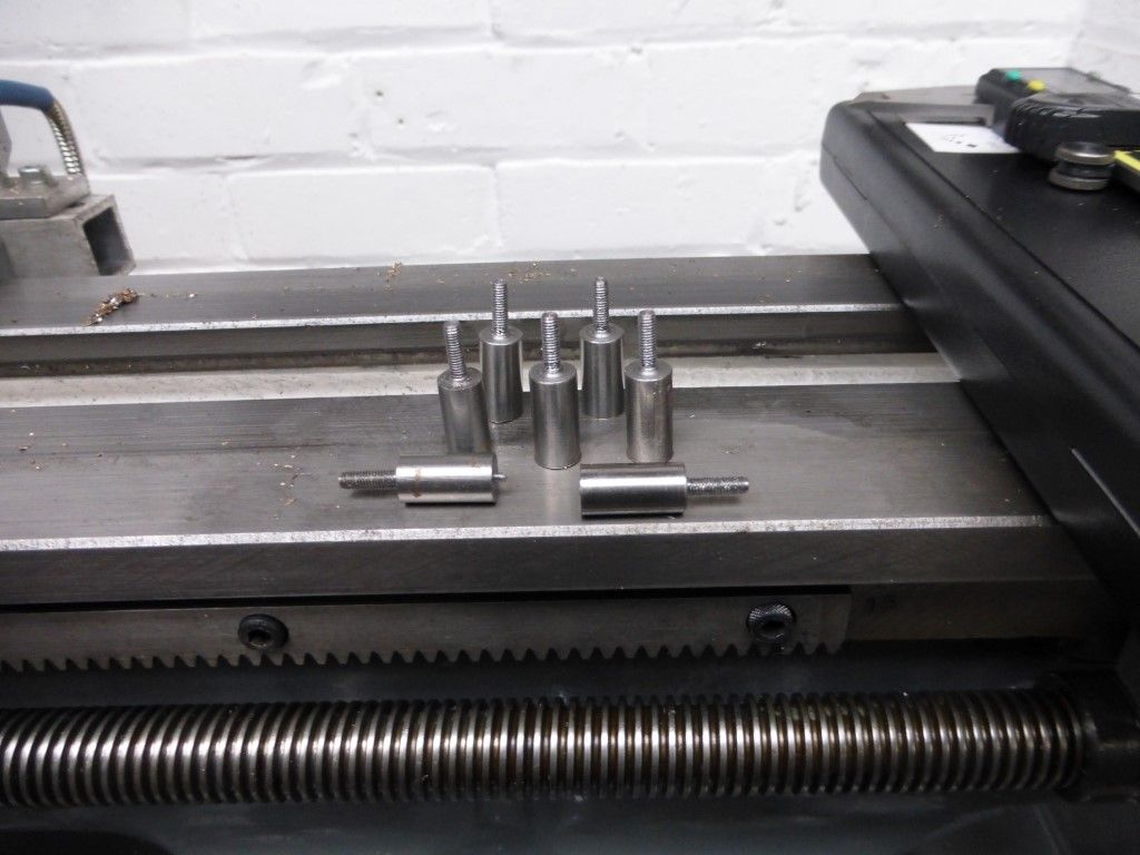
                                            I then had to turn some threaded posts for the rocker arm pivots. They are just Silver steel with an M3 thread. p1030497 (medium).jpg

                                            #386500
                                            David K
                                            Participant
                                              @davidk77137

                                              Remember the set up on the mill was turned 49 degrees , that is because the rocker posts are

                                              fitted at a 49 degree angle from the valves.

                                              So while centred over the valve guide I offset the table 0.344'' and drill / tap a m3 thread, a post is

                                              screwed in with permanent Loctite and then a slot is milled to accept a rocker. p1030478 (medium).jpg

                                              #386502
                                              David K
                                              Participant
                                                @davidk77137

                                                Here you can see the cylinders just needing the second slot finishing on the left

                                                hand rocker postsp1030479 (medium).jpg

                                                #386505
                                                David K
                                                Participant
                                                  @davidk77137

                                                  With the cylinders drilled and tapped I need to make the valve seats/guides.

                                                  These are made n one piece out of 660 phosphor bronze.

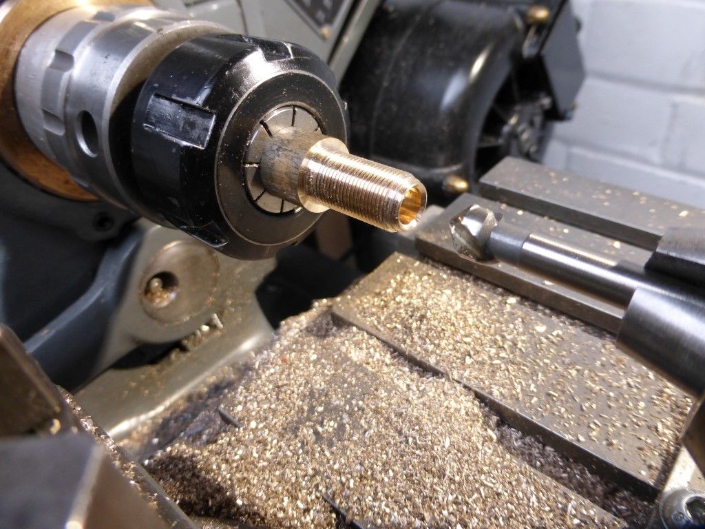
                                                  A piece of bronze is turned down and threaded m10 fine to match the Cylinder, then

                                                  the first 2mm is turned down to 8mm and the step is turned a 45 degree taper.

                                                  #386506
                                                  David K
                                                  Participant
                                                    @davidk77137

                                                    continued from above

                                                    This taper will be the seat for the guide when screwed into the cylinder.

                                                    A 3mm hole is then drilled and reamed through the centre, the front half is opened

                                                    out to 6.5 mm then a 45 degree valve seat is formed as in the pic below. p1030473 (medium).jpg

                                                    #386507
                                                    David K
                                                    Participant
                                                      @davidk77137

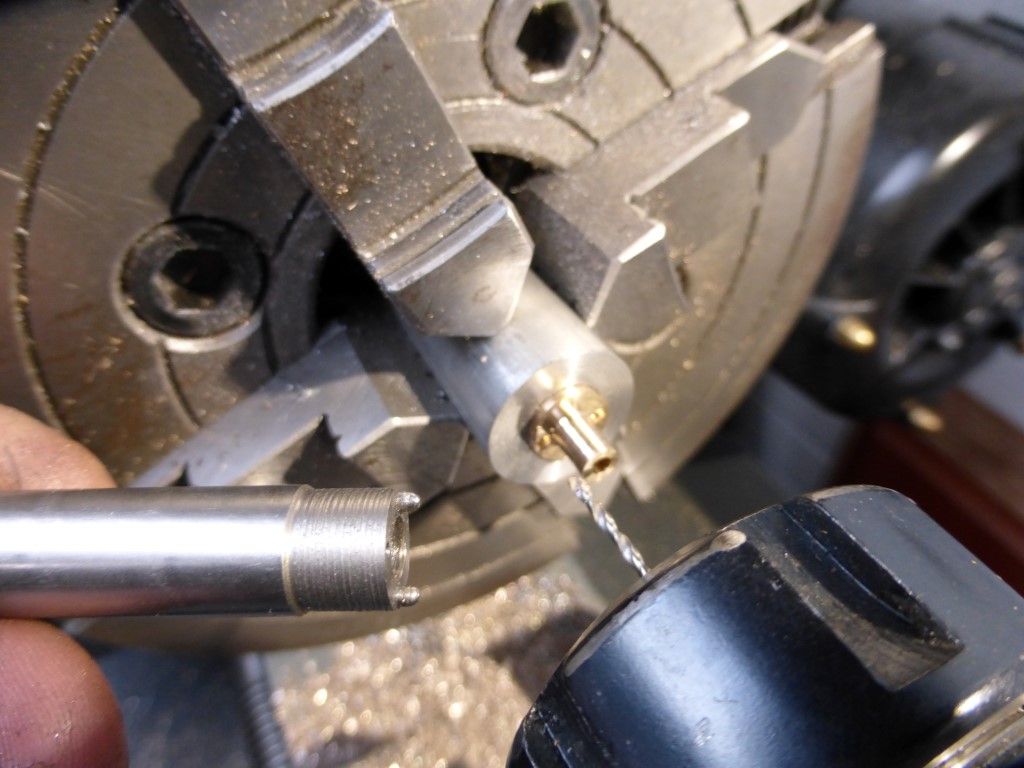
                                                      I then placed a bit of alloy in the lathe , tapped it m10 and screwed the guide into this

                                                      so I can reduce the top halve to form the guide. Two small holes are drilled either side

                                                      of the valve guide and a tool is made to insert into these which will allow me to screw the

                                                      guides in.p1030474 (medium).jpg

                                                    Viewing 25 posts - 1 through 25 (of 167 total)
                                                    • Please log in to reply to this topic. Registering is free and easy using the links on the menu at the top of this page.

                                                    Advert

                                                    Latest Replies

                                                    Viewing 25 topics - 1 through 25 (of 25 total)
                                                    Viewing 25 topics - 1 through 25 (of 25 total)

                                                    View full reply list.

                                                    Advert

                                                    Newsletter Sign-up