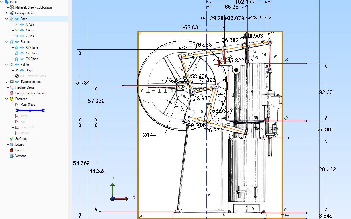
…I can’t see to find any refrence dimensions to place the feature in the centre of the attached photo. There’s enough dimensions to draw it and place it horizontally, but nothing to indicate a vertical measurement. Am I missing something? Can anyone advise me?

Like as not as others suggest it’s cosmetic and doesn’t matter much. Or a mistake, missed because it doesn’t matter much! Old plans often have a few blunders, finding them is almost a rite of passage.
Looking at the proportion relative to the measured inset beneath, it’s a shade more than ⁵⁄₁₆”. Given this is a fractional drawing, I guess ⅜”, maybe ⁷⁄₁₆”.
A CAD advantage is different positions can be tried without doing much work. You certainly don’t have to find it’s wrong by making one for real. Dunno about SolidWorks, but SolidEdge lets me select and drag features like that around the model, and it’s very easy to fiddle in 3D until it looks right.
What you’re doing is an excellent way of developing CAD skills and flushing out problems in 2D plans, ancient and modern!
Dave
SillyOldDuffer.


