3 1/2 inch small boilered TICH

Advert

3 1/2 inch small boilered TICH

Home Forums Work In Progress and completed items 3 1/2 inch small boilered TICH

Viewing 25 posts - 201 through 225 (of 303 total)
  • Author
    Posts
  • #268868
    Ryan Norton
    Participant
      @ryannorton40317

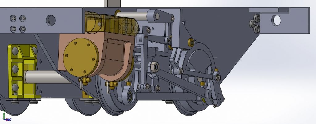
      I have had a question poised by a member regarding the full forward and reverse gear of Tich and the related movement of the die block in the expansion link. Following our chat I have had a look at my Solidworks model and found a similar concern.

      See below:

      I have had a look at my CAD drawings and the originals in the book and I have kept the dimensions of the reach rod the same. So between centres the holes are 160.337mm apart (6 5/16&quot. I have taken some screen shots to show you. It seems that I have the same problem…

      Here is the model in mid-gear, middle of expansion link.

      tich mid-gear.jpg

      Here is 15 degrees backwards (limit of sector plate)

      tich 15 degrees backward.jpg

      Here is the die block at the bottom of the expansion link (20 degrees).

      tich 20 degrees backward.jpg

      Full forward gear (limit of sector plate)

      tich full forward gear.jpg

      Die block at top of expansion link

      tich die block at very top of expansion link.jpg

      The amount of overrun on the sector plate seems like a lot but the difference between the obtainable full gear and the movement of the die block in the expansion link does not. I am almost sure that LBSC just made the expansion over-sized.

      I think that it would make sense for the full forward and reverse gear to have correlated movements of the die block to the extremes of the expansion link, but it does not seem so here.

      Can anyone shed some light on the above?

      Regards

      Ryan

      Advert
      #268894
      julian atkins
      Participant
        @julianatkins58923

        Hi Ryan,

        You have approached the problem from the wrong way.

        You need to work out the correct valve events in fullgear, then work back from this.

        I always make the reverser to suit the gear.

        You need to be avoid overrun of the valves in fullgear.

        You really ought to run the Tich valve gear on a computer simulator for valve gears, though I am not aware of any particular errors in LBSC's gear as designed. Some fine tuning has been done to LBSC's Juliet, but I am not aware this has been done for Tich.

        Cheers,

        Julian

        #268904
        Ryan Norton
        Participant
          @ryannorton40317

          Hi Julian

          You are right, I never thought of it that way, after all, correct valve events are what count ultimately.

          I have dabbled with some simulation software in the past but never really got it working properly, I suppose now Ill have to…

          I do however think that the Tich valve gear is fine for normal operation as there have not been many complaints. Maybe if one were to optimise it further, there may be some changes to be made.

          Thanks again Julian

          #269867
          Ryan Norton
          Participant
            @ryannorton40317

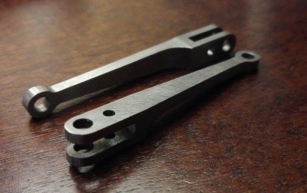
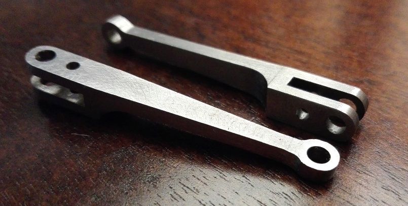
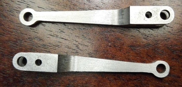
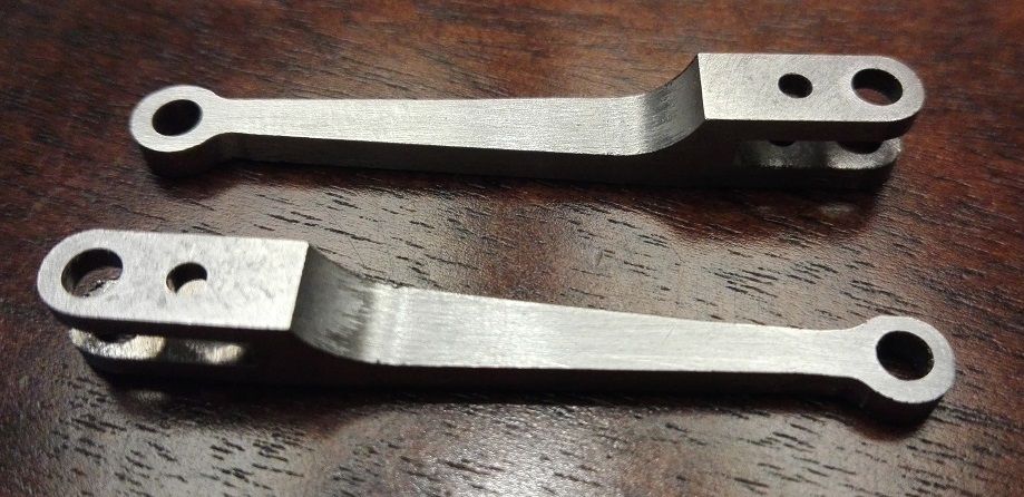
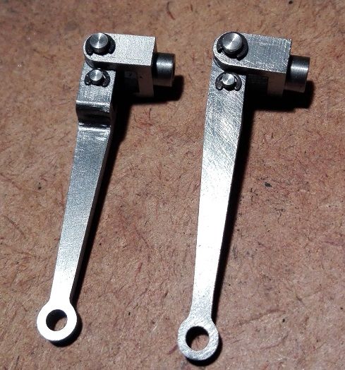
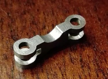
            I have almost completed the combination levers. all that is to be done now is to convert the nice clean sharp edge into a radius.

            comb lever 021.jpg

            comb lever 022.jpg

            comb lever 023.jpg

            comb lever 024.jpg

            I am fairly happy with my filing, possibly a couple of bits here and there to clean up.

            #270430
            Ryan Norton
            Participant
              @ryannorton40317

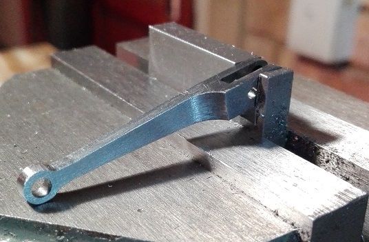
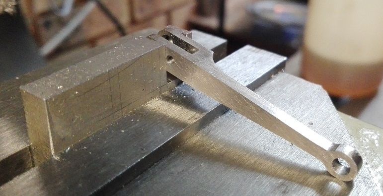
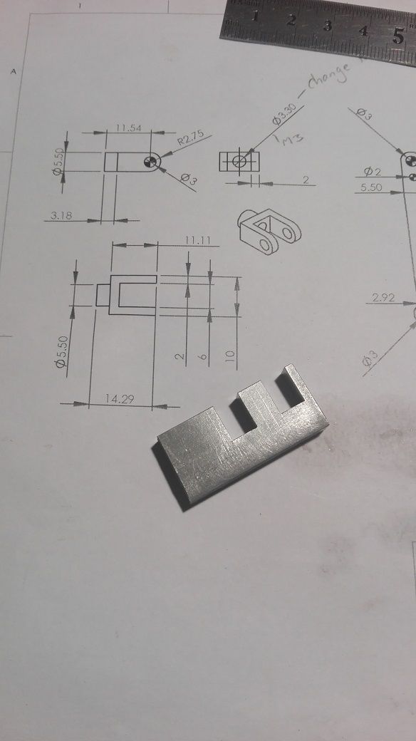
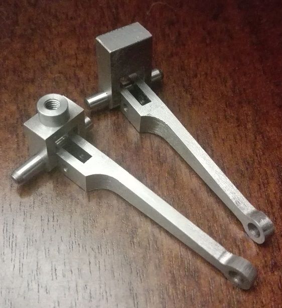
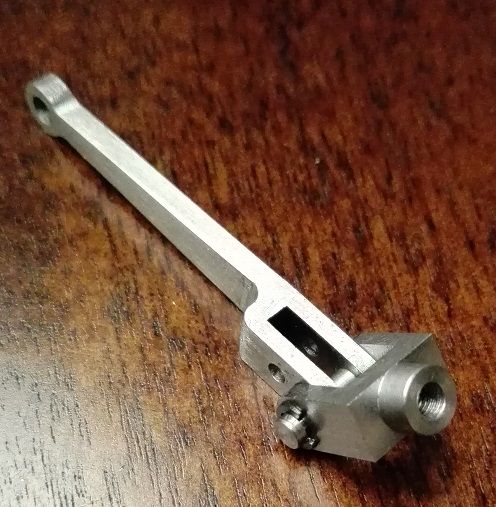
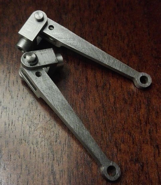
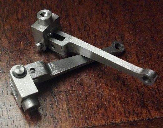
              Now for the valve spindle forks.

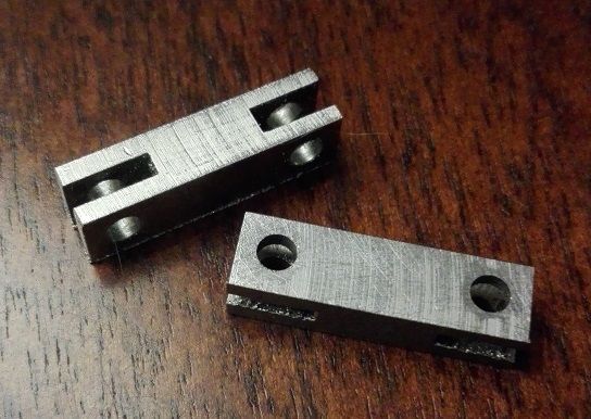
              These are machined from 6 mm steel plate.

              valve fork machining 001.jpg

              valve fork machining 002.jpg

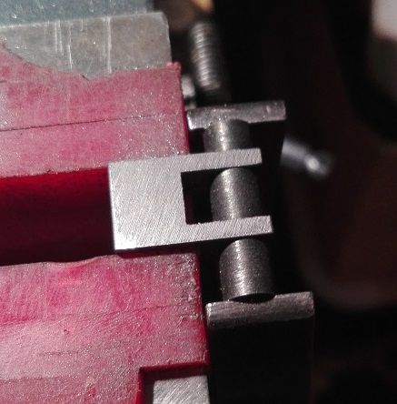
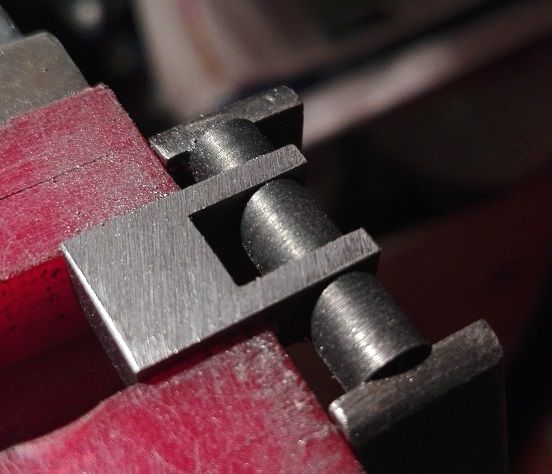
              Test fitting the combination levers.

              valve fork machining 003.jpg

              valve fork machining 004.jpg

              valve fork machining 005.jpg

              valve fork machining 006.jpg

              Above, the levers are tested in the forks with some 3 mm dowel pins.

              Next, file the radii on the fork ends and turn the spigot on the front of the fork and thread M3 for the valve spindle.

              #270768
              Ryan Norton
              Participant
                @ryannorton40317

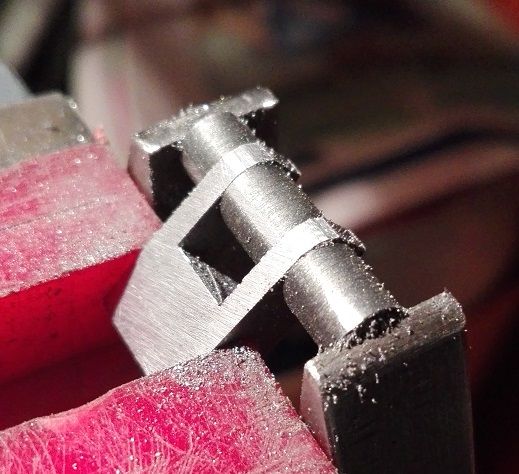
                The radii were filed using filing buttons held in place with the 3 mm dowel pin and a small engineers clamp.

                (The final thickness of the valve fork was also filed using the buttons as a guide- a bit off both sides)

                valve fork machining 007.jpg

                valve fork machining 008.jpg

                valve fork machining 009.jpg

                valve fork machining 010.jpg

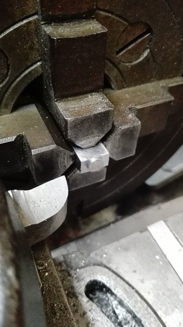
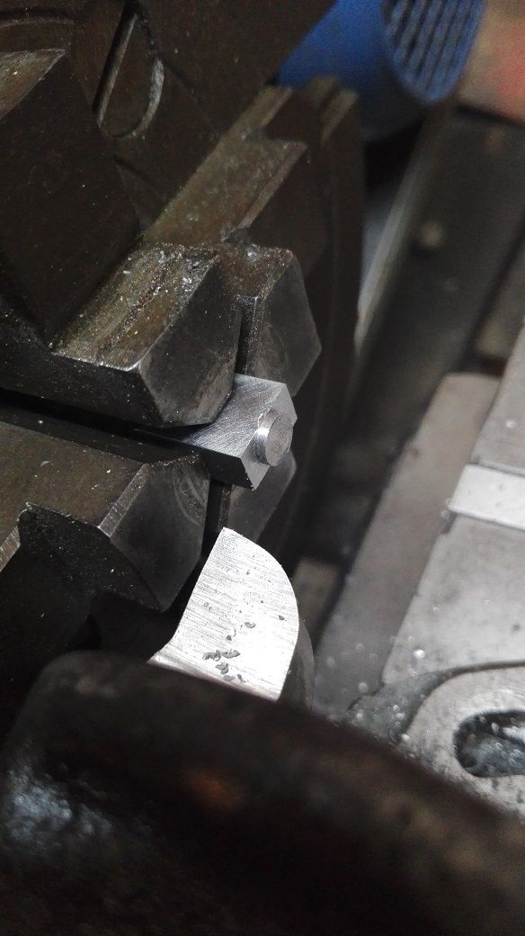
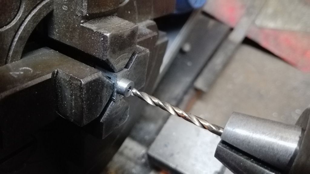
                The forks were then set-up in the four-jaw and faced to final length and then the spigot turned, drilled and tapped to M3 to suite the valve spindle.

                valve fork machining 011.jpg

                valve fork machining 012.jpg

                I used the excess to first do a test run on the sizes etc. then faced it off completely and turned the final spigot.

                valve fork machining 013.jpg

                valve fork machining 014.jpg

                valve fork machining 015.jpg

                valve fork machining 016.jpg

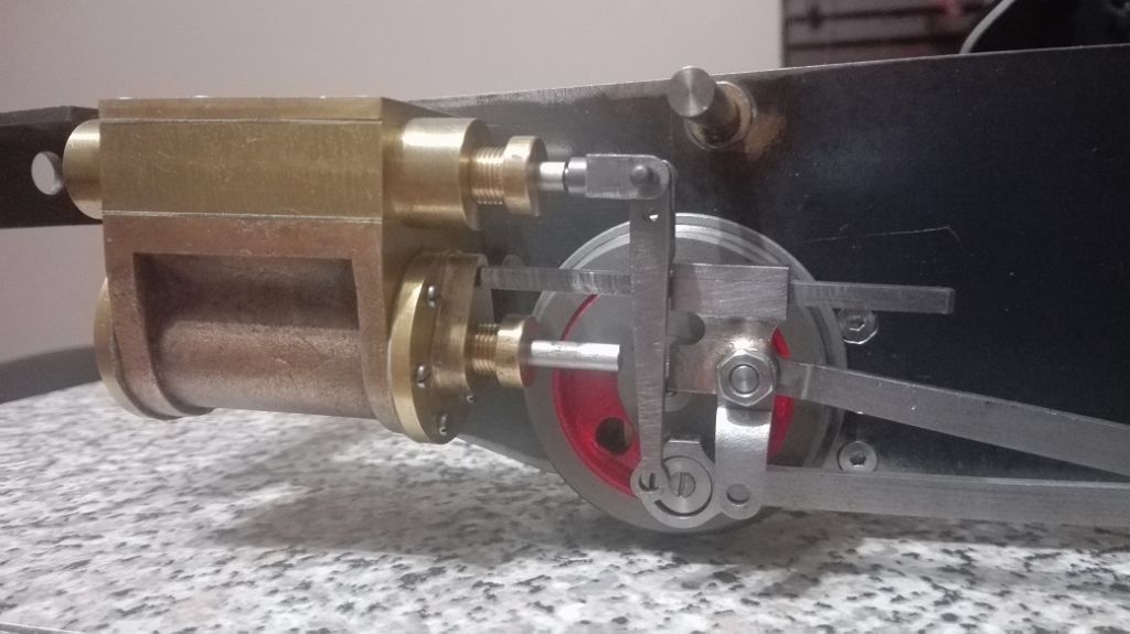
                Finally, test fit on the loco.

                valve fork machining 017.jpg

                #271508
                Ryan Norton
                Participant
                  @ryannorton40317

                  "a pin through the side of the return crank through the centre of the end of the crankpin is i think preferable to LBSC's arrangement. if you add a split and a locking bolt as well (as per the above pic) then this might help set the return crank and eccentric rod lengths but personally i would add a pin as well after this has been done.

                  it is probably obvious but a crankpin that has a return crank fitted should always be pinned to the wheel from behind (just in case!)"

                  Julian

                  I refer to the text above regarding the the crankpin that has a return crank fitted. Only now have I realised what you were getting at. At the time of writing, my wheels were already pressed onto the axles and the crank pins pressed into the wheels.

                  Is there any way to fix the crank pins to the wheels now? I would have liked to scotch key these pins if I had known earlier. The crank pins are pressed into the wheels pretty tight and I doubt they would move but I suppose there is always a chance.

                  Any thoughts?

                  Regards,

                  Ryan

                  #271532
                  julian atkins
                  Participant
                    @julianatkins58923

                    Hi Ryan,

                    It isnt possible to correct this now, so best to leave well alone if your crankpins are a tight fit into the wheels.

                    'Tight' = interference fit, with holes in the wheels reamed, and a decent finish on the turned down ends of the crankpins where they go into the wheels.

                    Cheers,

                    Julian

                    #271929
                    Ryan Norton
                    Participant
                      @ryannorton40317

                      Hi Julian

                      My tight fit is as you describe it above, hopefully it will be sufficient.

                      #271932
                      Ryan Norton
                      Participant
                        @ryannorton40317

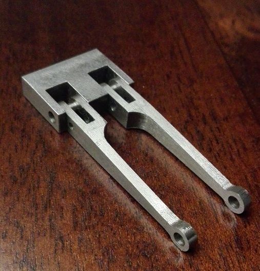
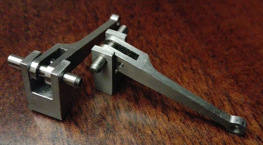
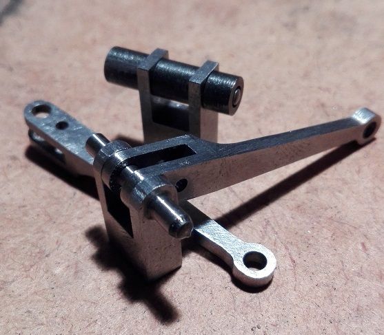
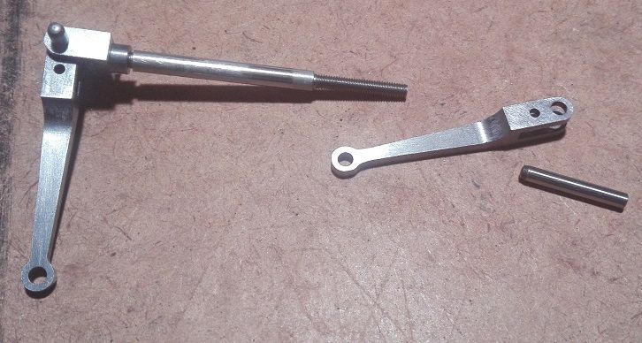
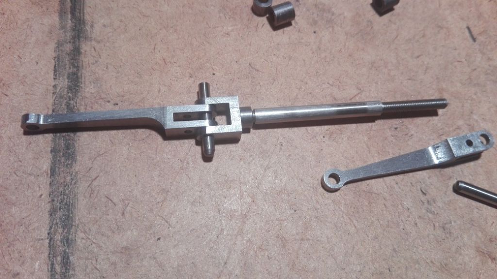
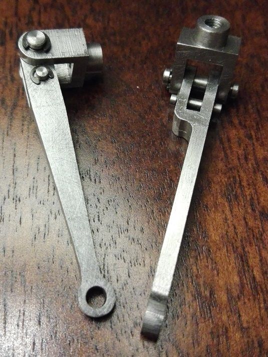
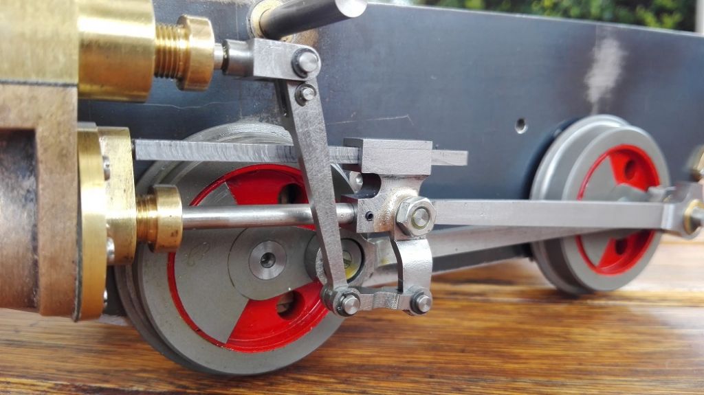
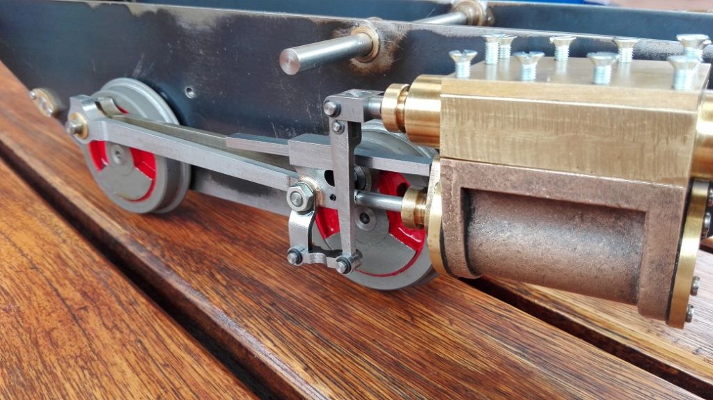
                        I have completed both valve forks now, but after fitting to the loco, there was a bit of a clearance issue with the cross head. It turns out, the radius I milled was too big so I had to file it slightly smaller. I also did the convex radius on each lever.

                        valve fork machining 018.jpg

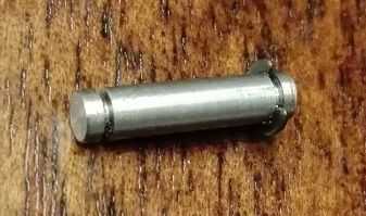
                        The pivot rods were also machined to size and the grooves for the e-clips cut.

                        valve fork machining 019.jpg

                        Here are the final levers, forks and pivots.

                        valve fork machining 020.jpg

                        valve fork machining 021.jpg

                        #273222
                        Ryan Norton
                        Participant
                          @ryannorton40317

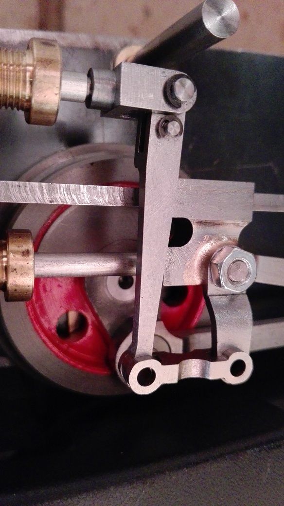
                          I have now completed the pivot pins for the combination lever-radius rod interface. These are 2 mm with 1.2 mm e-clips, tiny turning I tell you!

                          valve fork machining 022.jpg

                          valve fork machining 023.jpg

                          valve fork machining 024.jpg

                          #273233
                          SillyOldDuffer
                          Moderator
                            @sillyoldduffer
                            Posted by Ryan Norton on 04/12/2016 17:57:20:

                            I am fairly happy with my filing, possibly a couple of bits here and there to clean up.

                            You might be 'fairly happy' Ryan, I'd be over the moon if my filing was that good. Obviously I need a lot more practice!

                            Never mind, keep the pictures coming – they inspire me to try harder.

                            Cheers,

                            Dave

                            #275598
                            Ryan Norton
                            Participant
                              @ryannorton40317

                              Thanks Dave!

                              Happy New Year people!

                              Here are some photos of some of my productivity towards the end of last year.

                              union links 001.jpg

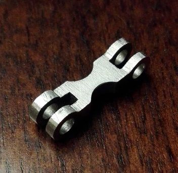
                              Embryo Union links

                              union links 002.jpg

                              union links 003.jpg

                              Almost finished union links

                              union links 004.jpg

                              union links 005.jpg

                              union links 006.jpg

                              My TICH

                              #276074
                              Ryan Norton
                              Participant
                                @ryannorton40317

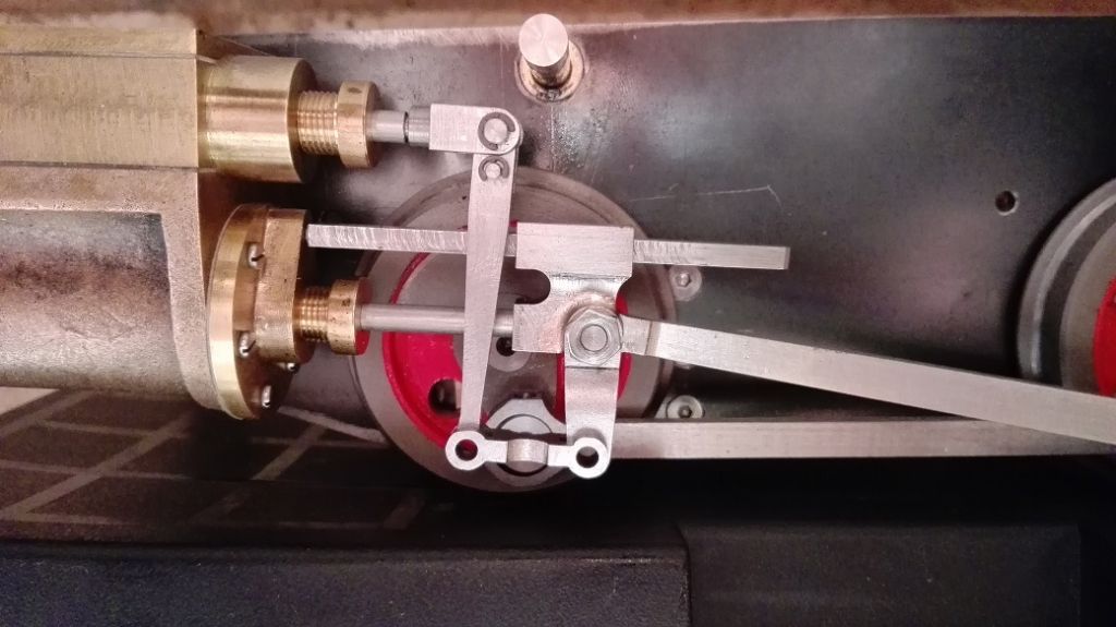
                                Here is another photograph with the union links and finished pins in situ.

                                union links 007.jpg

                                #276075
                                Jeff Dayman
                                Participant
                                  @jeffdayman43397

                                  Great work Ryan, well done! JD

                                  #278332
                                  Ryan Norton
                                  Participant
                                    @ryannorton40317

                                    Morning all

                                    Jeff, thanks.

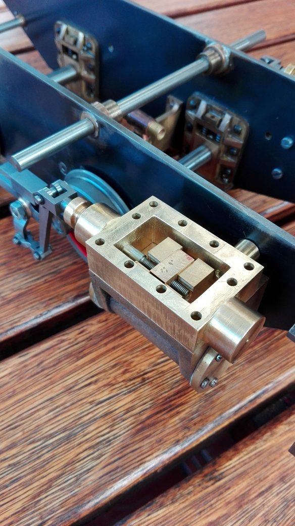
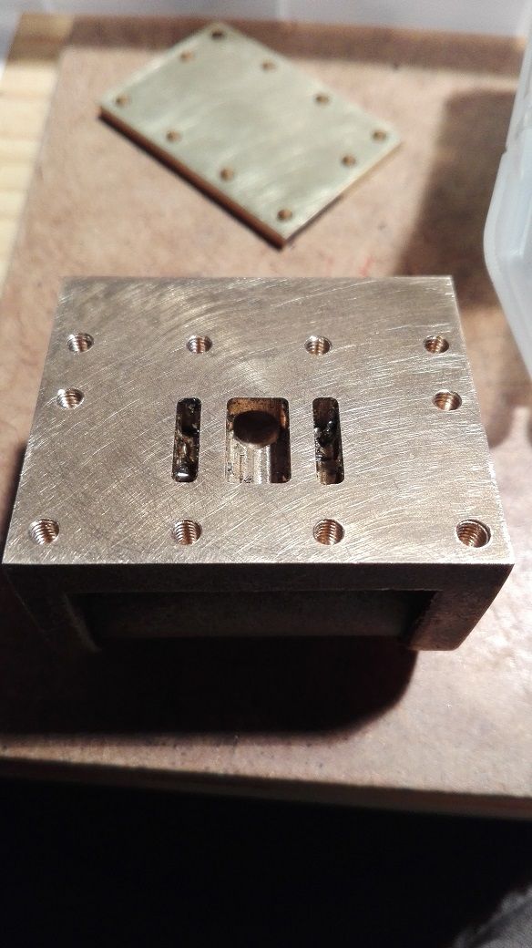
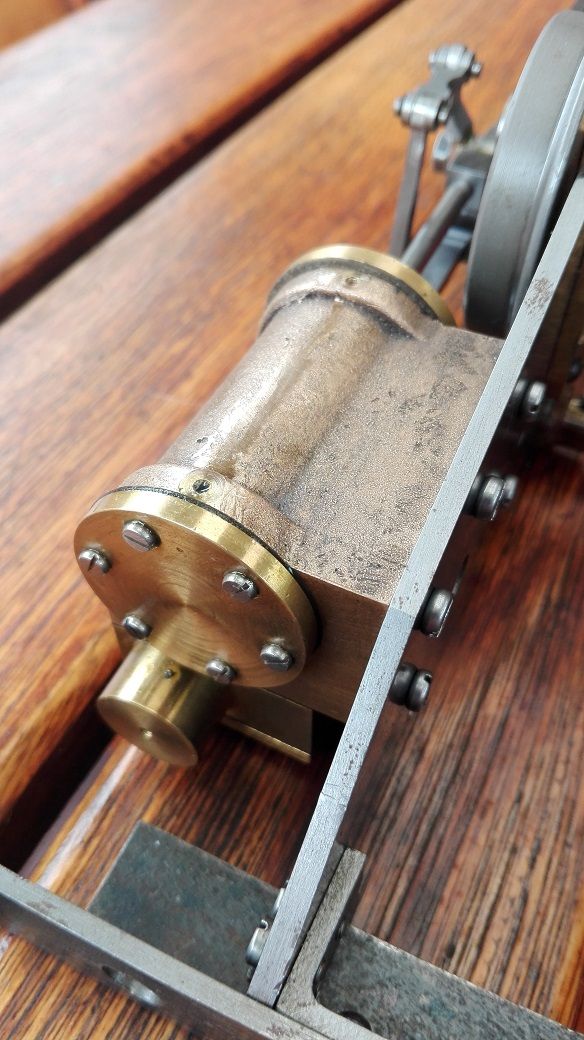
                                    I have been busy with a few small odd jobs recently on Tich. Finally I have done the RHS steam chest. All that is required is for me to complete the steam chest cover and drill the holes into the cylinder blocks, then both sides will be at the same stage.

                                    I also mentioned a while ago that I was not very happy with the current suspension springs that I had previously made, so with a couple of very difficult calculations and a bit of guess work, wink I have made some new springs.

                                    The method I had used previously was not as clean and repeatable as I would have liked and so I made some changes.

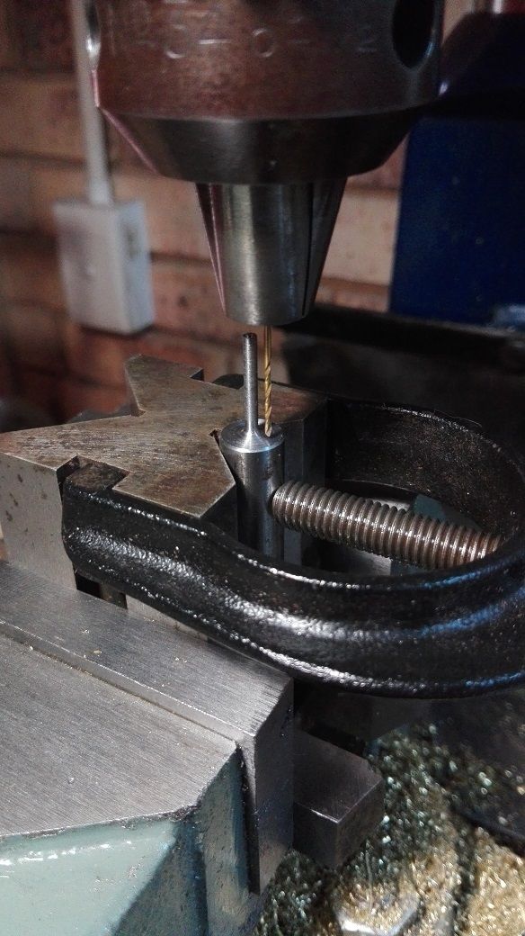
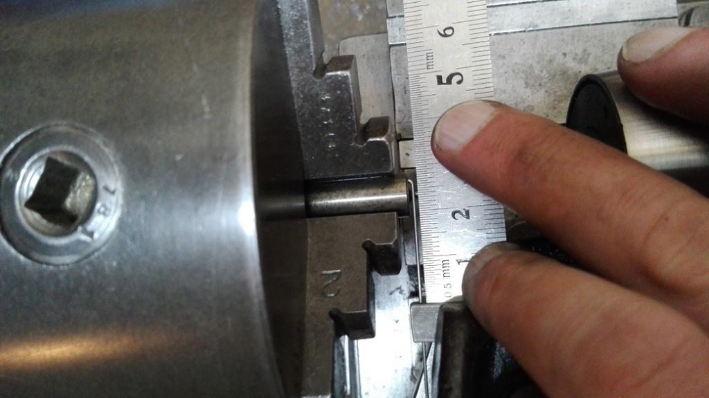
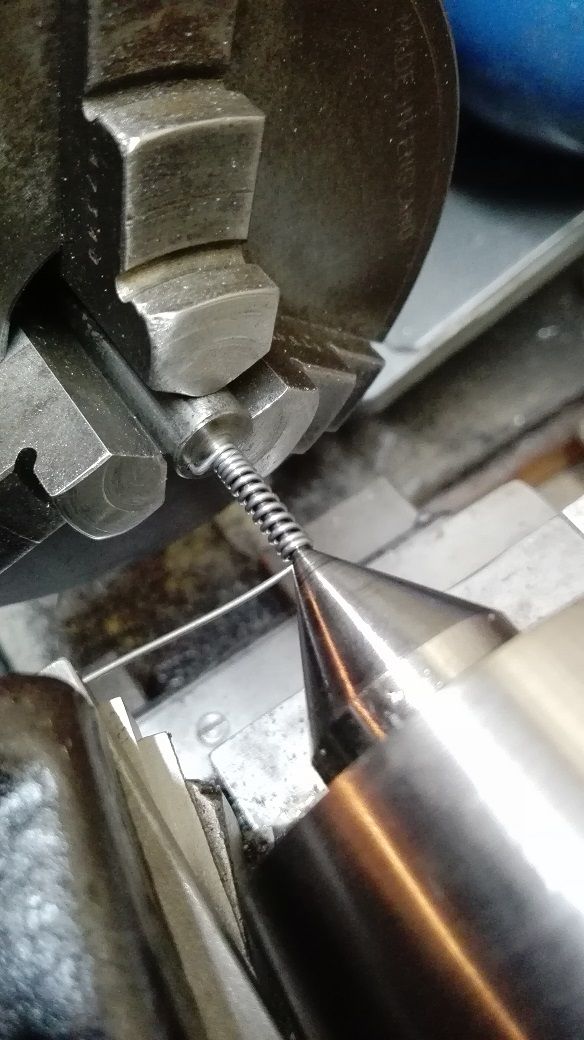
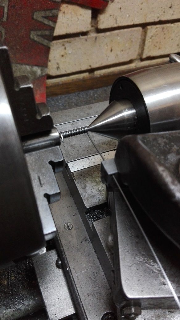
                                    Firstly I made a 2 mm mandrel from 10 mm silver steel onto which the wire would be wound. A 1 mm hole was drilled into the 10 mm rod, parallel with the thin part of the mandrel.

                                    springs 001.jpg

                                    This hole would allow for the wire to be kept in place when winding and would also allow for the finished spring to be slid off once finished.

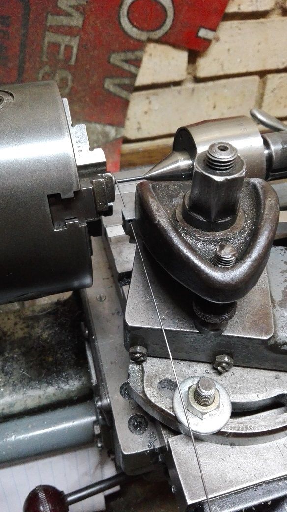
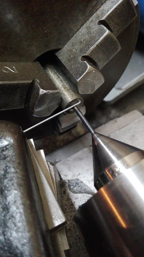
                                    The wire had a small 90 degree bend in it to go in the hole.

                                    springs 002.jpg

                                    springs 003.jpg

                                    springs 004.jpg

                                    The setup is pretty standard for spring winding as far as I know. In order for the process to be repeatable I noted the settings of the top slide, cross slide and lead screw dials as well as the orientation of the chuck jaws in relation to the starting point. The screw cutting gear train for 18 TPI was set up and 0.8 mm music wire was used.

                                    springs 005.jpg

                                    springs 006.jpg

                                    The silver steel mandrel was hardened and tempered as per standard practice for silver steel and the end was drilled for a running center to support the end.

                                    Once the springs were wound, they were ground to size with a couple of the redundant starting coils removed as well.

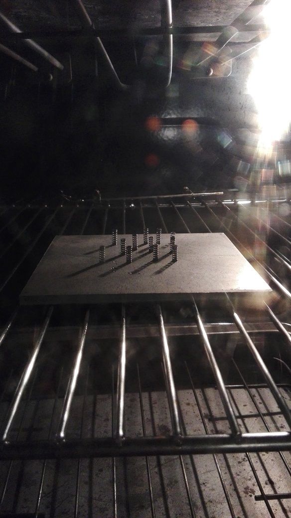
                                    I then placed the completed springs into the oven at 180 degrees Celsius for 30 minutes to remove any internal stresses caused by the bending process.

                                    springs 007.jpg

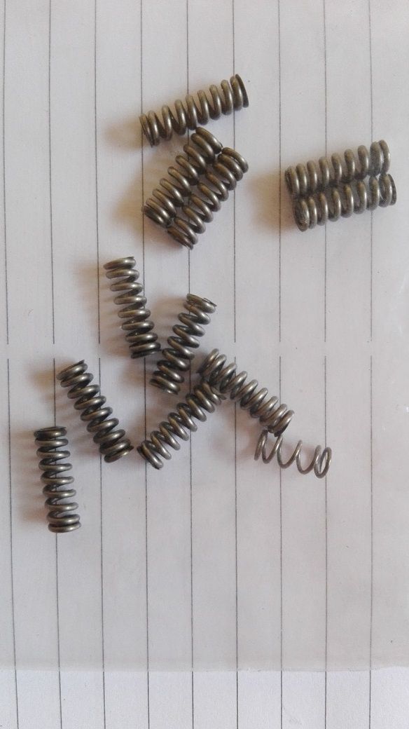
                                    Finally here is a look at the new springs versus one of my original springs which is clearly not correct for the job.

                                    springs 008.jpg

                                    #278424
                                    Steve Addy
                                    Participant
                                      @steveaddy35670

                                      Nice job Ryan. Keep up the good work.

                                      Steve

                                      #278459
                                      Neil Wyatt
                                      Moderator
                                        @neilwyatt

                                        yep, great work Ryan.

                                        Just to spoil your day, Reeves do suitable springs in little packets – but you made a great job of yours

                                        Neil

                                        #278537
                                        Ryan Norton
                                        Participant
                                          @ryannorton40317

                                          Thanks guys.

                                          Neil, with the current exchange rate and the shipping charges Reeves add to their South African packages, I could buy enough music wire to make all the springs I could ever want… so that was never an option unfortunately!
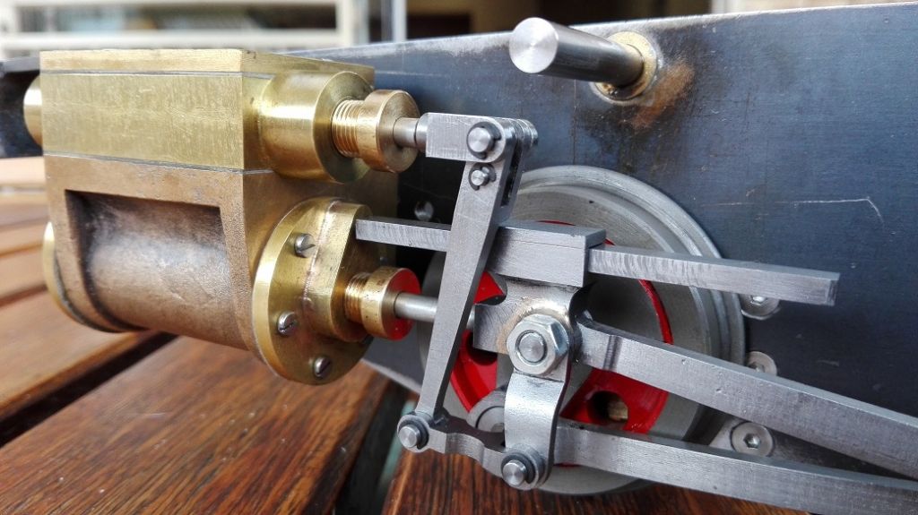
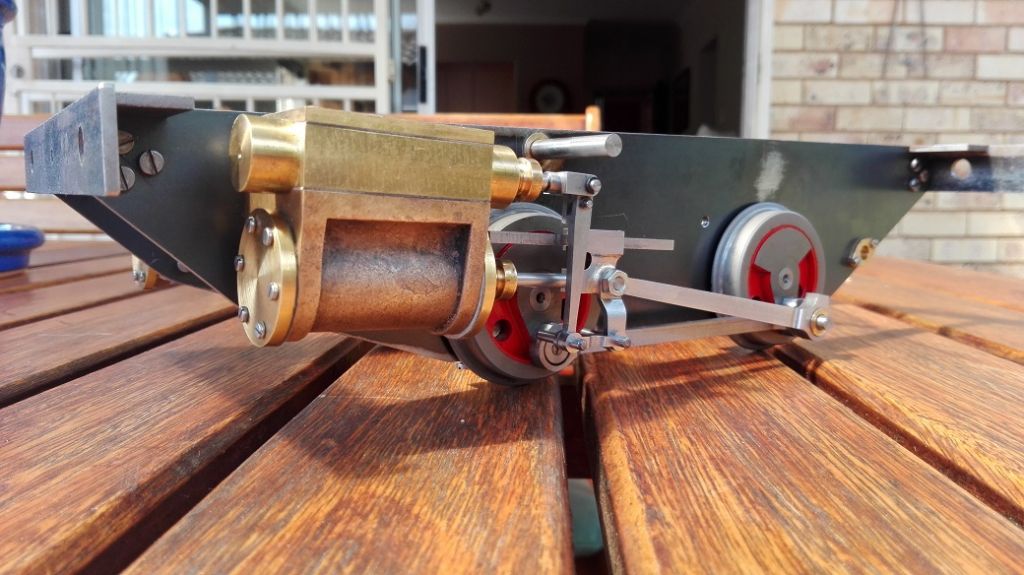
                                          Anyway, here are some photos of Tich with a new "spring in her step", as it were, as well as some others.

                                          s27.jpg

                                          s28.jpg

                                          springs 009.jpg

                                          mock up 023.jpg

                                          #281267
                                          Ryan Norton
                                          Participant
                                            @ryannorton40317

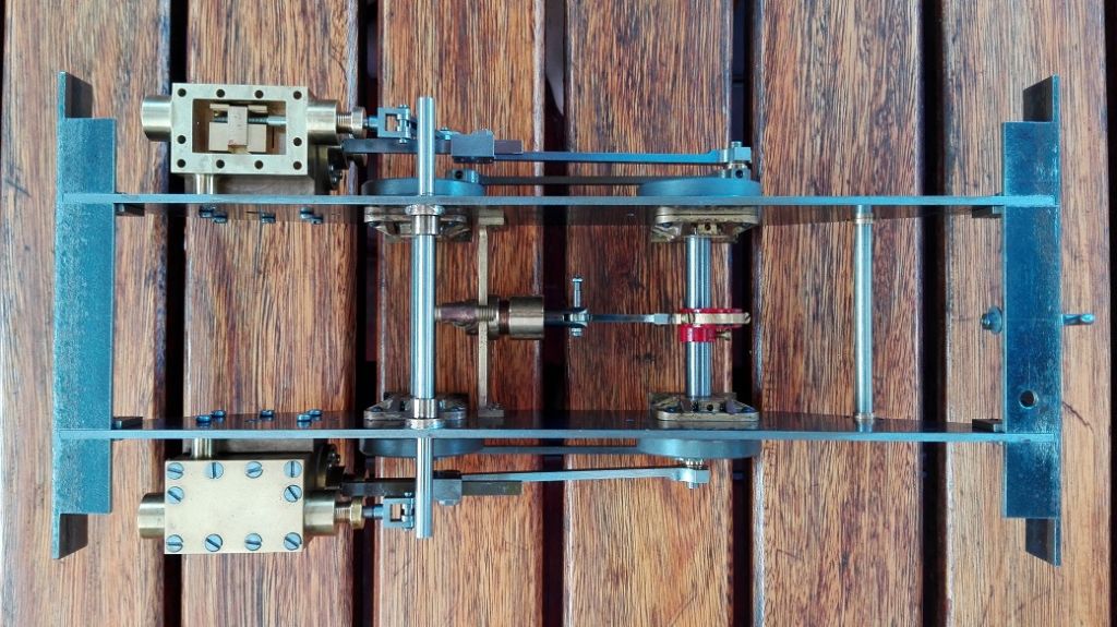
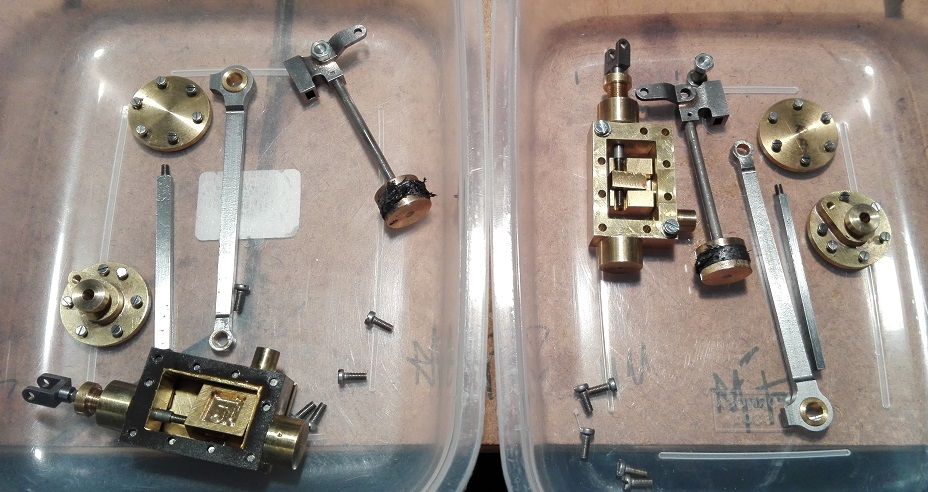
                                            I have been busy completing the RHS of TICH.

                                            Here are some photos

                                            44 rhs piston fitted.jpg

                                            45 drilled and tapped.jpg

                                            I have also drilled and tapped holes for drain cocks.

                                            46 drain cock holes.jpg

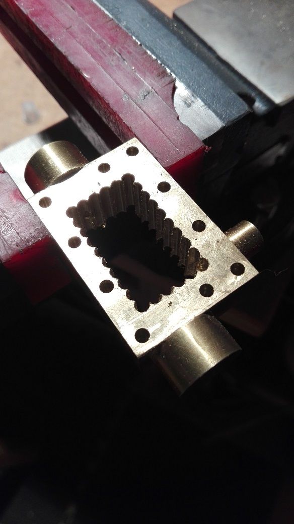
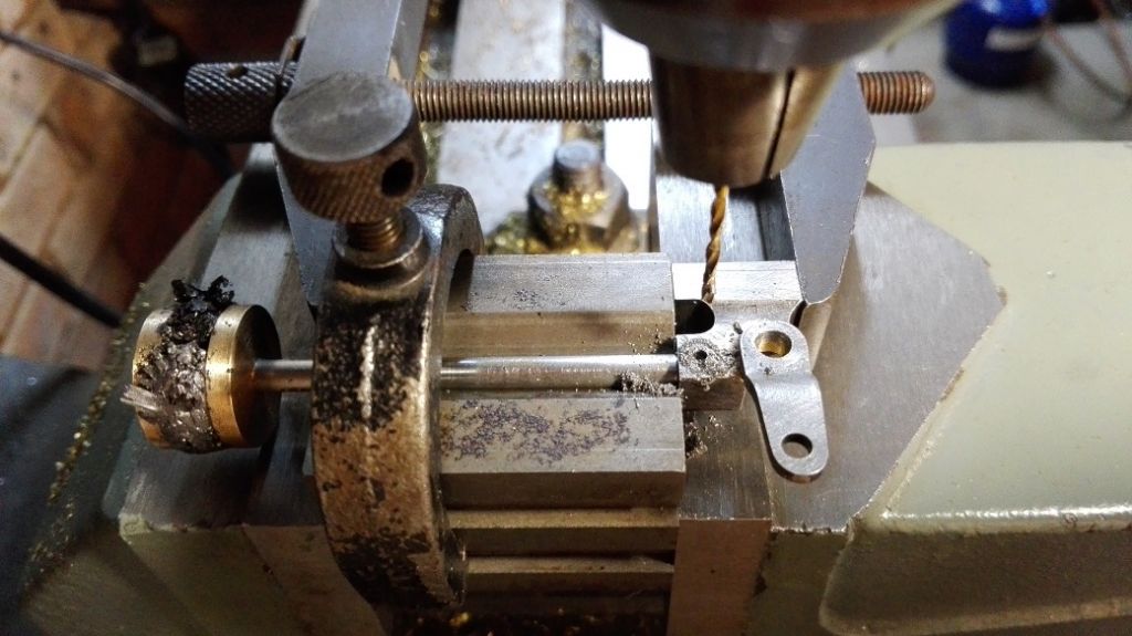
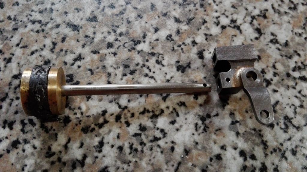
                                            The piston rods and cross heads were drilled as per the "Words and Music" but instead of a piece of spoke wire hammered in and filed flush, I have used spring pins.

                                            vassem 012.jpg

                                            piston drilling.jpg

                                            piston drilling 02jpg.jpg

                                            vassem 010.jpg

                                            vassem 011.jpg

                                            #281352
                                            Ryan Norton
                                            Participant
                                              @ryannorton40317

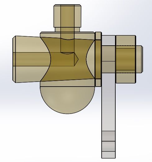
                                              I have done a quick design of a manual drain cock, based on some research and along the lines of what I like.

                                              I have come up with the following, keeping in mind I do not want something bulky:

                                              drain cock 001.jpg

                                              drain cock 002.jpg

                                              drain cock 003.jpg

                                              drain cock 004.jpg

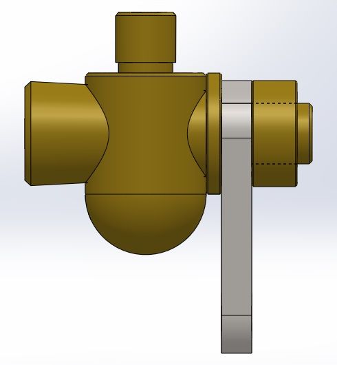
                                              The threaded parts are M2 and the steam hole is 1mm. There are minimal moving parts and only the need for one washer and nut. The cocks will be lever operated from the cab by means of levers or bicycle cable in a brass tube. Does anyone have any better ideas before I go ahead? I do not want auto drain cocks as I feel the manual ones are more "Romantic" if that makes sense…?

                                              #285540
                                              Ryan Norton
                                              Participant
                                                @ryannorton40317

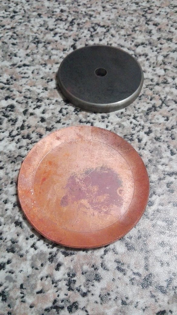
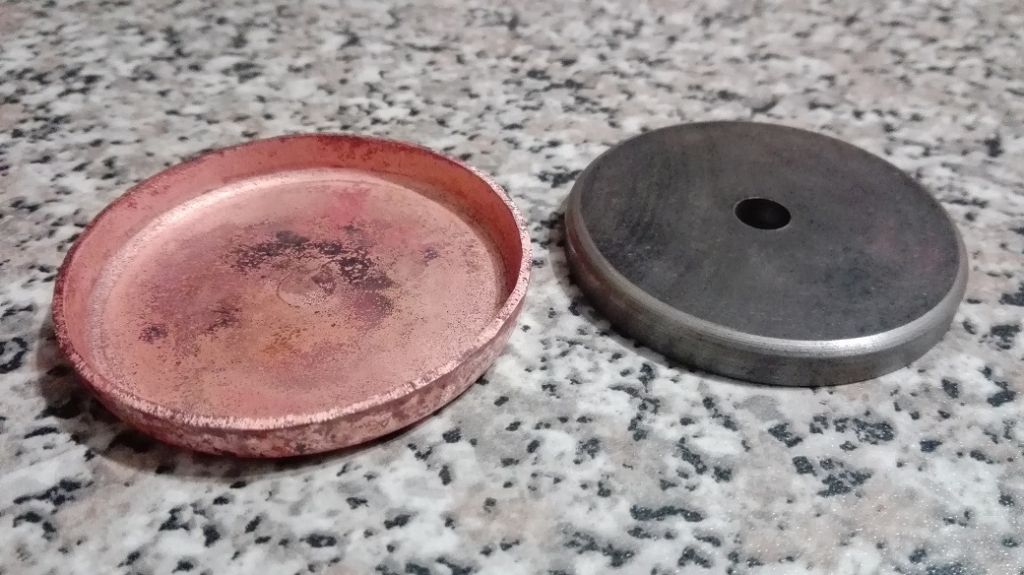
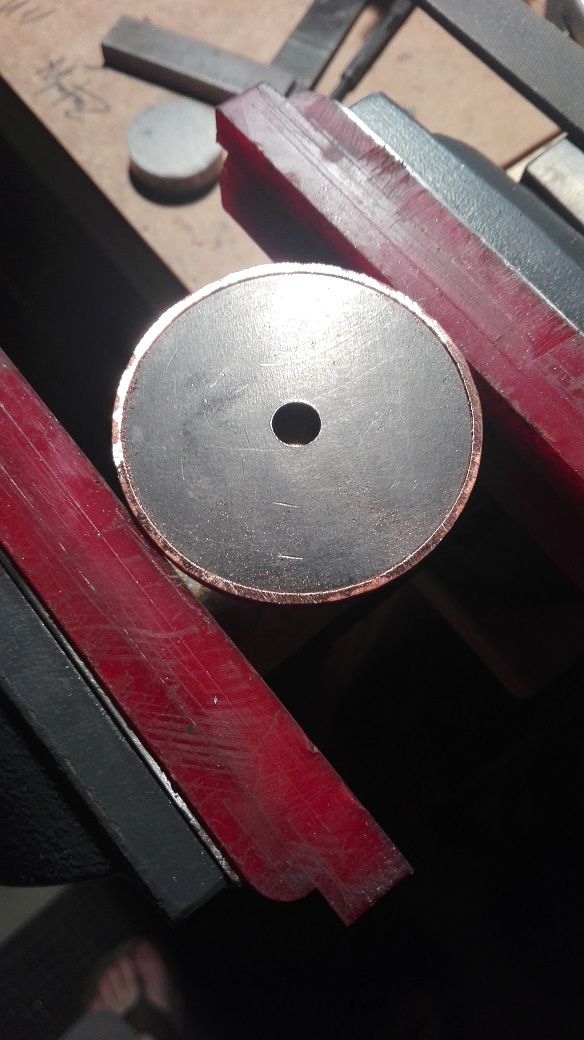
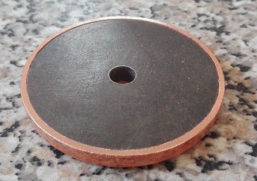
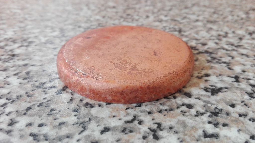
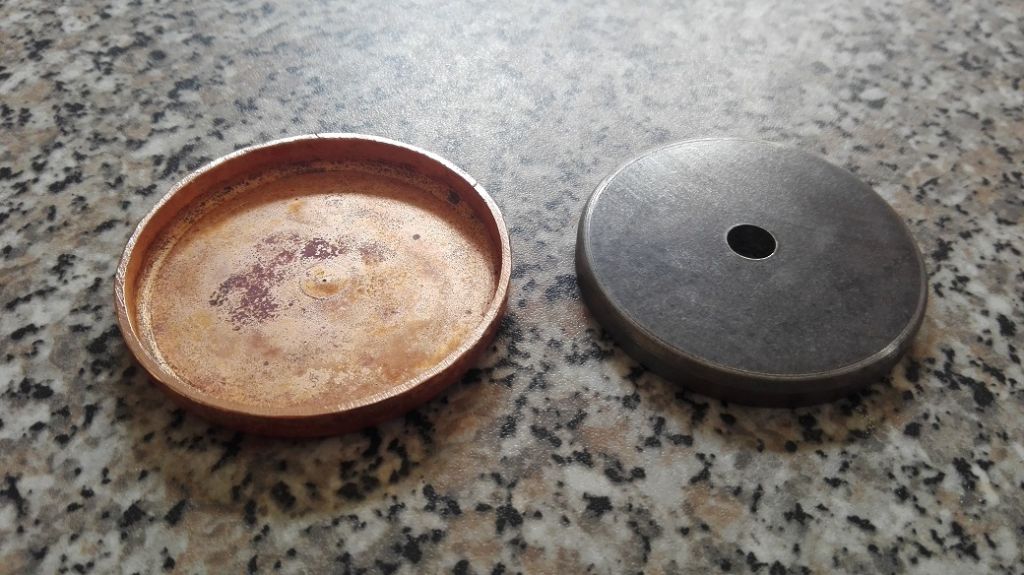
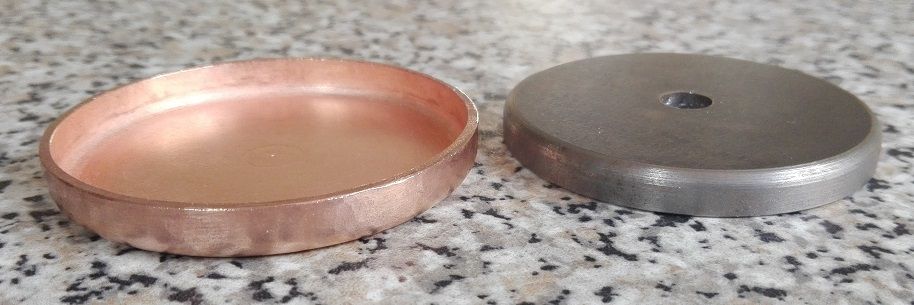
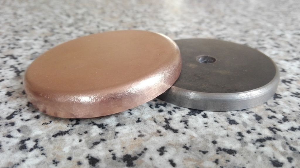
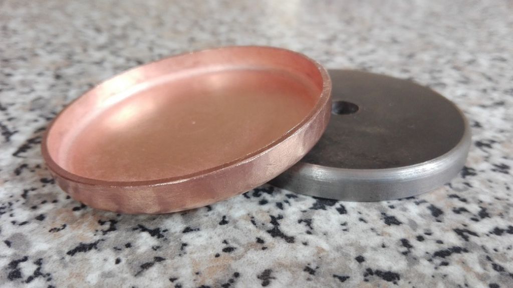
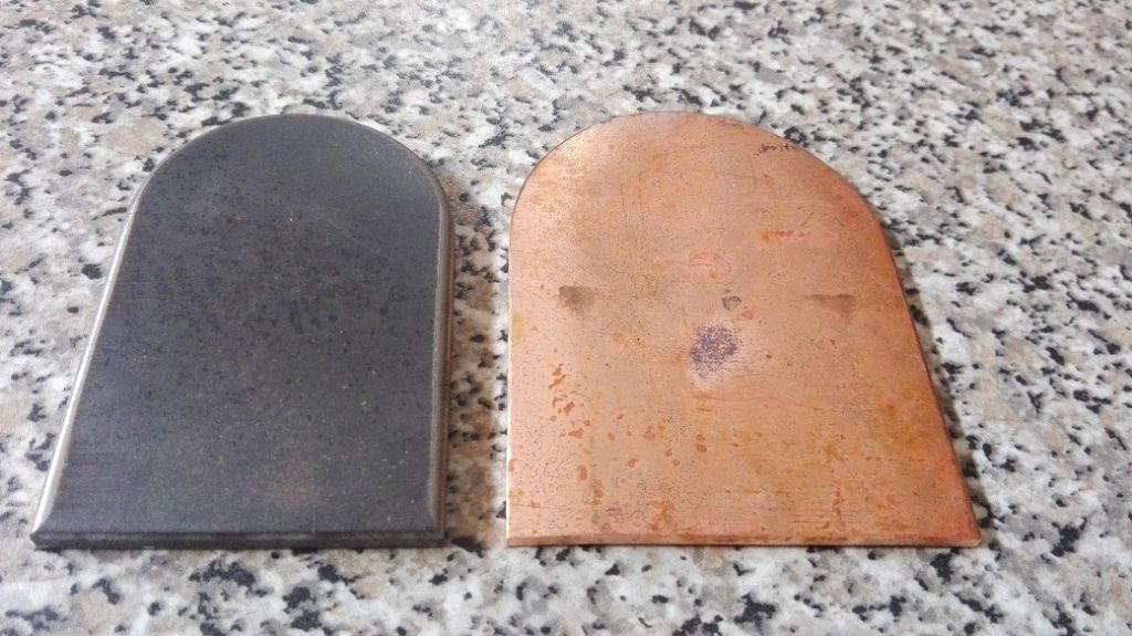
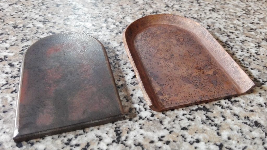
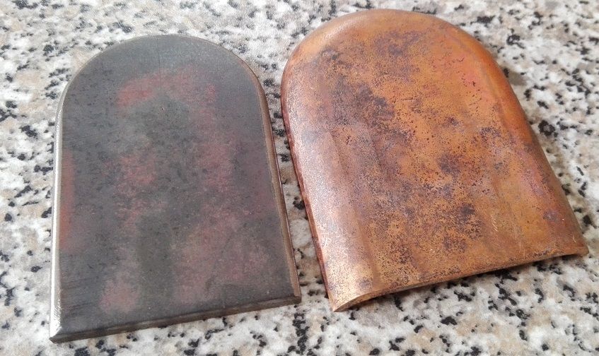
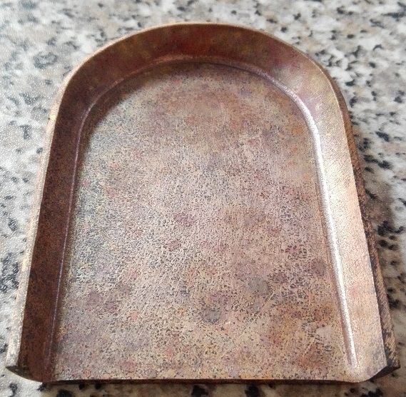
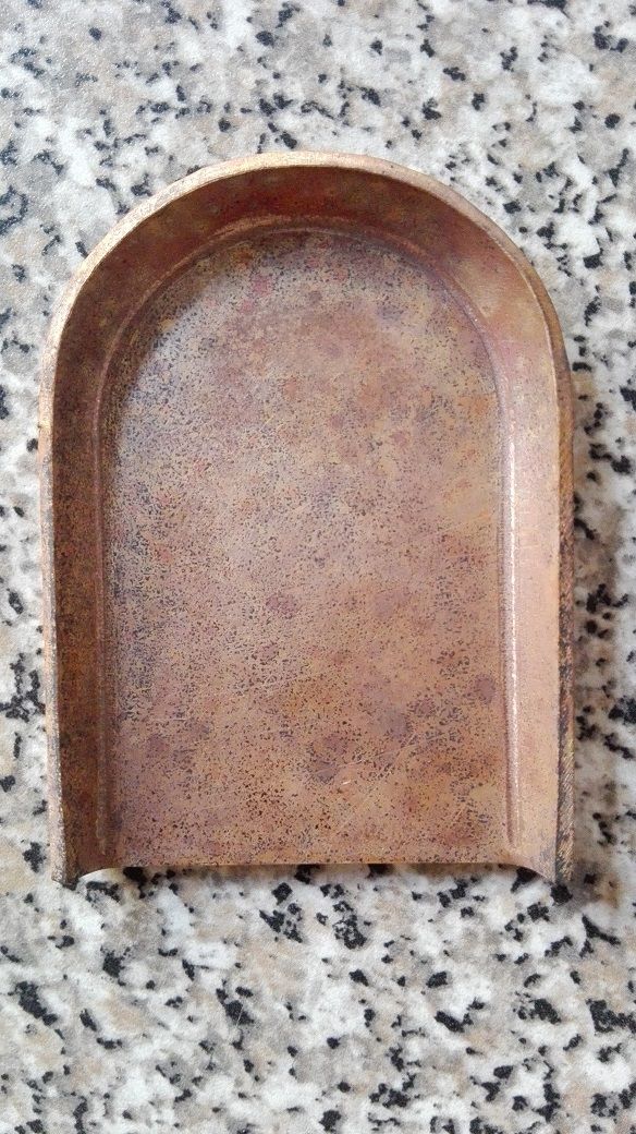
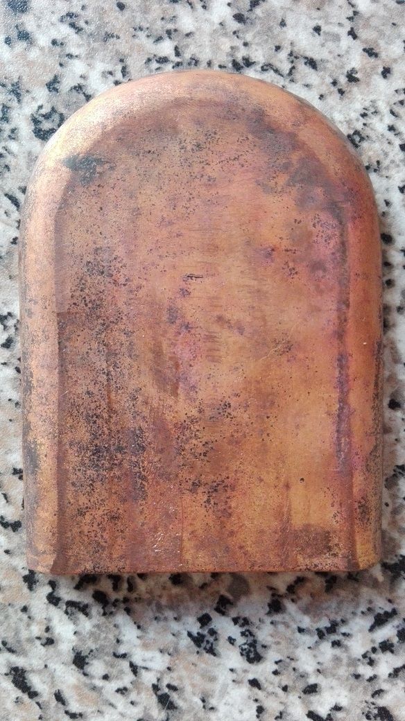
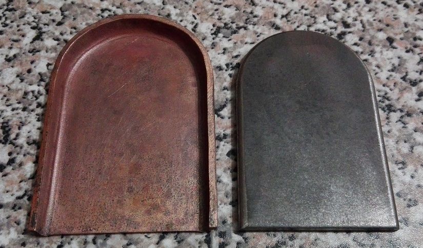
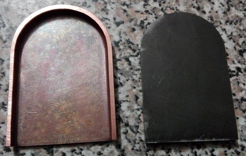
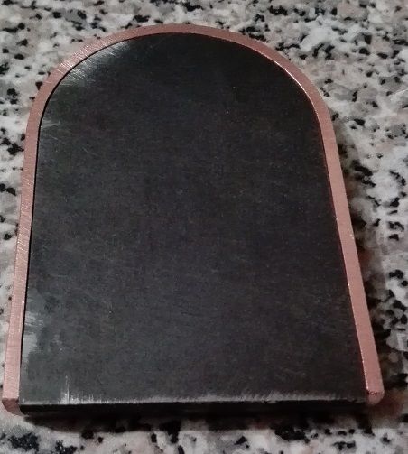
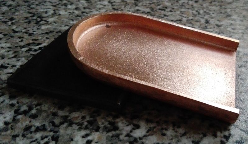
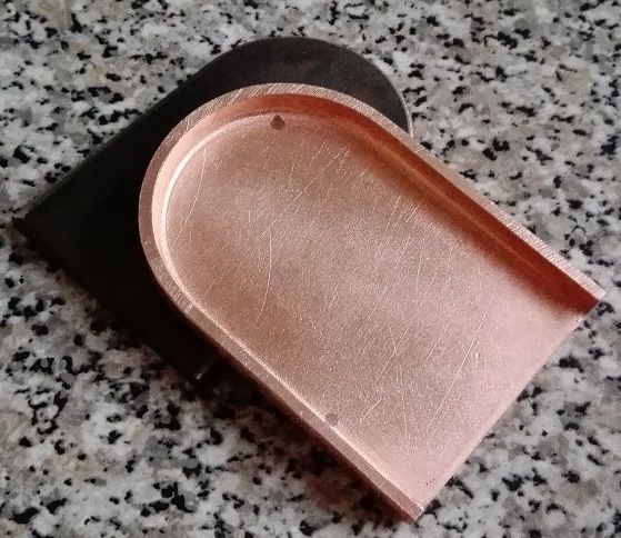
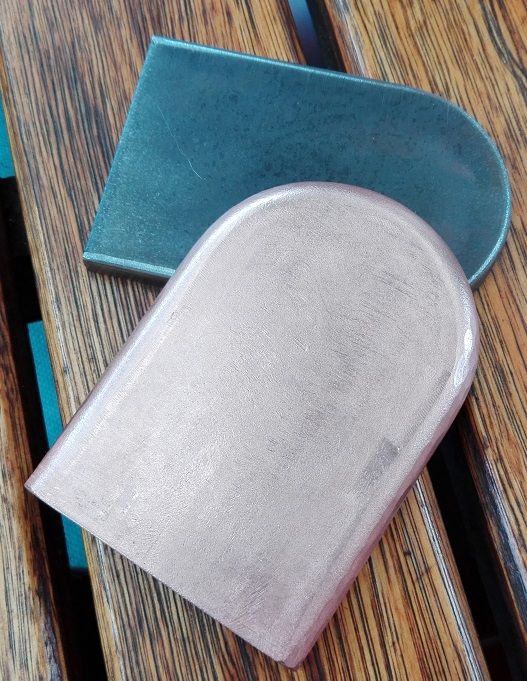
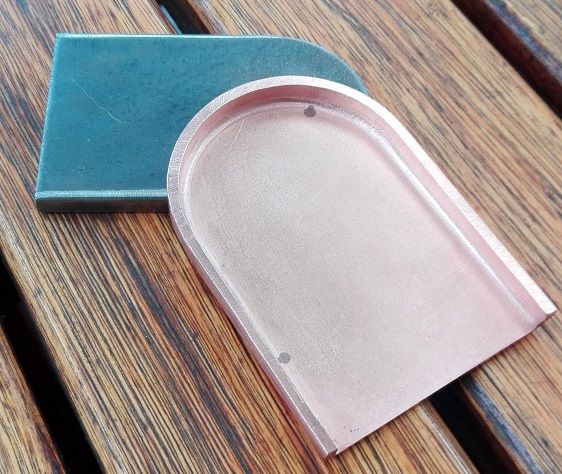
                                                I have been doing some more copper smithing. The smokebox tube plate and backhead are flanged and cleaned up.

                                                Here are some photos covering the process on both.

                                                smokebox tube plate 001.jpg

                                                smokebox tube plate 002.jpg

                                                smokebox tube plate 003.jpg

                                                smokebox tube plate 004.jpg

                                                smokebox tube plate 005.jpg

                                                smokebox tube plate 006.jpg

                                                smokebox tube plate 007.jpg

                                                smokebox tube plate 008.jpg

                                                smokebox tube plate 009.jpg

                                                smokebox tube plate 010.jpg

                                                smokebox tube plate 011.jpg

                                                and here is the backhead.

                                                backhead 008.jpg

                                                backhead 001.jpg

                                                backhead 002.jpg

                                                backhead 003.jpg

                                                backhead 004.jpg

                                                backhead 005.jpg

                                                backhead 006.jpg

                                                backhead 007.jpg

                                                backhead 009.jpg

                                                backhead 010.jpg

                                                backhead 011.jpg

                                                backhead 012.jpg

                                                backhead 013.jpg

                                                backhead 014.jpg

                                                backhead 015.jpg

                                                #285554
                                                Another JohnS
                                                Participant
                                                  @anotherjohns

                                                  Ryan, once again, beautiful work. I do like the spring making, like you, a "little packet from Reeves" is a large expense, due to international shipping.

                                                  My Tich is sitting on a bookshelf close by, waiting for the winter snows to melt – maybe 3 months from now it'll be out steaming again.

                                                  FWIW, when I made the pistons, I only had an old pre-1897 worn out lathe that worked at 1 speed, so the fit and finish was not great. One day, wheezing up hill at our track, I decided enough was enough, and took cylinders off and pistons out.

                                                  One piston had a whiff of graphite packing, the other was bare! Viton O rings fitted, and it has not looked back since. Something to keep in mind, but your workmanship far surpasses mine when I made those parts.

                                                  #285683
                                                  Ryan Norton
                                                  Participant
                                                    @ryannorton40317

                                                    Hi John, thanks!

                                                    Will keep what you have said in mind. Many people have commented on the use of graphite packing and the issues thereof. I am aware of the modern alternatives which have been pointed out and will see how she fairs with the graphite packing first, before i make any changes. I am using this whole build as a learning experience for myself.

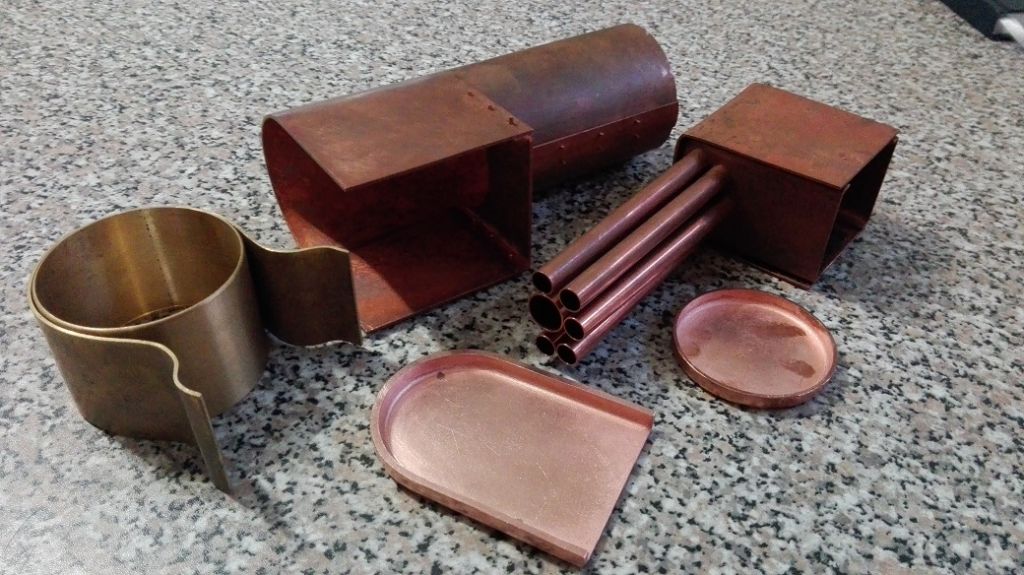
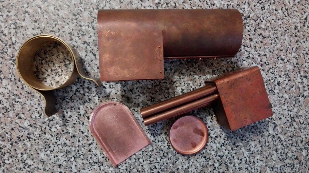
                                                    See pics below of the boiler bits thus far.

                                                    boiler parts 001.jpg

                                                    boiler parts 002.jpg

                                                    #285775
                                                    Neil Wyatt
                                                    Moderator
                                                      @neilwyatt

                                                      Very nice work, Ryan.

                                                      Neil

                                                    Viewing 25 posts - 201 through 225 (of 303 total)
                                                    • Please log in to reply to this topic. Registering is free and easy using the links on the menu at the top of this page.

                                                    Advert

                                                    Latest Replies

                                                    Viewing 25 topics - 1 through 25 (of 25 total)
                                                    Viewing 25 topics - 1 through 25 (of 25 total)

                                                    View full reply list.

                                                    Advert

                                                    Newsletter Sign-up