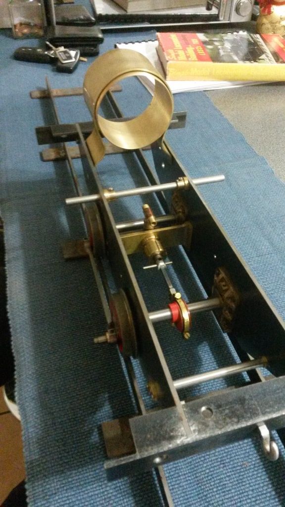
3 1/2 inch small boilered TICH

Advert

3 1/2 inch small boilered TICH

Home Forums Work In Progress and completed items 3 1/2 inch small boilered TICH

Viewing 25 posts - 51 through 75 (of 303 total)
  • Author
    Posts
  • #147243
    David Haynes
    Participant
      @davidhaynes53962

      Hi All,

      Stewart, there are various things that may effect binding of wheels, to some extent or another. Working by a process of elimination to identify the fault applies to all the construction process, if you have any faults that is. Assuming that the chassis rolls happily down a piece of inclined track before the coupling rods are fitted, then the following may be a cause: –

      – Coupling rod centres not the same length as the wheel centres (the wheel centres may differ from as the drawn dimension and between left and right side of the loco);

      – Wheels not quartered correctly;

      – Crank pins not perpendicular to the plane of the coupling rods;

      – Coupling rod bushes not bored perpendicular to plane of coupling rods.

      All the best,

      Dave

      Edited By David Haynes on 16/03/2014 21:50:21

      Edited By David Haynes on 16/03/2014 21:51:33

      Advert
      #147315
      julian atkins
      Participant
        @julianatkins58923

        hi ryan,

        you are making a super job on your TICH! you ought to have attempted something more ambitious and larger by the skill you have shown! i am particularly impressed by the fabrication of parts ( im the same to save on castings) and the super finish on the cylinders.

        very well done!

        cheers,

        julian

        #147517
        Ryan Norton
        Participant
          @ryannorton40317

          David, thanks for the super explanation! I really appreciate it when people take the time to explain the intricacies of model engineering!

          Thanks Julian, much appreciated.

          #148999
          Stewart Paterson
          Participant
            @stewartpaterson78346

            David,

            Thanks for your response / help on curing binding rods.

            I did more or less as you advised stripped down to components and checked each, I think all the possible causes you mentioned were present to some degree and all combined they resulted in binding.

            The worst deviation the rod bushes appeared to be not square to the plane of the rod. I fact the rods bowed when milled to reduce the web thickness as per drawing. This was obvious when I put round bars through each eye and saw they were not parallel. A check of rod with a straightedge confirmed the bowing, this was straightened by hand and dramatically improved freedom.

            My next question – is pinning the piston rod to the crosshead the best / only way to make this connection on such a small model?

            Stewart Paterson

            #155634
            Ryan Norton
            Participant
              @ryannorton40317

              Hi again finally!

              I just thought i would post this pic of the embryo smokebox as it sits at present. I am currently working on the rear cylinder covers. I had an issue with the pin drill i made and as such need to make a new one. Hopefully I will complete this task on the weekend and have some photos on Monday.

              I have also tapped the hole for the brake column.

              Below is my Tich on the kitchen table, where all good locomotives belong….smile p

              30 embryo smokebox.jpg

              #156426
              MK
              Participant
                @mk72051

                Looking great Ryan

                Where did you get hold of that brass tube?

                #156643
                Ryan Norton
                Participant
                  @ryannorton40317

                  HI MK

                  I actually fabricated the brass tube…

                  I found a smaller diameter piece at a scrap yard, looked like an old hydraulic cylinder or something.

                  I then split the tube length ways with a hacksaw, annealed the brass, opened up the tube and inserted a segment into the tube to make it bigger. I silversoldered this together and then machined the outer and inner surfaces to suit the dimensions given in the words and music.

                  The original tube wall thickness was 2.5mm so there was enough to machine off.

                  You cant see it in this photo but I actually distorted the tube when forming the outer smokebox wrapper. So my perfectly machined smokebox is not as perfect as I want it but it will never be seen so I am leaving it for now.

                  Anyway.. more on that later.

                  #166420
                  Graham Powell 1
                  Participant
                    @grahampowell1

                    Following this with great interest. I have started to build one mainly to try and improve my engineering skills. I am following the words and music in the book.

                    What is the best way to drill the axleboxes to take the axles?. I have heard horror stories about drilling large holes in gunmetal.

                    rgds

                    Graham Powell

                    #166490
                    julian atkins
                    Participant
                      @julianatkins58923

                      hi graham,

                      centre and drill with sharp new drills with the edges backed off for gunmetal, then once big enough for a boring tool i bore to just under size then ream, or bore to size.

                      cheers,

                      julian

                      #166506
                      Graham Powell 1
                      Participant
                        @grahampowell1

                        Hi Julian

                        Many thanks for the kind reply. I have never done any boring so it will be good practice for me. LBSC advocates clamping the boxes together and drilling a hole through both. This then needs enlarging to a size suitable for a 3/8 reamer. I like the sound of your method but I am assuming that the boxes will need to be set up in a four jaw chuck. Doing them that way, will accuracy be maintained?. I am assuming just drilling the holes in a pillar drill is not a good idea!. Apologies if I sound like a complete duffer but I am new to this though not new to modelling trains.

                        rgds

                        Graham Powell

                        #166583
                        julian atkins
                        Participant
                          @julianatkins58923

                          hi graham,

                          ive always bored my axleboxes in the 4 jaw, but have milled the slots for the horncheeks first then adding packing pieces in the slots when putting in the 4-jaw. if you slacken off the same 2 jaws all the axleboxes should be bored (and then reamed) to the same setting. for the last 25 years ive only made split axleboxes, but this is probably a refinement you dont need to bother with for Tich and stick to the LBSC's drawings and 'words and music'!

                          cheers,

                          julian

                          #166590
                          Ryan Norton
                          Participant
                            @ryannorton40317

                            Graham

                            As Juian has said, doing the axleboxes in the four jaw is probably the easiest. If you follow the "Words and music" you will find that LBSC managed to do things very quickly with the minimum amount of effort and yet still yeilded precise results.

                            If you look at my photos, I milled the bar used for the axleboxes on both sides to create the flange. this bar was then cut into four pieces and finished to size. Two of the embryo axleboxes were then placed together with the unflanged ends touching. Two pieces of scrap of the correct size were then inserted between the flanges as Julian describes above and the whole magoby placed into the four jaw.

                            It is important to note here that placing all these bits into the four jaw requires a bit of finess and that you need to make sure that the two faces of the axleboxes are definately touching each other.

                            The rest really is very easy. Using a sharp drill with the edges backed off, drill through, after using a center drill. I used a 9.9mm final drill and then reamed the holes to 10mm as I only have 10mm silver steel stock available.

                            Regards,

                            Ryan

                            #166597
                            Graham Powell 1
                            Participant
                              @grahampowell1

                              Hello Ryan,

                              Its all your fault!. Being so impressed with your write up and pictures I decided to have a go myself. I have a fairly well equipped little workshop but 3.5 inch engines will be about the limit if I am to get in there as well. I have the castings for the wheels, hornblocks and axleboxes. ( Very prompt service from GLR Kennions). So far I have made the frames and yesterday made the little clamp to hold the hornblocks for milling. Today I am hoping to cut the buffer beams. I am following the LBSC book as far as possible with help and advice from chaps on the Forum. Later on in the book, LBSC advocates drilling the steam ports by hand. This sounds like a recipe for disaster in my opinion. How did you do yours? I am not too worried about having a working locomotive . I am just hoping to get a chassis that will run on air and if that works obtain a boiler. I shall probably get Helen at Western Steam to make they boiler as they are only just down the road. Keep the pictures and write up coming. I am sure I am not the only one inspired by your efforts.

                              rgds

                              Graham Powell

                              #166600
                              Ryan Norton
                              Participant
                                @ryannorton40317

                                Thats right blame me. As long as more people build this little beaut im alright with it.

                                Im glad you're inspired!

                                LBSC talks of drilling the ports by hand, probably using an old hand drill, which is slow and therefore easy to control.

                                I drilled my ports in the drill press with the vice clamped to the press table at the required angle. This operation is difficult to set up as you need to line up the drill on the outside of the cylinder to see if the alignment is correct.

                                I drew the placement of the ports in pencil on the side and used this for alignment.

                                Be very careful of the drill pulling into the cylinder and going straight through all the ports, I have had this happen before and it is not easy to fix.

                                If a milling machine is available to you, it would be esier to drill the steam holes. Give me a shout when you get closer to this operation and we can chat.

                                Some advice on the buffer beams, LBSC indicates that the rivets should have the heads on the inside and the outsides filed flush, which is what I've done. In hind site I would have preferred seeing the rivet heads on the outside of the beams next to the buffers.

                                Just a thought.

                                Good luck with the rest of your work!

                                #166608
                                Graham Powell 1
                                Participant
                                  @grahampowell1

                                  Hi Ryan,

                                  Thanks for that. I am still at that very early stage but I will be picking your brains as I go along. I'll ask about the cylinders when I get to them . Yours are beautifully finished. Certainly drilling the ports seems to be very tricky but I will cross that bridge when I get to it.

                                  All the best

                                  rgds

                                  Graham Powell

                                  #166611
                                  David Haynes
                                  Participant
                                    @davidhaynes53962

                                    Graham,

                                    Take great care with the ports however you do them, I did mine on a vertical slide in the lathe and was not satisfied with the result, I wish I had the milling machine I have now when I did them. You might find when drilling any 'small delicate/critical hole' that if you start one or even two drill sizes down and gradually work up to size, this can give some chance to recover a mistake. Despite this and what seems like a high amount of errors in my Tich construction, along with my own doubts and expecting it to fail, the chassis happily burst into life with about 20 PSI. A tribute to the robustness of Walchaerts' valve gear and the LBSC design. On the subject of exposed rivet heads in buffer beams, it has been discussed here or elsewhere; they look nice but are a pain to paint and in prototypical practice, many are hidded anyway!

                                    Dave

                                    #166624
                                    Graham Powell 1
                                    Participant
                                      @grahampowell1

                                      Hi David,

                                      Why is using a milling machine better?. Is it a question of cutting speed or slower rate of feed. I do have a small milling machine which I think the tailstock chuck on the lathe will fit. Not got that far yet still on the buffer beams

                                      ( one of which I cut to the wrong length – definitely a case of measure twice, cut once.

                                      rgds

                                      Graham Powell

                                      #166636
                                      David Haynes
                                      Participant
                                        @davidhaynes53962

                                        A lathe with a vertical slide is an approximation of a milling machine but may not be as rigid a set up as a milling machine. The vertical slide introduces another element into the path of fixing the work piece to the machine bed. As many more experienced people here than me will tell you, if you have a high degree of confidence in the accuracy of your lathe operation and vertical slide and take things slowly, it will be fine. A poor milling machine set up could be the worse option. Also, it is not recommended to use ordinary 3 jaw chucks for holding milling cutters, they can screw out during use and the chucks are not designed for lateral milling forces. I personally find I have more control and precision for some jobs with the mill.

                                        Dave

                                        #166645
                                        Graham Powell 1
                                        Participant
                                          @grahampowell1

                                          Hi David,

                                          Thanks for that. When I get to that bit, I will take it all on board before deciding what to do. When facing off the cylinder castings etc what do you recommend in the way of tooling and lathe speed etc. Ryan has a wonderful finish on the components he has done. Still that is a little way at the moment.

                                          Bye for now

                                          rgs

                                          Graham Powell

                                          #166736
                                          Ryan Norton
                                          Participant
                                            @ryannorton40317

                                            Hi Graham

                                            When facing the cylinder castings, tooling and speed is something you will need to work out through trial and error. LBSC gives an indication that a round nose tool placed perpendicular to the cylinder face should be used. Obviously, being a rather large piece of metal, your speed should be on the lower end and make sure include a counter weight on the face plate or your lathe will wobble!

                                            The finish of your tool will also make a huge difference here and therefore trying different speeds with your tool at slightly different angles may help with a better finish.

                                            I placed the finished cylinders onto a piece of emery paper on a piece of float glass and lightly rubbed them with a circular movement to obtain the finish you see in the photos. This finish is often used on wobbler cylinder faces to ensure an almost steam tight fit when oil is introduced.

                                            I thought it would be appropriate here as we need a similar fit with the valve.

                                            Hope this helps.

                                            #166741
                                            Graham Powell 1
                                            Participant
                                              @grahampowell1

                                              Hi Ryan

                                              Thanks for the sound advice. it does appear that although LBSC covered the building in some detail, you need to be able to work out some things for yourself. Not a bad thing in reality. I found it a good way to learn how to do things in the past. I normally work in a much smaller scale ( Gauge 0) and I use the emery cloth on a piece of plate glass to get a nice smooth finish on the backs of the wheels.

                                              regards

                                              Graham

                                              #168112
                                              Graham Powell 1
                                              Participant
                                                @grahampowell1

                                                Stupid question time!. In his book LBSC says fairly often "drill 1/4 inch and thread 1/4 x 40 tpi " as an example.
                                                Surely when tapping holes you need to drill a tapping size hole or have I got that wrong!. Seems a bit vague to me.

                                                rgds

                                                Graham Powell

                                                #168122
                                                IanT
                                                Participant
                                                  @iant

                                                  There's no stupid questions Graham (not if you don't know the answer anyway)

                                                  Yes, the drill for tapping will be smaller than the given size of the thread. The only question for Whit & Metric threads really is the percentage of thread engagement you require. Industry use quite high percentages but for amateur use – lower percentages (e.g 70-65%) are easier to tap, lower the risk of breaking the tap and are quite strong enough.

                                                  So I use Tubal Cain's recommendations generally – and in this case for a 1/4" 40tpi (ME) thread I would therefore drill 5.8mm tapping – as he gives in his "Model Engineers Handbook" (a recommended reference for us Amateurs!).

                                                  Regards,

                                                  IanT


                                                  Edited By IanT on 29/10/2014 17:10:45

                                                  #168123
                                                  IanT
                                                  Participant
                                                    @iant

                                                    PS But of course when using a die – the material should be the same diameter as the nominal size of the die.

                                                    However, one small suggestion if you haven't done this too often. It can help to machine a slightly narrower 'lead-in' (when possible) to help the die get started. Of course a tail-stock die (and tap) holder is also a great help to keep the thread straight.

                                                    IanT

                                                    #168155
                                                    Graham Powell 1
                                                    Participant
                                                      @grahampowell1

                                                      Hello Ian and all fellow Tich builders, Many thanks for that. I thought I was on the right track but surprised that LBSC did not mention it. I am lucky in that I have managed to acquire some ME taps and dies. Yesterday I managed to finish off the 2nd buffer beam and had a go at assembling the frames. I was quite pleased with the result as it all sat level on a piece of plate glass and was all square as well. I won't fix it all together permanently until I 've done the hornblocks which is the next job in the book. regards

                                                      Graham Powell

                                                    Viewing 25 posts - 51 through 75 (of 303 total)
                                                    • Please log in to reply to this topic. Registering is free and easy using the links on the menu at the top of this page.

                                                    Advert

                                                    Latest Replies

                                                    Viewing 25 topics - 1 through 25 (of 25 total)
                                                    Viewing 25 topics - 1 through 25 (of 25 total)

                                                    View full reply list.

                                                    Advert

                                                    Newsletter Sign-up