3 1/2 inch small boilered TICH

Advert

3 1/2 inch small boilered TICH

Home Forums Work In Progress and completed items 3 1/2 inch small boilered TICH

Viewing 25 posts - 1 through 25 (of 303 total)
  • Author
    Posts
  • #138094
    Ryan Norton
    Participant
      @ryannorton40317

      I will be posting the build of my TICH as I progress, so far I have been working on her for about a year whenever I have had the oppertunity. I have tried to make most of the parts myself instead of buying castings as they are expensive to import here in South Africa and our postal services are something to be desired.

      Advert
      #31038
      Ryan Norton
      Participant
        @ryannorton40317

        Construction of TICH according to the words and music by LBSC

        #138104
        Ryan Norton
        Participant
          @ryannorton40317

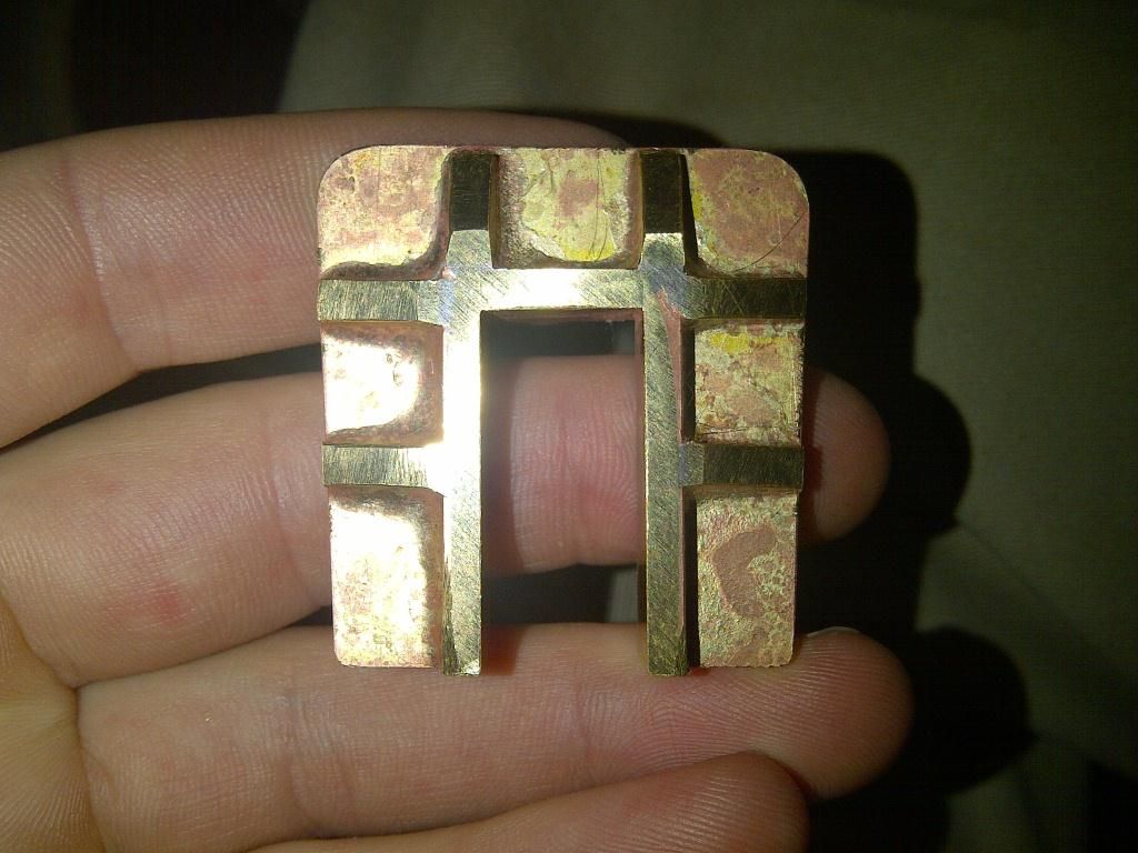
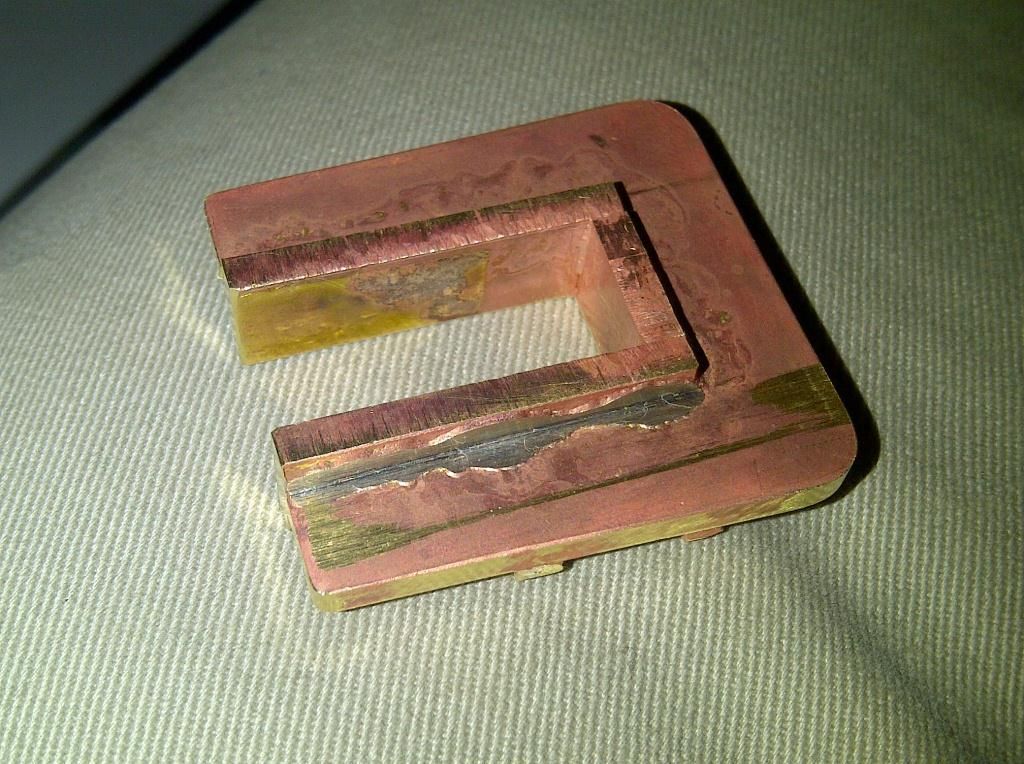
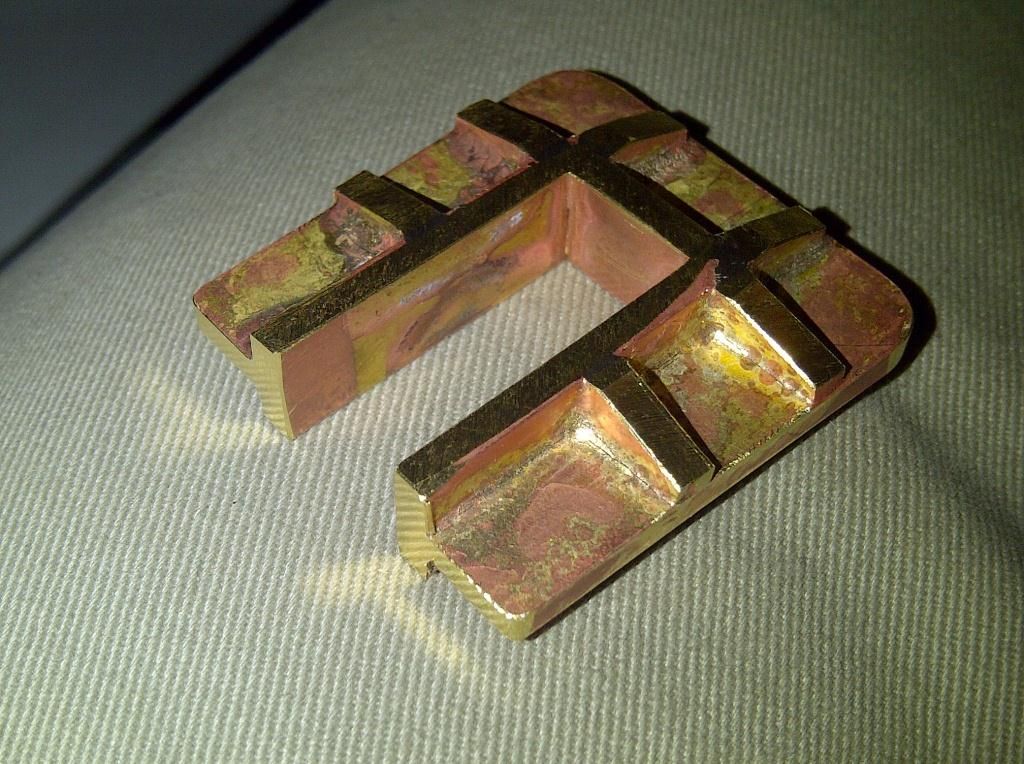
          Here is a picture of my first test fabrication of a hornblock. I needed to include for machining as well, hence it it quite bulky. Also you will see I did not include for the bolting faces required at the bottom.1 test hornblock.jpg

          Below is the back side of the block.

          2 test hornblock 2.jpg

          Another view

          3 test hornblock 3.jpg

          Edited By Ryan Norton on 17/12/2013 09:34:13

          Edited By Ryan Norton on 17/12/2013 09:36:40

          #138107
          Ryan Norton
          Participant
            @ryannorton40317

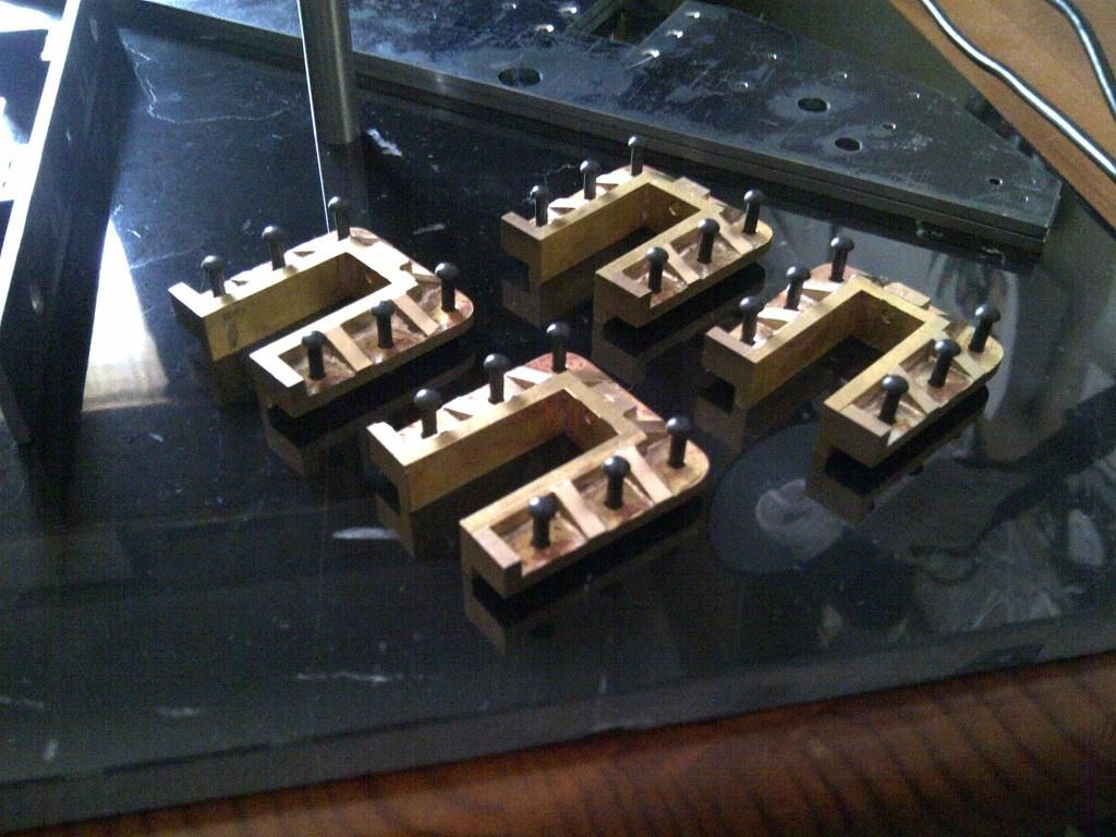
            Here are the four final hornblocks after drilling for rivets. Machining of the inside is still required.

            7 hornblocks after fabrication and final machining.jpg

            #138109
            Ryan Norton
            Participant
              @ryannorton40317

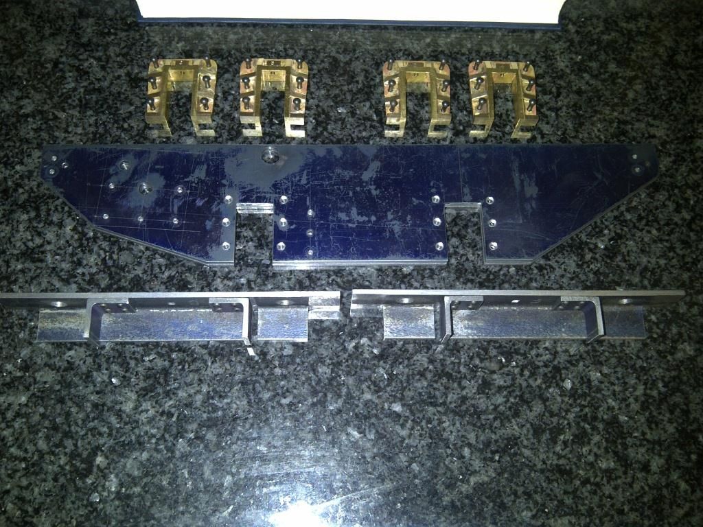
              Here is a photo of the frame plates finished to size and drilled accordingly. Also you can see the buffer beams and hornblocks.

              5 hornblocks, frame plates and buffer beams.jpg

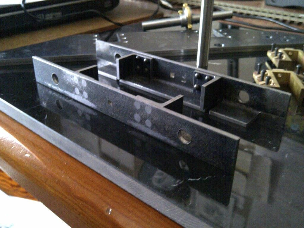
              Below is a view of the buffer beams with angles rivetted on.

              8 buffer beams after rivetting the angles.jpg

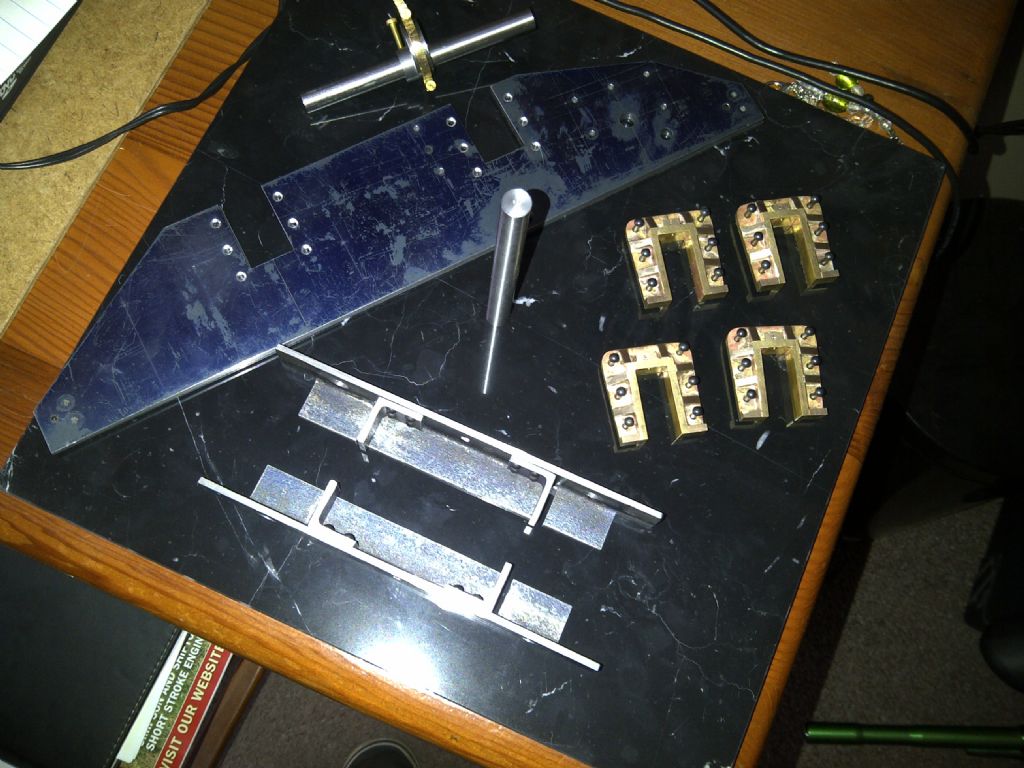
              All together.

              6 bits and pieces.jpg


              Edited By Ryan Norton on 17/12/2013 09:53:12

              #138129
              OldMetaller
              Participant
                @oldmetaller

                Hi Ryan, I'm really pleased to see this thread as I have just started a small-boilered Tich and intend to fabricate most of the parts! This will be my first 'big' locomotive, I've only worked in 16mm before. It looks like you've got off to a flying start and I shall be following your build closely! I'm at about the same stage as you, except that instead of making the hornblocks, I'm part way through making the wheels from round mild steel bar. Good luck with the build!

                Regards,

                John.

                #138147
                David Haynes
                Participant
                  @davidhaynes53962

                  Tich, small as it is, has been a battlefield for many, and l sadly there are many partial builds for sale left as casualties. There are various obvious pinch points which scare off folk. Well done for having a go and I hope you are able to complete it in a good time.

                  #138173
                  Ryan Norton
                  Participant
                    @ryannorton40317

                    Hi guys!

                    Thanks for the words of wisdom and encouragement!

                    I have seen far too many pictures of part-built TICH's and I think they are what have spurred me on and made me more determined than ever to finish this.

                    Just as a matter of interest, what is the correct phonetic pronounciation of TICH? I have heard many variations and would like to know the intended option!

                    #138174
                    Ryan Norton
                    Participant
                      @ryannorton40317

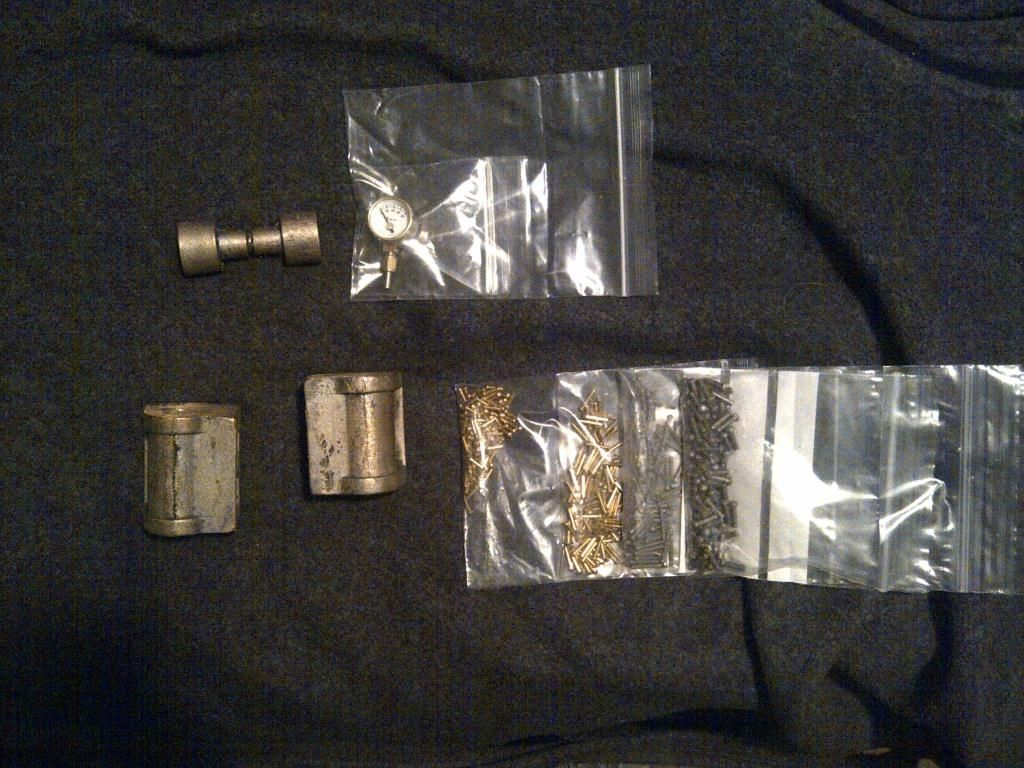
                      I was a little bit aprehensive about fabricating my own cylinders and therefore decided to buy the cylinders and the piston castings as well as other items not readily available in our country from REEVES.

                      With hind site and what I have learned during this build so far, I would definately have tried to fabricate the cylinders myself.

                      Below are the items procured from REEVES

                      9 the only commercially bought items.jpg

                      #138175
                      Ryan Norton
                      Participant
                        @ryannorton40317

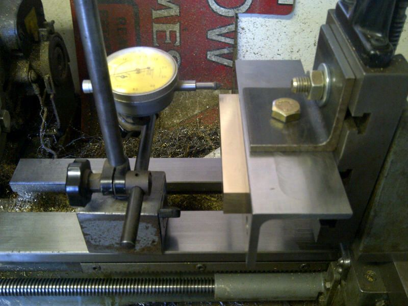
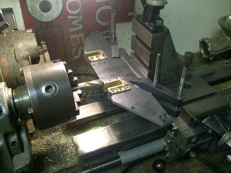
                        Below is the setup I used to machine the axleboxes and hornblocks. The procedure was carried out exactly the way it is described in Curly's book.
                        9.2 machining the axleboxes.jpg

                        9.3 machining the hornblocks.jpg

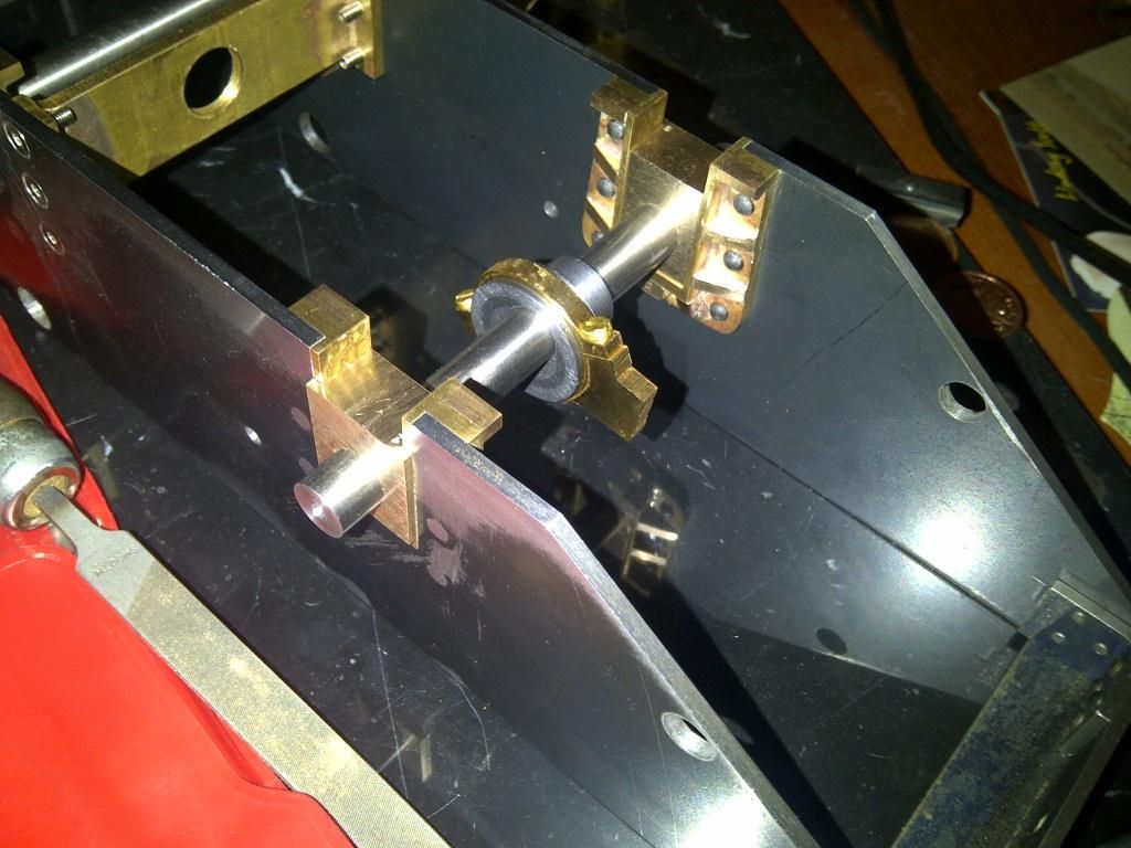
                        Here you can see the final fitting of the axleboxes in the hornblocks which have been machined. You can also see the pump eccentric and collar on the rear axle.

                        10 final fitting of the axle boxes and axles.jpg

                        12 final fitting of the axle boxes and axles 2.jpg

                        #138176
                        Ryan Norton
                        Participant
                          @ryannorton40317

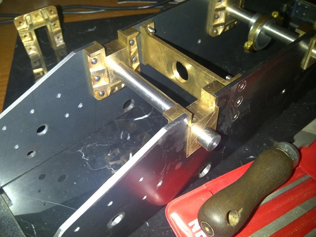
                          In the book, LBSC describes a fabricated pump stay which is made from brass and bent to form the two 90 degree bends. These are further machined to the correct size.

                          After trying once and failing, I decided to fabricate the stay from three pieces of brass and then machine it.
                          This worked and you can see the result below. (The allen screws still need to be cut to length)

                          Also, while I am talking "screws", I have tried where possible to use the suggested screws of imperial nature, however in SA we mostly have metric stuff available and therefore my fastener usage in the build will be a closely fitting mish mash of imperial and metric. Just in case you were wondering.

                          11 fabricated pump stay.jpg

                          #138177
                          Ryan Norton
                          Participant
                            @ryannorton40317

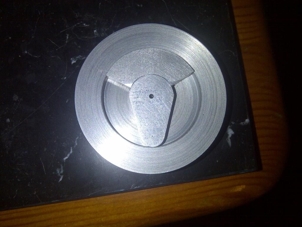
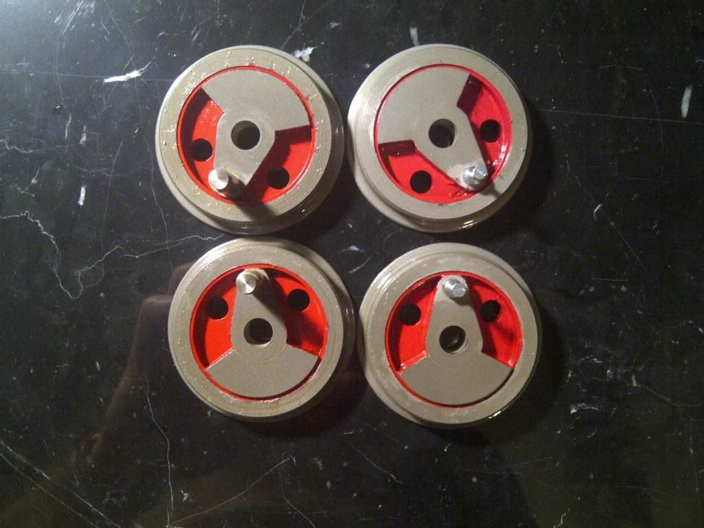
                            The wheels for my TICH have been fabricated from scratch as well using slices of EN8.

                            The slices were faced and a 1.6mm centre hole was drilled all the way through. This was used to locate the boss and was opened out after soldering, for the axle hole.

                            Below is a picture of one wheel with all parts in place.

                            13 wheel fabrication.jpg

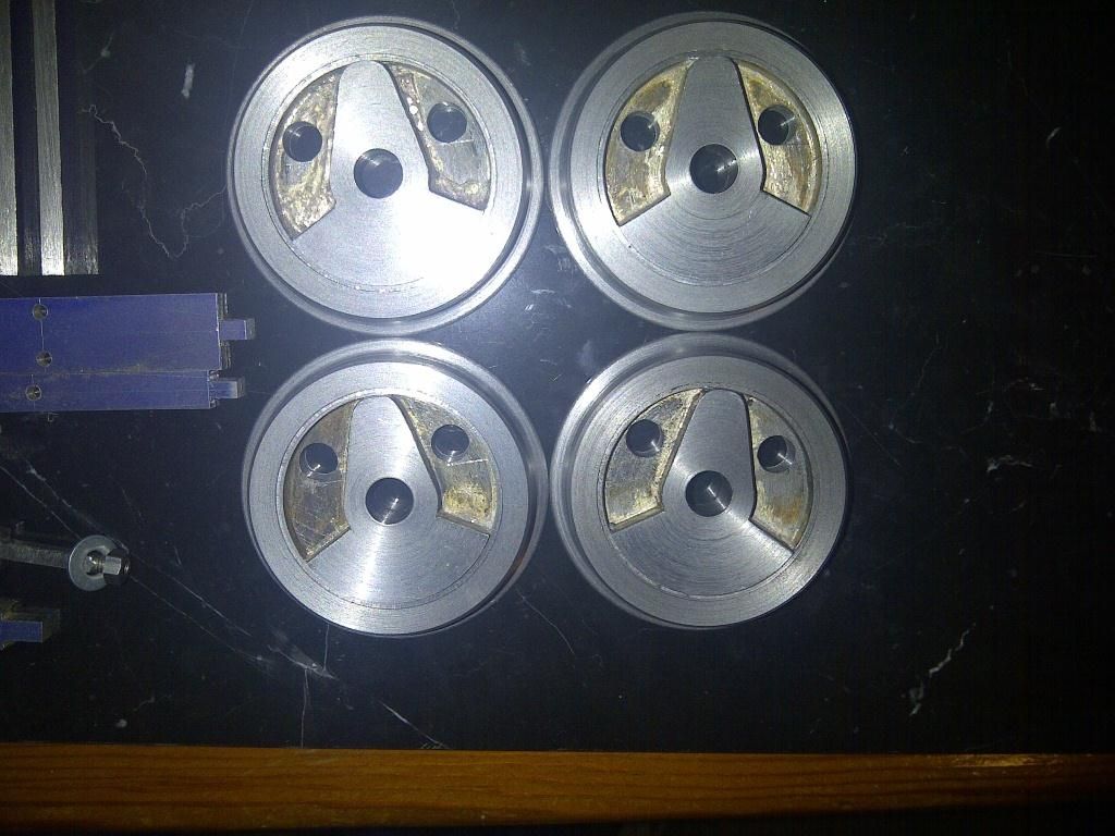
                            The bosses and counterweights were made seperately and fitted within the inner diameter of the wheel.

                            Below is the result post soldering. I could not pickle the wheels immediately as the material used was EN8 and if subjected to quenching would have resulted in a hard brittle wheel that would prove difficult to machine.

                            I therefore waited 24 hours before scrubbing the excess flux off and cleaned the wheels up.

                            14 wheels after soldering and final machining.jpg

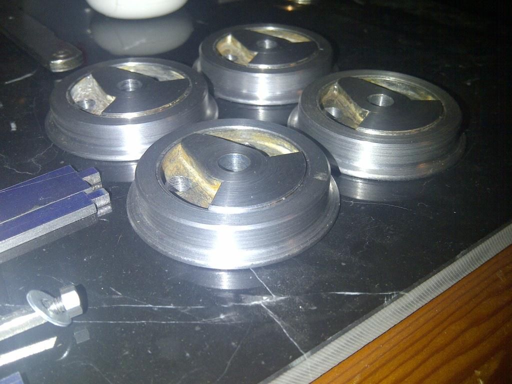
                            After silver soldering, the wheels were machined as per the words and music, using the fabricated backplate described.

                            14.2 wheels.jpg

                            Finally the wheels were sandblasted, degreased and masked up for painting. The first coat was an etch primer and then an aerosol to follow, using signal red.

                            15 wheels after sandblasting and painting.jpg

                            There are still some sticky bits on the wheels from the masking tape used. In this picture the crank pins have been pressed into the wheels already.

                            #138178
                            Ryan Norton
                            Participant
                              @ryannorton40317

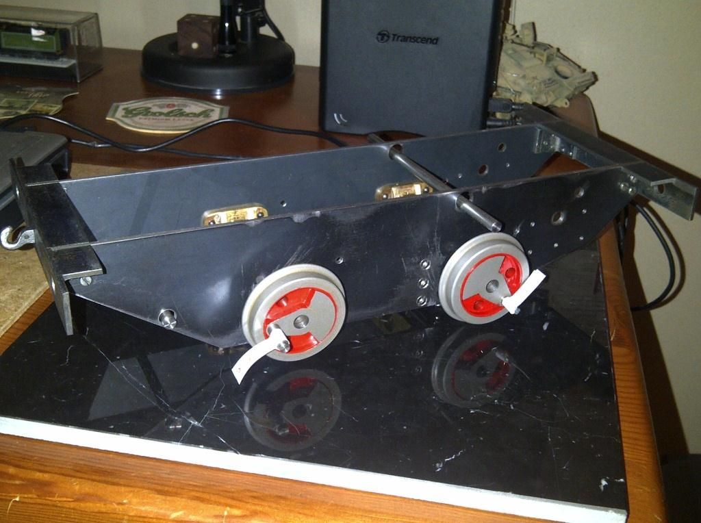
                              The next step in the build was to quarter the wheels. This had been frightening me ever since I had read about it as once the wheels are pressed onto the axles there is no going back. I have read many different ways of quartering wheels but settled on the method described by LBSC in keeping with his theme.

                              The axles were turned down to the appropriate press fit tolerance and the first wheel pressed all the way onto the axle using the bench vice as a press as described. Success, however, now came the difficult part, quartering the wheels.

                              It is important to remember at this point that if you are using slip eccentrics, now is the time to put them on the front axle. The pump eccentric also needs to be fitted to the rear axle before the other wheel is pressed on.

                              After much procrastination and messing around I took the plunge. Using LBSC's method for quartering I pressed on both wheels. This method is not the best and can be highly affected by the error of paralax, however if both sets of wheels are finished using the same procedure, in theory there should be no issue, provided the error was the same for both sets.

                              This was very stressful but worked out in the end.

                              16 frames together and test fitting wheels for quartering and pressing.jpg

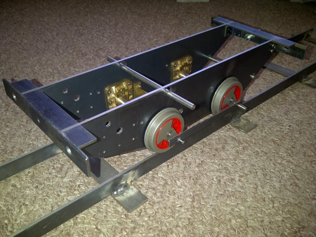
                              17 rolling chassis.jpg

                              The coupling rod template can be seen in this picture.

                              #138179
                              Ryan Norton
                              Participant
                                @ryannorton40317

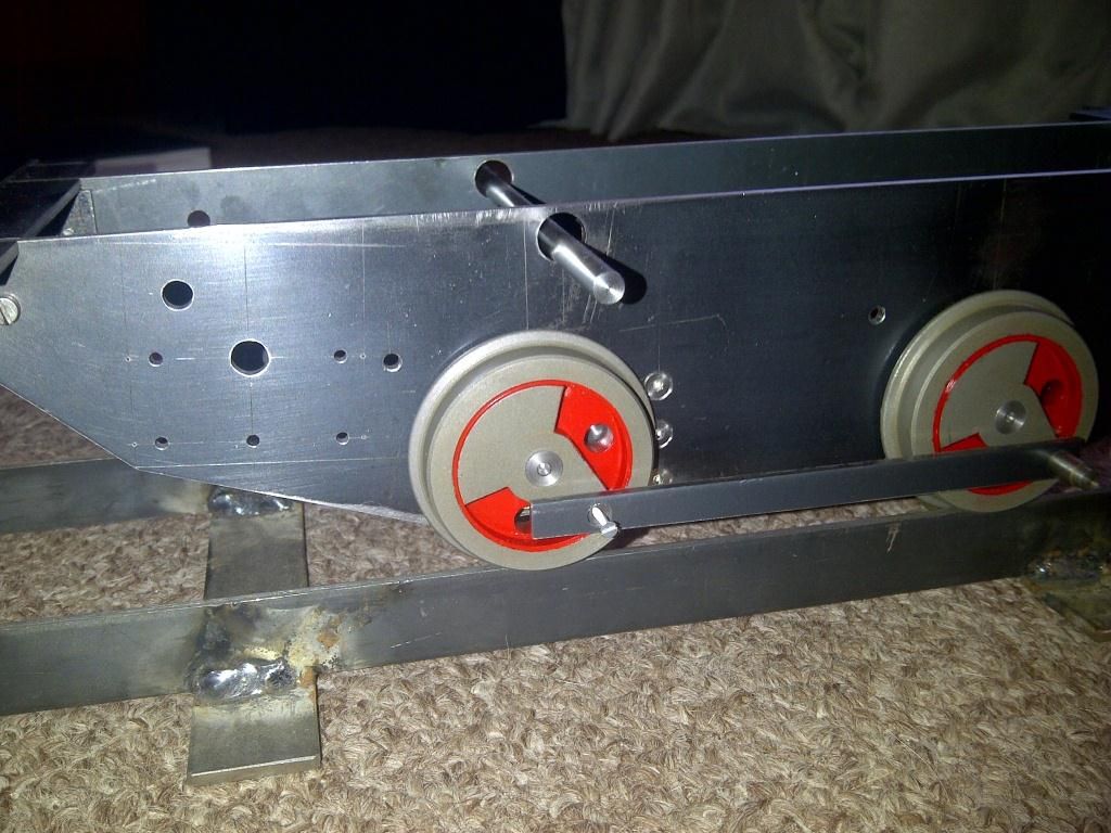
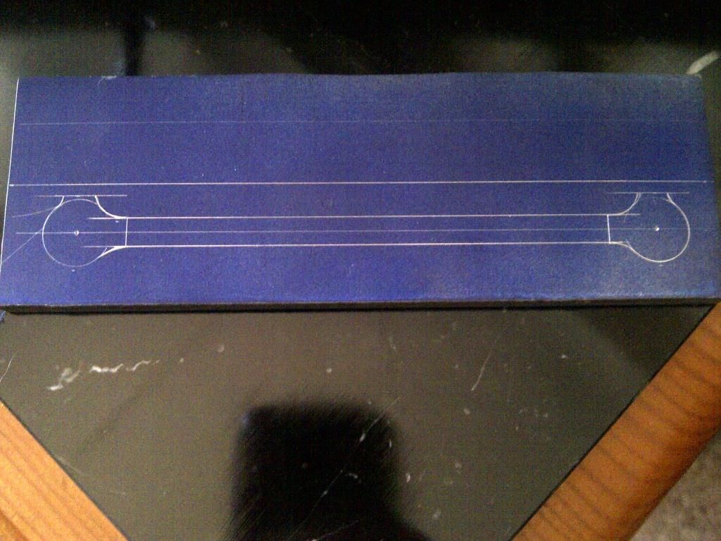
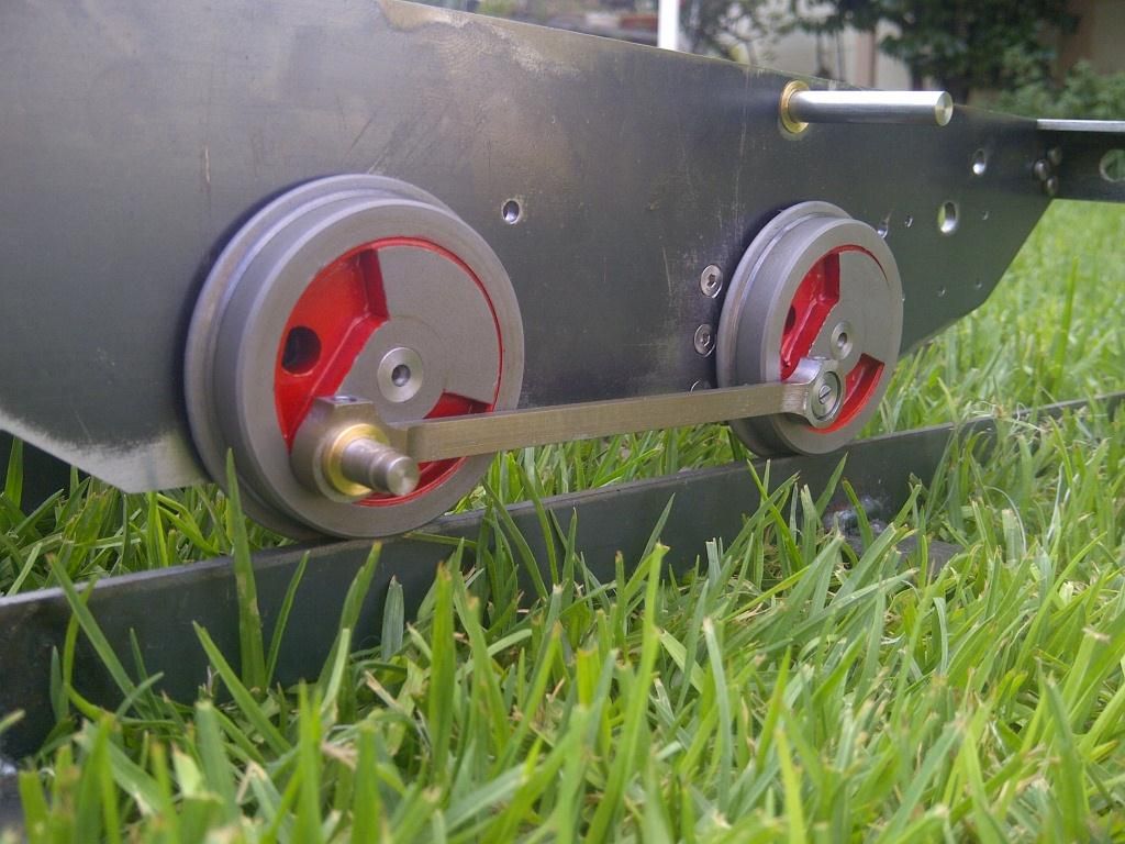
                                The coupling rods were the next stage. The centres of the crank pins should, in theory, be the same as the axle centres, however with human error in the mix, it is always better to check your as built dimension before following the words and music directly. I found that my dimension was almost exactly what is described but not quite and therefore made the appropriate adjustment to size.

                                A test piece was quickly cut out and drilled to the corresponding measurement and it worked! I did make two and there was some slight binding at a certain point. This was rectified and a design was drawn up and marked out.

                                18 test piece for final as built length required for coupling rods.jpg

                                18.1 coupling rod marked out.jpg

                                Below are the coupling rods on the wheels

                                21.1 rhs coupling rod.jpg

                                #138180
                                Ryan Norton
                                Participant
                                  @ryannorton40317

                                  When I have time, I will take some photographs of all of the tools described in the words and music that I have made, which are required for certain machining procedures etc.

                                  I find it fascinating and very satisfying to make things required to make things. It sometimes feels like you are being side tracked but in the end it is all worth while. You just cannot rush…..!!!

                                  Edited By Ryan Norton on 18/12/2013 07:41:12

                                  #138181
                                  Steamer1915
                                  Participant
                                    @steamer1915

                                    This is excellent work Ryan. Please keep the pictures coming.

                                    Steve.

                                    #138184
                                    Ryan Norton
                                    Participant
                                      @ryannorton40317

                                      Thanks Steve! Much appreciated.

                                      I will do!

                                      #138186
                                      Ryan Norton
                                      Participant
                                        @ryannorton40317

                                        Here is a picture of all of the blobs

                                        19 bits and bobs.jpg

                                        You will notice on the right side of the picture, the pump eccentric has been painted red in the same fashion as the wheels were. Also, here yoiu can see the suspension springs and the corresponding holes in the axle boxes.

                                        The springs were made on the lathe using piano wire and the screw cutting train on the lathe. The TPI was guessed really, but it seems to work…

                                        The axle driven pump body can also be seen in this picture, however this was a failure and was remade later.

                                        #138187
                                        Ryan Norton
                                        Participant
                                          @ryannorton40317

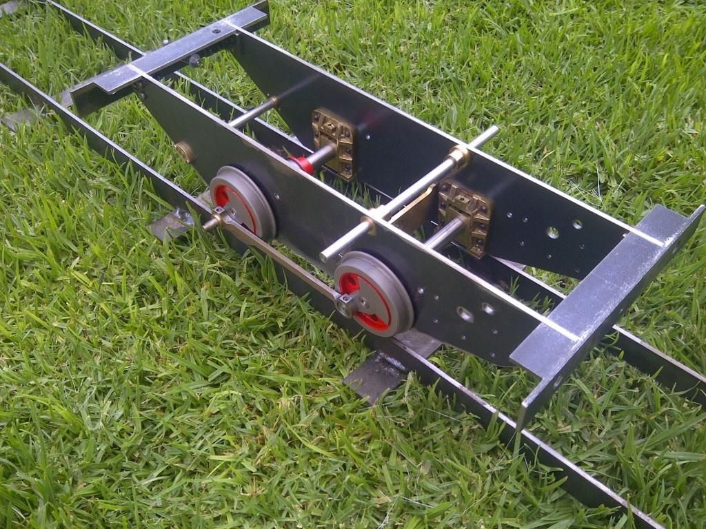
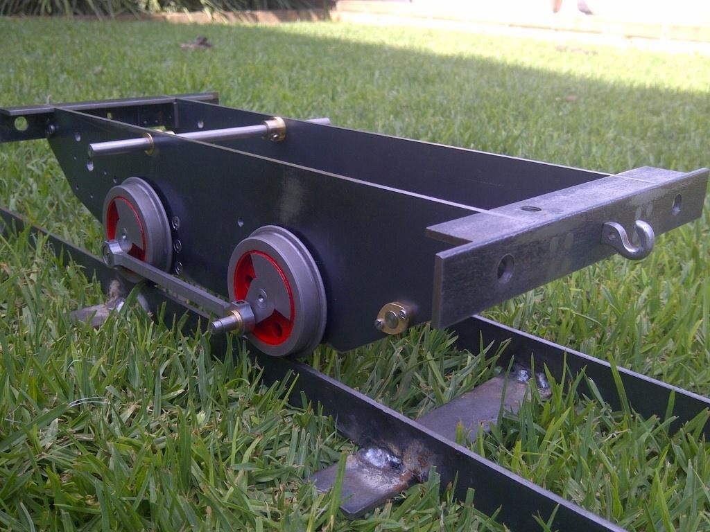
                                          Some other pictures

                                          20 tich on the rails.jpg

                                          22 brake shaft and bush, coupling hook.jpg

                                          #138188
                                          Ryan Norton
                                          Participant
                                            @ryannorton40317

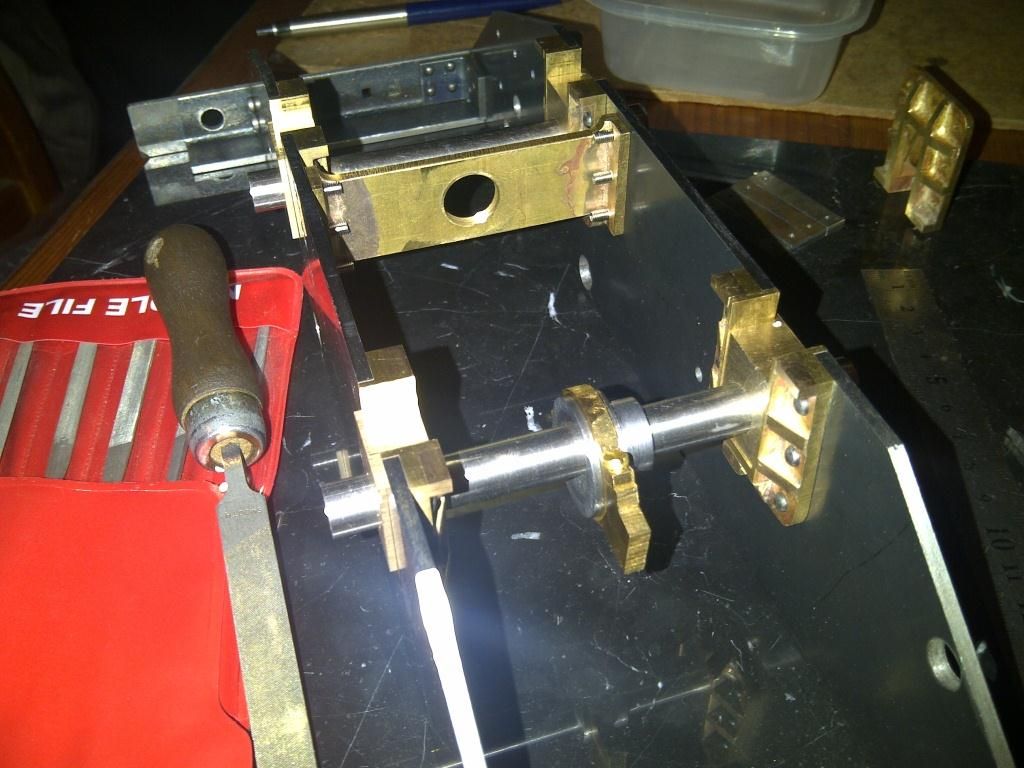
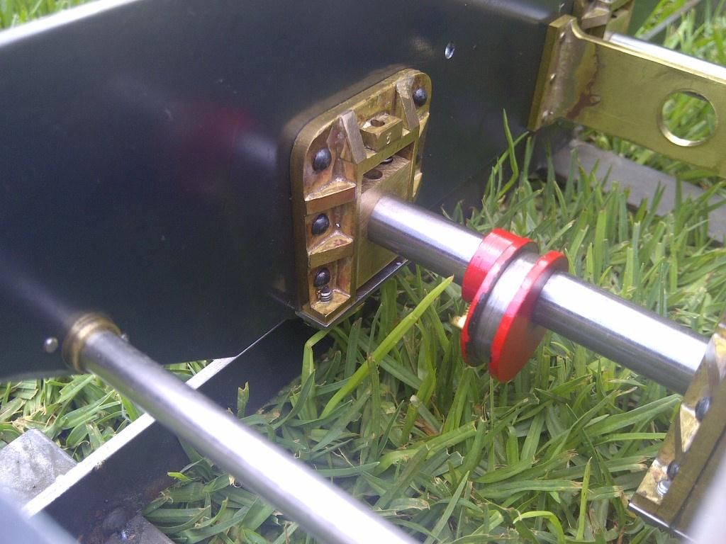
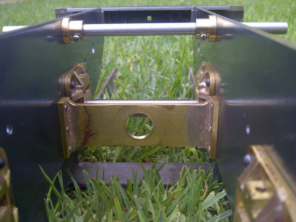
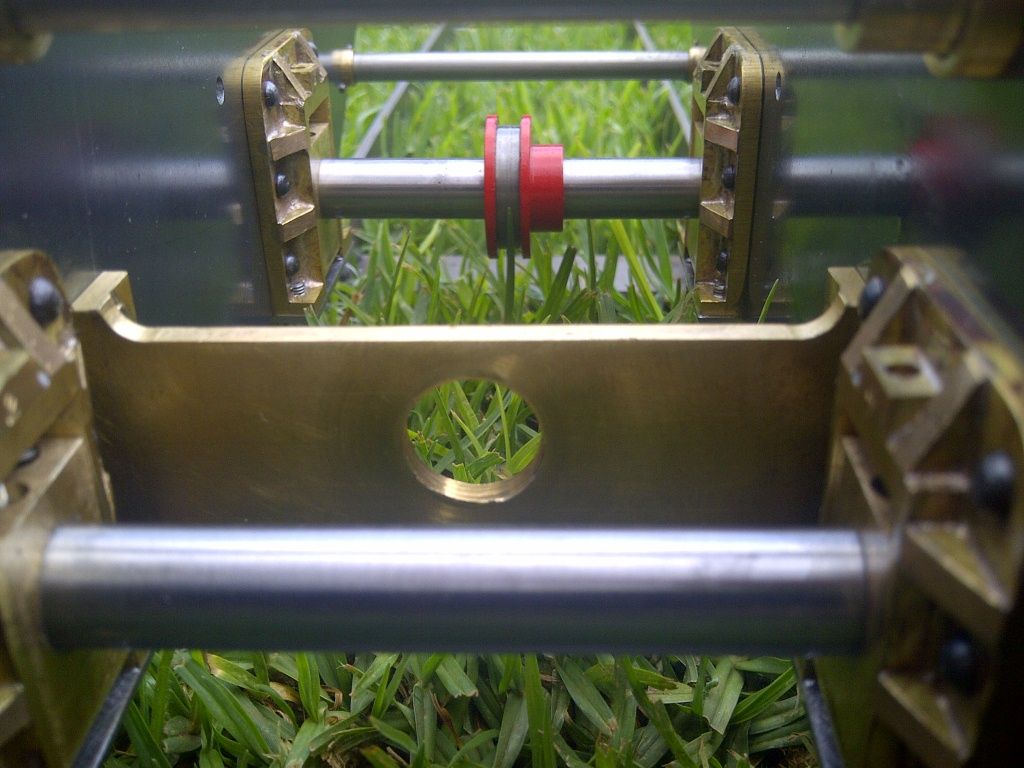
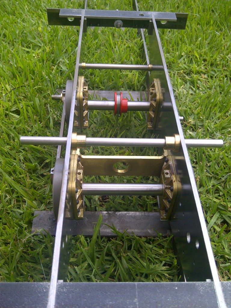
                                            Here are some close ups of inside. One thing I did include for which is not mentioned in the words and music is additional lubrication for the axles. On the top of each hornblock you will see a small brass block with a hole in it, this is for a lubrication pipe which will be connected up to a manually refillable reservoir.

                                            1 close up rear axle.jpg

                                            2 close up pump stay and reversing shaft.jpg

                                            Above is a better view of the fabricated pump stay.

                                            3 close up axles, pump stay and brake shaft.jpg

                                            4 ga.jpg

                                            #138214
                                            Another JohnS
                                            Participant
                                              @anotherjohns
                                              Posted by Ryan Norton on 18/12/2013 07:27:30:

                                              The next step in the build was to quarter the wheels. This had been frightening me ever since I had read about it as once the wheels are pressed onto the axles there is no going back. I have read many different ways of quartering wheels but settled on the method described by LBSC in keeping with his theme.

                                              The axles were turned down to the appropriate press fit tolerance and the first wheel pressed all the way onto the axle using the bench vice as a press as described. Success, however, now came the difficult part, quartering the wheels.

                                              It is important to remember at this point that if you are using slip eccentrics, now is the time to put them on the front axle. The pump eccentric also needs to be fitted to the rear axle before the other wheel is pressed on.

                                              HI Ryan;

                                              My Tich is my favourite locomotive for taking out to the track. Not an all day steamer (unless you convert it to oil, as per directions in Model Engineer a decade or two ago) but more fun than the larger locomotives.

                                              Slip eccentrics on the front axle – I put mine on the rear, and the ash pan is a bit of a bother!
                                              Are you going to update the boiler to modern construction methods (rivets for side stays, silver soldered, nothing threaded into the boiler shell directly, i.e., not into a bushing) or use the "words and music"?

                                              Keep up the great work –

                                              Another JohnS.

                                              #138217
                                              IanT
                                              Participant
                                                @iant

                                                Hi Ryan,

                                                A very nice job you are doing there – congratulations.

                                                Not sure how to phonetically spell Tich but the best I can offer is that "Tich" is like 'ITCH' with a 'T 'in front !!

                                                Keep up the running commentary, I'm sure everyone will enjoy watching your progress.

                                                Regards,


                                                Ian T

                                                Edited By IanT on 18/12/2013 15:59:41

                                                #138218
                                                OldMetaller
                                                Participant
                                                  @oldmetaller

                                                  Hi Ryan, I love the way you've done the wheels, I'm still at the stage of having four slices of mild steel, waiting for me to make the drawbar for the 2MT mandrel I intend to use for turning the wheels to profile. I think I may fabricate the boss and balance weight like you have done. The red looks great too!

                                                  I too have used some metric threading…my fabricated pump stay is tapped 12mm for the pump body.

                                                  'Tich' is said as though it is spelled with an extra 't'- 'Titch', the 'ch' being like the beginning of 'church'. You sometimes see it spelled with the extra 't' on ebay or even in Model Engineer!

                                                  Good luck, and keep up the good work!

                                                  Regards,

                                                  John G.

                                                  #138246
                                                  Ryan Norton
                                                  Participant
                                                    @ryannorton40317

                                                    "Slip eccentrics on the front axle – I put mine on the rear, and the ash pan is a bit of a bother!

                                                    Hi John, my mistake the slip eccentrics are supposed to be on the rear axle. embarrassed

                                                    As for the boiler, I had planned on following the words and music as I know that is should work. I will however try and make the boiler to the best possible standard and if this means I need to alter the construction method slightly, then so be it.

                                                    #138247
                                                    Ryan Norton
                                                    Participant
                                                      @ryannorton40317

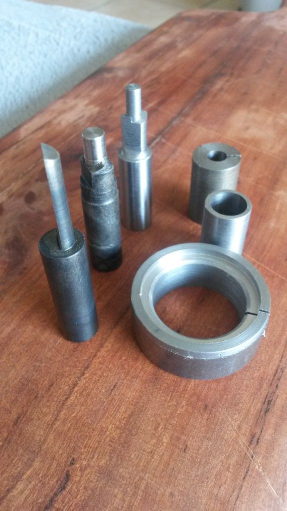
                                                      As I said yesterday, I would post some pics of the tools described in LBSC's book.

                                                      Below are a few that I have had to make thus far (see the captions below the pictures):

                                                      1 tools.jpg

                                                      From the left, a D-bit, two different size counter-bores, two different size split bushes and the step chuck/bush required for turning the cylinder covers.

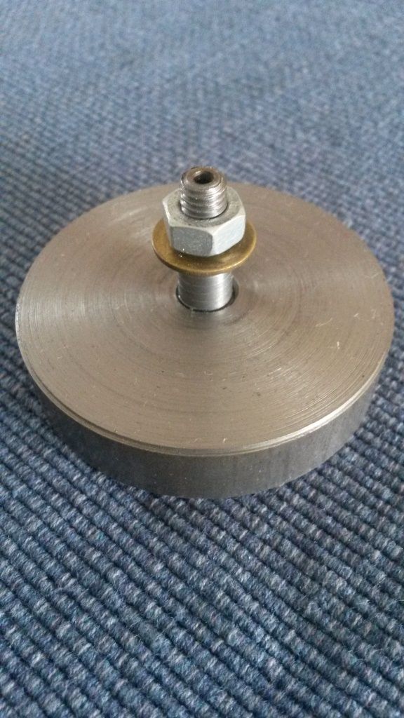
                                                      2 wheel turning jig.jpg

                                                      Above is the jig described for turning the wheels.

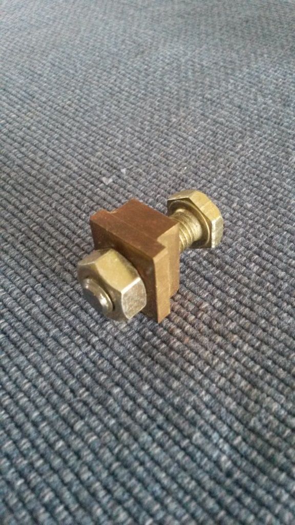
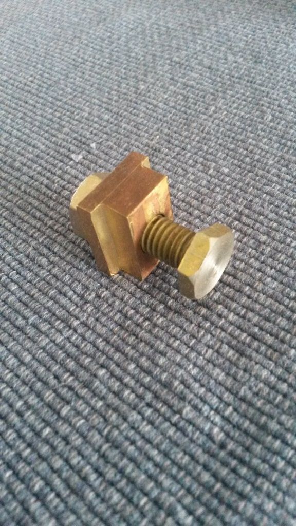
                                                      3 hornblock machining clamp.jpg

                                                      3.1 hornblock machining clamp.jpg

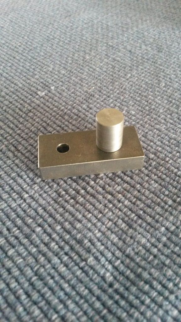
                                                      Above is the clamp for machining the hornblocks. The part that looks like an axle box fits into the hornblock, whilst the tee bolt slides into the vertical slide of the lathe. The nut is used to tighten/clamp the horn block to the slide ready for machining.

                                                      4 crank pin hole drilling jig.jpg

                                                      Here is the crank hole drilling jig. The boss fits snugly into the wheel axle hole and the whole lot is clamped up tightly. The hole is then used as a guide to drill the crank pin holes. This setup allows for very accurate drilling of the pin holes at a specific distance from the axle hole.

                                                    Viewing 25 posts - 1 through 25 (of 303 total)
                                                    • Please log in to reply to this topic. Registering is free and easy using the links on the menu at the top of this page.

                                                    Advert

                                                    Latest Replies

                                                    Viewing 25 topics - 1 through 25 (of 25 total)
                                                    Viewing 25 topics - 1 through 25 (of 25 total)

                                                    View full reply list.

                                                    Advert

                                                    Newsletter Sign-up