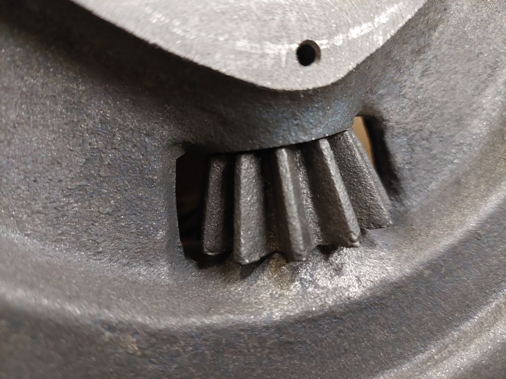
20 degrees vs 14.5 degrees pressure angle for gears
20 degrees vs 14.5 degrees pressure angle for gears
- This topic has 41 replies, 14 voices, and was last updated 19 December 2022 at 14:48 by
Anonymous.
- Please log in to reply to this topic. Registering is free and easy using the links on the menu at the top of this page.
Latest Replies
Viewing 25 topics - 1 through 25 (of 25 total)
-
- Topic
- Voices
- Last Post
Viewing 25 topics - 1 through 25 (of 25 total)
Latest Issue
Newsletter Sign-up
Latest Replies
- Square end on round stock – Milling?
- I’m Under Pressure
- File backup to external hard drive, incremental etc?
- Boiler Design – issue 4765
- Transwave converter – plugged in motor, tripped RCD
- Sat nag
- motor and switch wiring Myford ML7
- Taylor Hobson cutter grinder modificaton
- Easiest/cheapest source of R8 socket
- Twin Engineering’s heavy mill/drill quill removal


 Initially had trouble with the photo, finally found a way to post it the dimension I'm struggling with is the one marked in red, is this meant to be 1 – 7/8" not just 7/8" I know the drawing is to scale and it certainly bigger than 7/8" .
