Mine stops more quickly using the normal stop as that brakes the motor electrically. Using the Estop to cut all power means that it will stop no matter what the fault.
Thanks Duncan – by normal stop, do you mean the Estop on the VFD controller/ inputting to the VFD, or do you mean fitting the Estop to the power cable? I think Robert said above cutting power in the cable takes longer, as the VFD Estop operates with a brake? Sorry if I'm confused.
In a properly set-up VFD system using the E-Stop input will stop the machine faster than the normal stop button.
Cutting the power to a VFD with the E-Stop is not recommended as the VFD stores significant energy in the "bridge" capacitor(s). The electronics won't even recognise that power is cut until the voltage on this drops. Thus the stopping time is much longer than even a non-VFD motor with a power cut E-Stop. This is made worse by using an oversized VFD or when the load is light.
So a dedicated E-stop input is the best solution.
Chris,
As they say it has a filter built in you probably don't need an external one.
In theory a full set of electromagnetic emissions measurements should be carried out to ensure compliance with regulations. In practice this is seldom done for one-off designs even by professionals. The cost, typically a few thousand pounds, has a lot to do with it.
Sorry to be slow Robert, I had an eight-hour round trip to Stansted to pick up my lad from the airport yesterday, after his flight back to Bristol on Monday was cancelled. How do people cope with travelling regularly on the M25?! Horrible.
Anyway, thanks for that, we'll skimp on the emissions measurements. Our steel wall box is ordered from RS Components and arriving tomorrow, I think I know what we're doing now!
If I use a steel gland connected directly to the screen mesh (clear cover removed from just that part of the cable) and earth the gland, do I no longer need to earth the screen?
On the other hand, if I earth the screen and use a plastic gland, I only need to earth the screen, not the gland?
A steel gland that directy contacts the mesh (screen or armour) on the cable and is fastened through the metal box is the ideal solution. No other connection to the mesh / screen is required in this case. The matal case must of course be connected to mains earth. The inside of the box under the gland nutsmust be free of paint or similar finishes.
If you use a plastic gland on the box then leave the mesh and outer insulation intact up to within a few inches of the VFD. One good way to earth the screen in this case is to use a 15mm compression fitting for water pipe. Fold the mesh over the olive and clamp it with the nut. Iflike most, the olive has a sharp edge break it with a file so it doesn't cut the mesh. Mount the fitting on a angle bracket fastened ot the same metal plate / box wall as the VFD.
The plumbing fitting trick is not good for the outside of the box because it does not provide mechanical support for the cable.
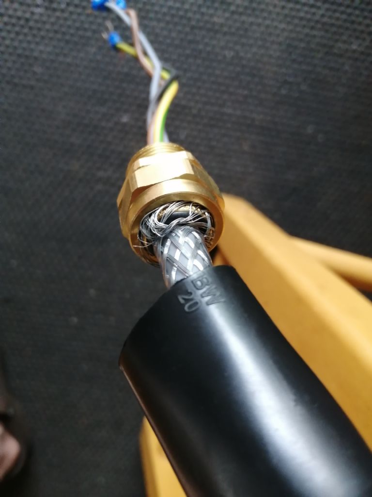
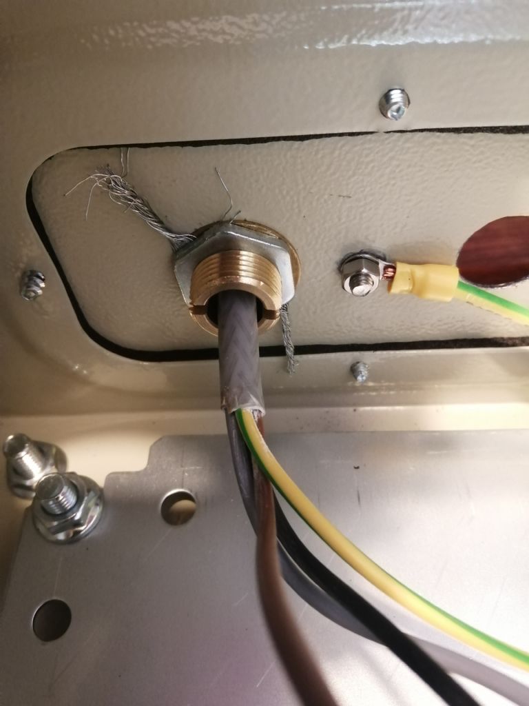
Is this how you'd expect the screen to be connected to the earthing gland? It looks a bit scrappy to me, but the wires are held firmly to the gland. The gland was described as suiting the size of cable but was in fact larger, so I put an O-ring between the inner insulation and the screen wires to take up the slack.
Yes, it's not as secure as the other end, which has a plastic/ nylon gland that squeezes down onto the cable. It is fairly secure though, and we'll connect the cable to the wall so there's no chance of it getting tugged.
Is there any reason not to use regular, unscreened cable for the single phase power input, together with a plastic gland? It'd be easier, if there's no need for the screen and earth to the gland.
Chris, whilst the brass gland will provide screening it may not give good mechanical support. If the cables are otherwise fixed this may not matter. The type of gland used appears to be made for SWA (steel wire armoured) cable where the armouring is of much heavier steel wire galvanised, this may account for the loose fit. Noel
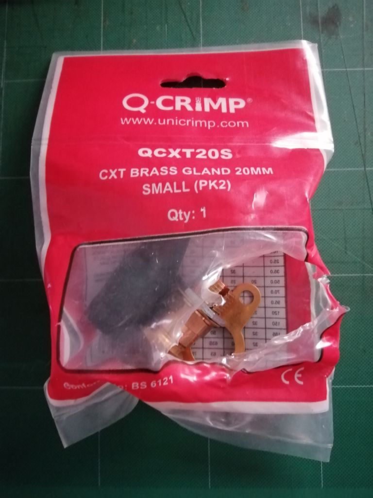
ETA – Noel – is there a type of gland dedicated to screen rather than armour? I can see what you say is correct, the videos I've watched all use armour cables which are much more substantial. I'm happy to swap the gland for the correct type if I can find it.
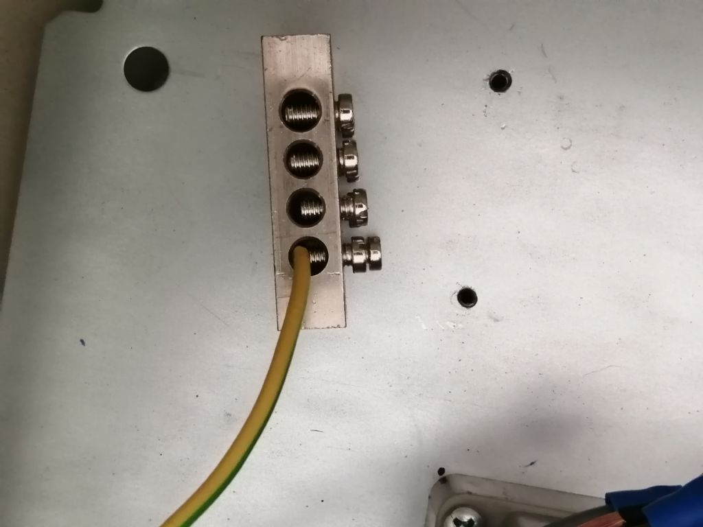
Also – I'm using an earthing block, but the connection doesn't look terribly good compared to a round crimp connector attached to the back plate by a bolt. Two earth cables will go in (from the in and out power cables), one out to the vfd. Does the earth block look ok, or should I fit a bolt and have three crimp connectors onto it?
Is there any reason not to use regular, unscreened cable for the single phase power input, together with a plastic gland? It'd be easier, if there's no need for the screen and earth to the gland.
Ordinary cable for the input unless there's a specific reason for screening it, which is unlikely in an ordinary workshop.
If an EMC problem is bad enough to suggest the input cable needs screening, then a proper analysis of the problem is needed. Fitting a screened input cable out of context costs time and money and could easily make the problem worse.
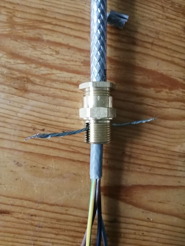
Thanks all. We went back to the shop and bought a different type of earthing gland, the screen passes through the gland, is formed into a couple of pigtails and those are held in the two slots in the thread by a copper washer and a nut. It's now mechanically secure. The 240v input is now a rubber-coated cable, 1.5mm2, connected to the enclosure with a plastic gland.
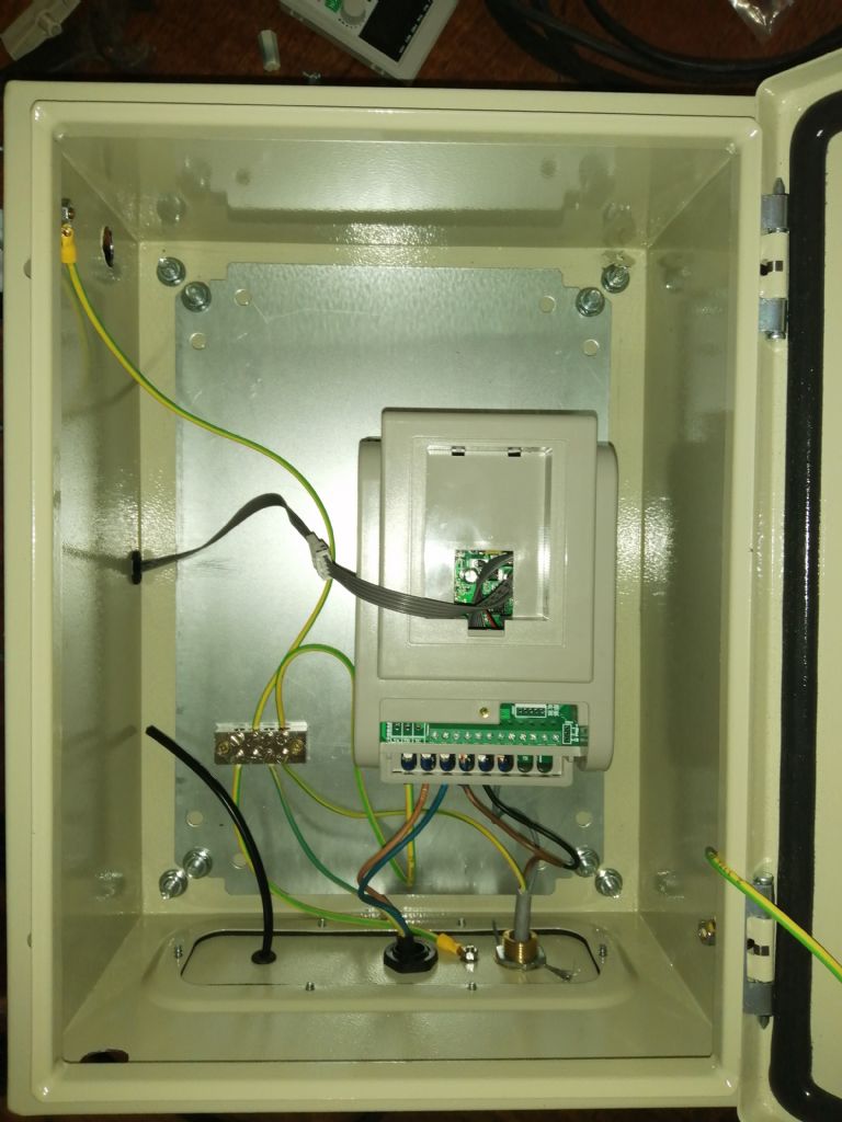
Can you take a look at the setup within the enclosure and let me know if you can see anything obviously wrong? We still need to snip off the screen pigtails and the black cable yet to be connected is for the Estop.
Thanks all. We went back to the shop and bought a different type of earthing gland, the screen passes through the gland, is formed into a couple of pigtails and those are held in the two slots in the thread by a copper washer and a nut. It's now mechanically secure. […]
I'm thinking to convert our lathe from single phase to 3 phase with an inverter. Top speed on our lathe is 2105; speed on the 4 pole we're looking at is 1400, and the 2 pole is 2800. So far we've not gone beyond the 600 that the slow pulley gives and that seems fine for now, but that may change.
From what I've read, it's ok to run the motor at 60 Hz and increase the 4 pole speed to about 1700. Is that correct, and if so, given that it doesn't look like we'll be doing much at high speeds/ narrower diameters, would 4 pole be a better bet for us?
I guess my question in short is, is there any disadvantage in using a 2 pole motor compared to a 4?
I bought one of the early Newton Tesla conversion kits for my ML-7 a good few years ago. At the time they routinely set the VFD's frequency range to 0-60 Hz. I was planning to upgrade the headstock bearings/spindle to bronze shells and hardened spindle, so I asked them to programme the VFD for 0-120 Hz, which more than doubled the speed range of the lathe. I have been using that configuration for many years now and it works very well indeed.
A small point , but when fitting wire into a hole rather larger than the wire, bend the wire back over to double it's thickness, this will give the screws more to bite on. The box looks as though it's powder coat , it is vital that ANY coating(or paint ) is remover from under screws, bolts Etc to ensure sound connection. In this case round the earth bolt and copper washer for screen fixing. Noel.
A small point , but when fitting wire into a hole rather larger than the wire, bend the wire back over to double it's thickness, this will give the screws more to bite on. Noel.
OK, thanks Noel.
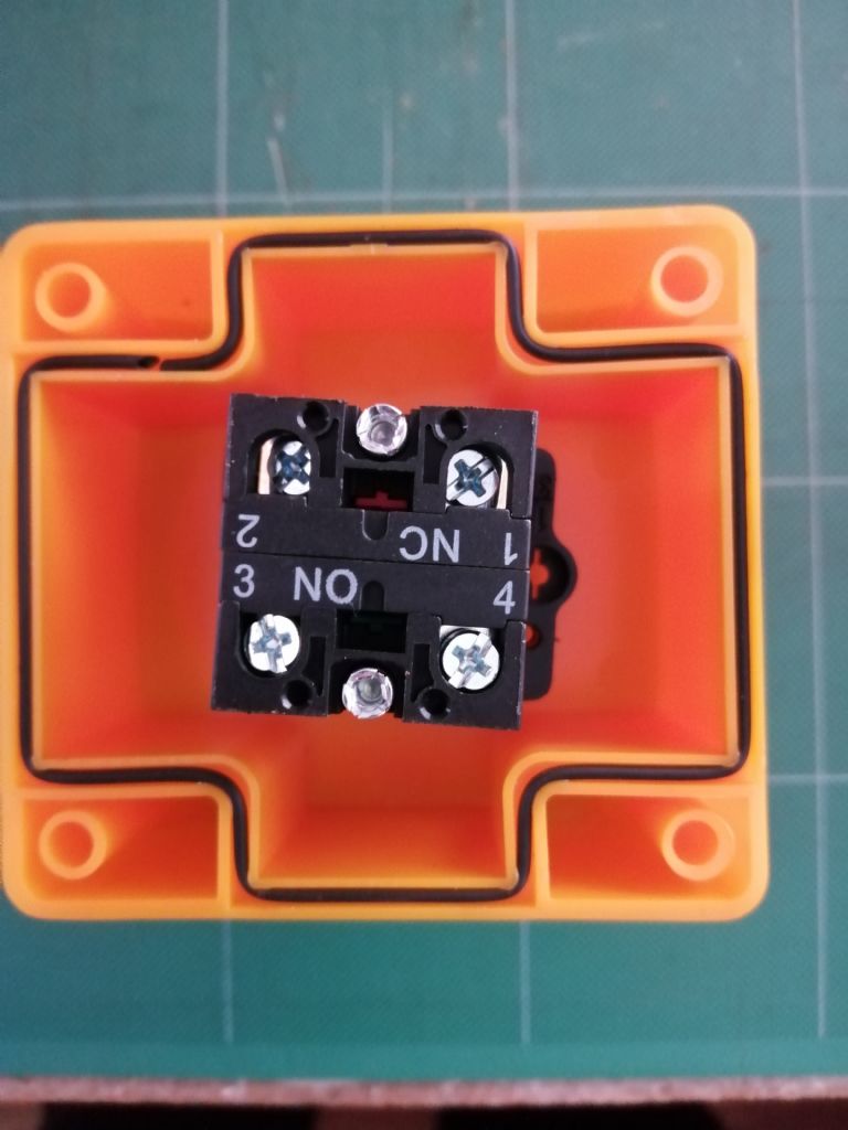
The Estop needs to be Normally Open. I've searched the net but not found an answer – does it matter which wire goes into 3 and which into 4? One will connect to Com on the VFD, the other to port X6.
Small perfectionist point, as Chris is doing a better than average installation, I suggest clipping the screen pig-tails from the gland and carefully removing the remains:
Terminating the screen wires and tightening the gland can cause a few damaged strands to eventually break loose, perhaps much later after the cabinet has been warmed cooled and vibrated by using the lathe. Tidying up the pigtail and carefully removing the remains reduces the risk.
Another booby trap: check that the gland really is earthed to the box. Metal to metal contact is required and a thick coat of paint is a good insulator. You can guess how I know!