2 pole or 4 pole for Myford ML7R

Advert

2 pole or 4 pole for Myford ML7R

Home Forums Electronics in the Workshop 2 pole or 4 pole for Myford ML7R

Viewing 25 posts - 26 through 50 (of 84 total)
  • Author
    Posts
  • #657719
    Chris152
    Participant
      @chris152

      Thanks Robert (I also thanked you in my previous post, I should have thanked Noel in that one – apologies Noel!). That's interesting about 6-pole, I'll remember that for the future. And I guess I'll leave the Revolution setting alone – I thought maybe it was going to try running the motor at 2800.

      One final question, I hope – am I ok to fit a regular NVR switch between the plug that's in the wall socket and the inverter? And if so, am I correct thinking that I can connect the earths within the switch using a simple block connector/ barrier strip?

      Edited By Chris152 on 24/08/2023 08:38:56

      Advert
      #657778
      Chris152
      Participant
        @chris152

        ps – I was thinking of an NVR with emergency stop, which is more important to me than the NVR. Since my last post I've read inverters don't like power supply just switching on/ off, so it'd be an NVR switch with emergency stop, after wall plug and before the inverter. I'll use the control panel for starting/ stopping the inverter.

        Something like this:
        https://www.axminstertools.com/kedu-kjd17b-nvr-switch-230v-1ph-102532?utm_source=tag&utm_medium=affiliates&utm_content=2266&tagrid=58983622&glCountry=GB

        Is that an option?

        Edited By Chris152 on 24/08/2023 17:58:24

        Edited By Chris152 on 24/08/2023 17:59:35

        #657802
        Robert Atkinson 2
        Participant
          @robertatkinson2

          Hi Chris.
          You don't or should not need a NVR with a VFD. The VFD whould have a input for an E-Stop switch and a setting for the amount of active braking applied. This is much faster stopping than just cutting power on a standard motor. Just cutting the input to the VFD means it will take LONGER to stop due to the stored energy in the internal "bridge" capacitor(s).
          There should also be a parameter to select if the VFD restarts on power-on. This should be set to NOT re-start on power on. The start and stop buttons need only be low voltage / current momentary switches.

          You should have an isolator. If the power socket is eassily accesible then pulling the plug covers this. I like to put a IEC 60320 C13/14 "kettle lead" plug and socket on the enclosure so you can instantly see that it is unplugged.

          Robert.

          Edited By Robert Atkinson 2 on 24/08/2023 20:08:16

          #657815
          Chris152
          Participant
            @chris152

            OK, I've spent the evening reading and watching on how to set this up Robert – I've not sorted it yet, but things are slowly starting to fall into place, I think. By that, I mean I'm starting to understand how external controls are attached, tho the parameter specs are pretty confusing to me.

            I've also realised, after reading another thread on here, that I need to create/ buy some kind of metal, ventilated enclosure for the inverter. So external controls become a must, I guess.

            Thankfully I'm in no rush and quite enjoying learning all this, tho it doesn't come naturally to me.

            Thanks again Robert.

            #657819
            duncan webster 1
            Participant
              @duncanwebster1

              I strongly suspect there isn't a lot of difference in the rotor and bearings of a 1500 and 3000 rpm motor, so I have no compunction in running a 1500 rpm motor at 75 hz. It hasn't done mine any harm.

              Mine is set up for braking via the VFD, so it stops more quickly using the normal stop button, but I have a second Estop which cuts the power to everything, VFD, ELS etc. You never know, the VFD might have a fault which keeps it going even if you've hit the stop button. Unlikely I know

              #657872
              Chris152
              Participant
                @chris152

                Where did you place the second Estop, Duncan?

                I think I've figured how to attach and program external on, off and potentiometer, following this link

                **LINK**

                (it covers both wiring and parameter setting clearly, which many don't), but am unclear about an emergency stop – is it any different from the normal stop? I'd really like one we could operate with a hip or whatever's nearest to it, so not a regular size button – I think they're called mushroom buttons?

                #657878
                noel shelley
                Participant
                  @noelshelley55608

                  One point to remember with some emergency stop buttons is they may latch ! This means that to reset the button must be turned to pop out – the circuit is now reset ! Noel.

                  #657915
                  duncan webster 1
                  Participant
                    @duncanwebster1
                    Posted by Chris152 on 25/08/2023 10:23:26:

                    Where did you place the second Estop, Duncan?


                    It's on top of the headstock utilising a hole which I suspect was for a machine light mounting. It cuts off the mains supply to the vfd and to a 4 way adapter into which are plugged the low power things, DRO, ELS etc. I think ideally the Estop would cut supply to the main contactor, but I haven't got one. The Estop is not intended to regularly interrupt the power, it's there so if all else fails and I'm in panic mode I can switch everything off. 

                    I did once spend an unhappy half hour trying to work out why everything was dead, yes I'd leaned on the latching Estop.

                    Edited By duncan webster on 25/08/2023 14:28:55

                    Edited By duncan webster on 25/08/2023 14:31:09

                    #657978
                    old mart
                    Participant
                      @oldmart

                      I chose a 6 pole 1hp motor for the Tom Senior light vertical R8 conversion, it can reach 2000rpm, but has been programmed to no more than 1500rpm, which gives a maximum spindle speed of about 3000rpm, which seems a sensible maximum. The benifit of 6 poles is that it looses less torque at lower rpm which with the pulley combinations gives a really good range. I bought from the inverter supermarket and would do so again.

                      #657979
                      Howard Lewis
                      Participant
                        @howardlewis46836

                        Failing to notice that I had somehow latched my E stop cost me time circuit checking until I msaw my silly mistake of leaning on the button!

                        "Experience lets you recognise the mistake the next time that you make it!"

                        Howard

                        #657986
                        old mart
                        Participant
                          @oldmart

                          I have two e-stops on the Tom Senior, both latching and turn them both off to make it harder for unauthorised people monkeying with it. There is a window in the metal box that the VFD is housed in and NST (no start) shows when the e-stops are active and RDY (ready) when the green button can work.

                          #657990
                          Chris152
                          Participant
                            @chris152

                            OK, progress of some sort, albeit perhaps a bit of a cop out. I discovered by accident, amid the day's searching for VFD connection info, an extension cable and mount for the control panel on the inverter – £12 delivered on ebay. With that mounted on a small tv lever arm which I have, and the inverter further away on the wall in a wall box, that's almost me sorted for the time being.

                            I'm struggling to find the emergency stop parameter, tho P58 ('Multi function input,' SP1), option 5 does say 'Emergency stop'; P12 ('Stopping modes' ) option 3 has 'Emergency brake' (alongside Inertial stop, Deceleration stop and Brake stop options); and finally, p50 (Multi function input 1 X1 binding post' ) seems to have option 19, 'Emergency stop' ('seems', as the layout is confusing and p51-55 appear to occupy the same space as 50).

                            So I'm confused as to which is the parameter I need to set – I'm assuming the Estop button is wired as per any external stop button?

                            Finally, reading around the net on metal enclosures for VFDs I read that the metal enclosure needs to be earthed – any suggestions as to which earth cable from the VFD connects to the box?

                            Apologies for so many very basic questions.


                            Edited By Chris152 on 25/08/2023 22:07:15

                            #658060
                            Chris152
                            Participant
                              @chris152

                              A brief one –

                              Apparently the Estop switch for the VFD needs to be Normally Open. Is that because when activated, it completes the circuit and sends a signal to the VFD to operate the brake?

                              Looking at Eswitches online, some are NO/ NC, and inside have one pair of contacts marked NO, the other marked NC. Will I be wiring to just the NO pair (3 and 4) and leaving the NC pair empty? Here's an example switch:

                              Link

                              I can't find a parameter that indicates that the power won't return to the motor once the Eswitch is released, so assuming the programme requires pressing the start button to get going again. We'll see.

                              #658067
                              Robert Atkinson 2
                              Participant
                                @robertatkinson2

                                I can't comment on the paramrters as I don't have the same model drive.
                                The mains earth coming into the enclosure should go to a earth stud on enclosure and a separate earth lead goes from the same stud to the earth termainal on the VFD.
                                If the enclosure does not have a built in stud. use a 4mm bolt. don't forget to remove any paint under it. Use one nut to secure the bolt through the enclosure wall and a second to secure the earth cables. Ideally use ring tags.

                                For the E-Stop, yes just use the NO contact.

                                Robert.

                                #658070
                                Chris152
                                Participant
                                  @chris152

                                  That's great – thanks Robert.

                                  #658236
                                  old mart
                                  Participant
                                    @oldmart

                                    VFD's can be programmed for switches to work both ways, my two e-stops are in series with the normal stop button. The VFD is set for normally on, and to stop when the circuit is broken so all three switches have to be set at normally on for the motor to work. I have used two e-stop switches as they are much more prominant than the stop switch and also latch off. One is on a mag base and extension cable so it can be set in a position suitable for the particular work setup.

                                    Edited By old mart on 27/08/2023 19:00:13

                                    #658261
                                    Chris152
                                    Participant
                                      @chris152

                                      Thanks old mart, I had a hunt through the parameters but couldn't find anything relating to NO/ NC, so best work with it as is I guess. Magnetic base for the Estop sounds useful, I'll take a look

                                      The earth connection on the inverter is already really crowded with two wires connecting and I'll struggle to get a third in there (it's very small) so I was thinking an oversize (40 x 30 x22cm) flame retardant ABS enclosure would be easier as it needs no earth. I know it won't transmit heat as a metal case would but we only use the lathe for short periods of time and it'd be an option, with the inverter well away from flying chips, to open the door if we needed to use it longer. Plus we could easily drill a few holes and cover with mesh to keep insects out. Any other reason not to use a plastic enclosure?

                                      Edited By Chris152 on 28/08/2023 08:03:03

                                      #658274
                                      SillyOldDuffer
                                      Moderator
                                        @sillyoldduffer
                                        Posted by Chris152 on 28/08/2023 07:56:13:

                                        Thanks old mart, I had a hunt through the parameters but couldn't find anything relating to NO/ NC, so best work with it as is I guess. Magnetic base for the Estop sounds useful, I'll take a look

                                        The earth connection on the inverter is already really crowded with two wires connecting and I'll struggle to get a third in there (it's very small) so I was thinking an oversize (40 x 30 x22cm) flame retardant ABS enclosure would be easier as it needs no earth. I know it won't transmit heat as a metal case would but we only use the lathe for short periods of time and it'd be an option, with the inverter well away from flying chips, to open the door if we needed to use it longer. Plus we could easily drill a few holes and cover with mesh to keep insects out. Any other reason not to use a plastic enclosure?

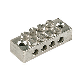
                                        Don't overcrowd the earth terminal : one big wire with an eyelet is best. The problem is dealt with by an earth block like this example from Screwfix:

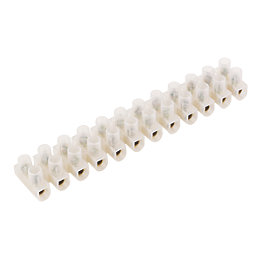
                                        Ideally the block is bolted to the metalwork near the VFD, but it can be free-standing. The main requirement of earthing is that all connections be secure – you don't want earth wires vibrating off an overcrowded terminal screw. Insulated terminal blocks are available too:

                                        ABS if you must, but metal cases are stronger, fireproof, and shield Radio Frequency emissions. An unfiltered, unshielded VFD is a potent source of electrical filth. Putting the VFD inside an earthed metal box helps contain its anti-social output.

                                        Dave

                                        #658282
                                        Chris152
                                        Participant
                                          @chris152

                                          Aha, I'd not seen an earthing block before. All clear.

                                          Would the correct thing now be to remove all the connections from the inverter and recut them, leaving extended earth cables and the other cables normal length, allowing the earths to connect to the block/ enclosure?

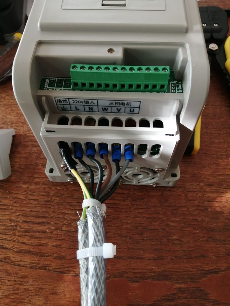
                                          It'd be easier if I could post pics when trying to explain things – do I need to find a photo hosting site and put them there, then link to them from here in my posts? I'm sure there's a guide somewhere on here, I'll take a look now.

                                          Thanks.

                                          #658285
                                          Chris152
                                          Participant
                                            @chris152

                                            Got it!

                                            img_20230828_104652.jpg

                                            #658298
                                            Emgee
                                            Participant
                                              @emgee

                                              If you are going to earth the cable screens at the VFD you need to use the correct earth bonded gland or other suitable arrangement.

                                              Emgee

                                              #658301
                                              Chris152
                                              Participant
                                                @chris152

                                                I didn't even think of earthing the screen wiring. I've just searched earthing gland and see it can be an earth tag or gland – presumably this connects to the same earthing block that will be attached to the metal wall enclosure, and that the cable earths attach to before connecting to the inverter?

                                                Thanks for pointing this out.

                                                #658304
                                                Robert Atkinson 2
                                                Participant
                                                  @robertatkinson2

                                                  A metallic case also reduces interference. You can use an ABS box but you should fit the VFD and any filters onto a metallic plate that is then installed in the ABS cox. All earths, includng cable screens / armour, should be connected as directly as possible to the plate.
                                                  With plastic box the best way to cround the screen is with a metallic clamp. You need 360 degree contact. Even an inch or two of tail reduces the effectiveness of the screen.
                                                  If your VFD does not explictly have an EMC filter you should fit one. it also needs to be mounted on the plate.

                                                  Ther are two disadvantages to putting the E-Stop in series with the normal stop input:
                                                  1/ The machine will not stop as quickly.
                                                  2/ if ther is a fault in the normal stop circuit the E-Stop won't work either.

                                                  Robert.

                                                  #658307
                                                  duncan webster 1
                                                  Participant
                                                    @duncanwebster1

                                                    Mine stops more quickly using the normal stop as that brakes the motor electrically. Using the Estop to cut all power means that it will stop no matter what the fault.

                                                    #658309
                                                    Chris152
                                                    Participant
                                                      @chris152

                                                      I'm now more or less decided we'll use a metal box.

                                                      Concerning EMC filter – the description of the inverter states:

                                                      "PWM CONTROL:
                                                      By optimizing PWM control technology and electromagnetic compatibility, it satisfies users' requirement of low noise, low electromagnetic interference."

                                                      Under the specs, it says "Filter – Fitted", but it doesn't specify what kind of filter.

                                                      Is that sufficient to control EMC or should I fit a filter?

                                                      Thanks.

                                                      Edited By Chris152 on 28/08/2023 15:18:34

                                                    Viewing 25 posts - 26 through 50 (of 84 total)
                                                    • Please log in to reply to this topic. Registering is free and easy using the links on the menu at the top of this page.

                                                    Advert

                                                    Latest Replies

                                                    Viewing 25 topics - 1 through 25 (of 25 total)
                                                    Viewing 25 topics - 1 through 25 (of 25 total)

                                                    View full reply list.

                                                    Advert

                                                    Newsletter Sign-up