2 Cylinder Muncaster Steam Engine

Advert

2 Cylinder Muncaster Steam Engine

Home Forums Stationary engines 2 Cylinder Muncaster Steam Engine

Viewing 5 posts - 1 through 5 (of 5 total)
  • Author
    Posts
  • #616168
    Paul Lousick
    Participant
      @paullousick59116

      I plan to build a 2 cylinder Antablature Steam Engine by Muncaster and like most projects, model it in CAD first to identify any design problems in the drawings.

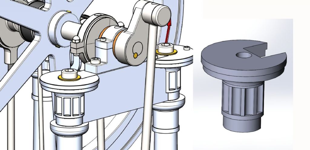
      Modelling the special feature at the top of the support columns is not a problem in CAD as shown, but how would you machine the circular cut-outs that have a square corner at each end ? Even casting would have a problem withdrawing the pattern from a mold (unless lost wax).

      An option is to make it in 2 pieces and plunge cut the grooves from the end and then join the top to the bottom.

      Any other ideas ?

      muncaster column.jpg

      column detail.jpg

      Advert
      #3501
      Paul Lousick
      Participant
        @paullousick59116
        #616169
        Jeff Dayman
        Participant
          @jeffdayman43397

          Ah, Mr De Waal strikes again!

          If the flutes are a must I'd say splitting the part into two disk based shapes and a fluted drum between them would be easiest. If radii were allowable at the ends of the flutes they could be made with miniature ballnose endmills leaving the part one piece. The flutes could be made by EDM of course, with flat ends or radiused ends (or flat ends with 3-5 degree casting draft, for authenticity to real cast parts on the original engine).

          But…

          The easiest way by far to build the part would be to delete the flutes and say "the patternmakers was on strike M'Lord."

          Edited By Jeff Dayman on 06/10/2022 03:13:02

          #616170
          Paul Lousick
          Participant
            @paullousick59116

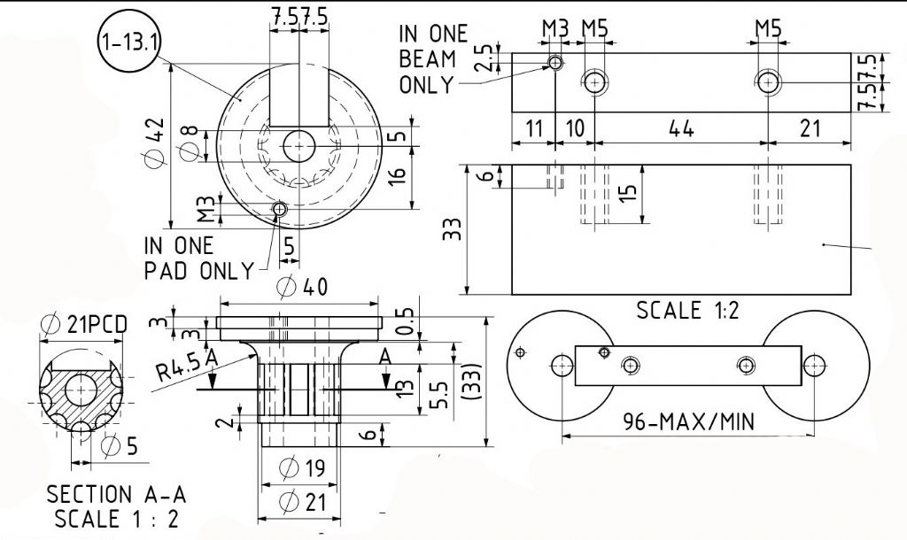
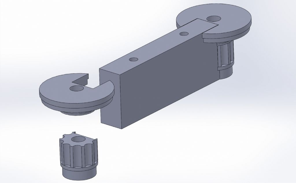
            I like the comment "the patternmakers was on strike M'Lord." but I like the feature and will make the part in 2 pieces. I also have to join the flat member between the 2 column ends and will make a jig to hold them while silver soldering.

            sa-1-103 exploded.jpg

            There are lots of Muncaster model engine drawings for downloading, but I wonder how many have actually been made by the author ? Details are crowded onto the drawing sheets, some of which are not presented in an orderly way.

            Dimensions are chain linked and not referenced to a common datum which can result in an accumulation of tolerance errors. (Mating parts may not line up exactly). If I were to present drawings like this to our machine shop they would be rejected and I would be looking for a new job. (should'nt colmplain though, they are free)

            #616172
            JasonB
            Moderator
              @jasonb

              A lot of models build up the bases and capitals for several parts, even the small simple entablature based on Muncaster's design that I made had two pieces top and bottom.

              So ,ake from ,ore than one piece and either plunge as said or have a separate disc at the bottom then you could mill with a ball nose cutter or a single point tool much like cutting a gear

              On a part like that I would make the components so the assembly is over height and without the two holes for the columns and once soldered bring to height and add the holes so there is not risk of problems if things move during soldering

              I hope you won't be using the cap head screws he shows but leaving a spigot on the column to take a nut. There are other features that don't look right on Julius's version for example all that detail in the entablature and he sticks a simple big end on the conrod that would be more at home on a wobbler. I also feel that the large round top of the part in question should actually be square as you could not mount the governor that Muncaster shows on a round surface, infact most of that detail above the taper of the column should be square. Take a look at Muncaster's original illustrations and decide what you want to make.

              Julius does not build any of hose engines. Do check for collisions as the grasshopped that he drew had a tight spot when motion was simulated due to the length of the linkages being wrong. I would not have been happy with his solution to just make one of the holes oversize, although it allowed the engine to be turned over on screen the CAD did not replicate the knocking that the oversize hole and small pin would cause.

              Unusual for Julius to make an engine smaller than Muncaster originally drew it but he has on this one, probably trying to keep the flywheel so it fits on a few more lathes as 10" would have put it beyond Myford gap capacity.


              Edited By JasonB on 06/10/2022 08:43:10

            Viewing 5 posts - 1 through 5 (of 5 total)
            • Please log in to reply to this topic. Registering is free and easy using the links on the menu at the top of this page.

            Advert

            Latest Replies

            Home Forums Stationary engines Topics

            Viewing 25 topics - 1 through 25 (of 25 total)
            Viewing 25 topics - 1 through 25 (of 25 total)

            View full reply list.

            Advert

            Newsletter Sign-up