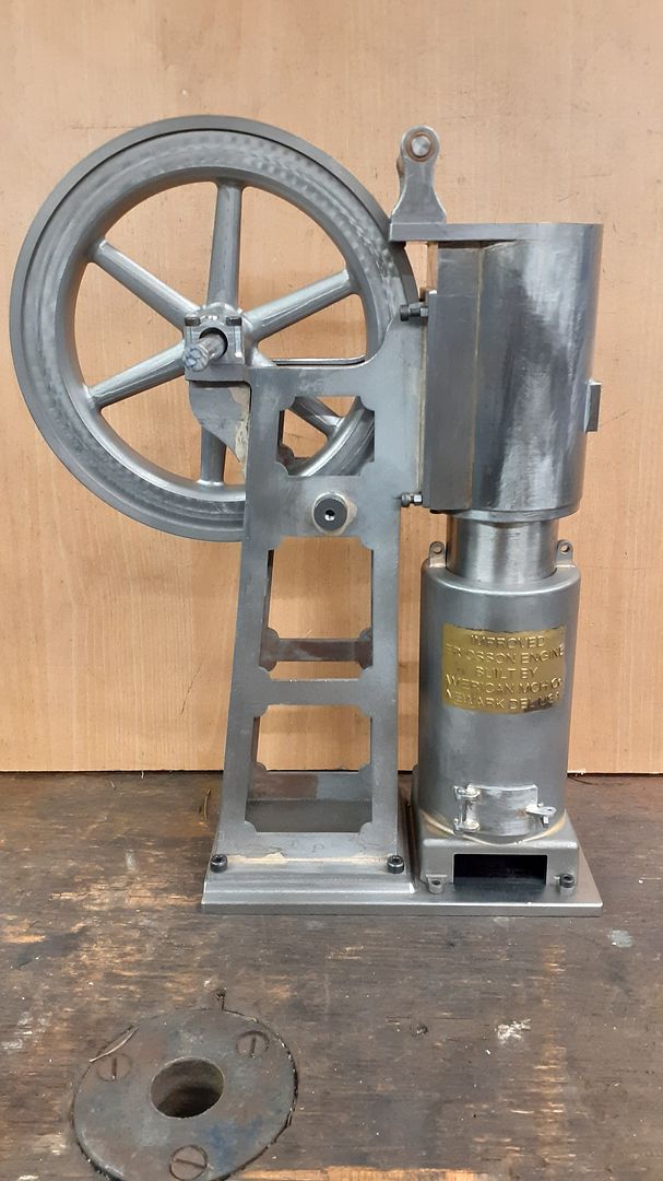
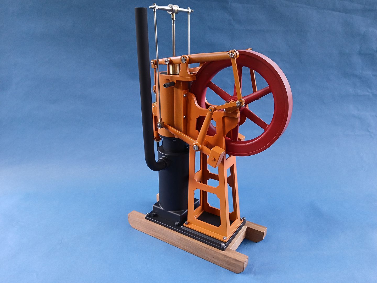
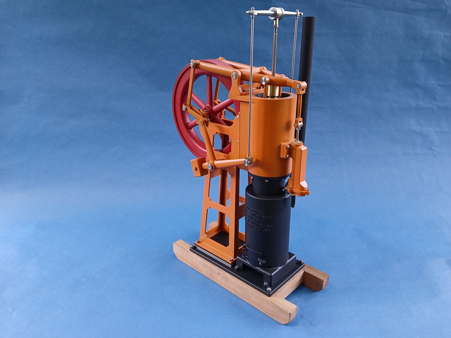
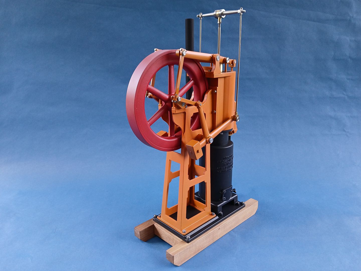
Most people seem to opt for building the Rider Ericsson Engine with it’s four legged “table and furnace slung below but I have always liked the look of the Denny Improved version. There is the Eisner kit available for one in 1/4 Scale but I have read of issues with the design and castings. I did get a look at the drawings for this and could see some obvious issues of fit and when I did a basic layout of it in CAD there were other things I did not feel looked right.
So I decided to go back to basics and scanned in a patent drawing so that I could “trace” it in Alibre CAD and pull the sizes directly off of that. This shows one of 5 sets of dimensions that were taken from the patent once it had been scaled to my chosen size which is a 40mm bore making the model approx 1/5th scale, this also kept the flywheel within the XY envelope of my CNC so I could cut that from a slice of cast iron bar.
I initially just drew the various rods and linkages as simple flat bars with holes at the pivot points and did a trial assembly to check how everything moved and once happy with that set about detailing the various parts that would all be fabricated or cut from solid. I found that setting them to 50% transparency and then assembling over the Patent drawing also made checking the proportions easy, sectioning the parts also made sure nothing was going to clash internally
A quick check of what materials I had in stock and what needed to be ordered and this lot arrived a couple of days later from M-machine, the main items are some flat black bar for the base plate, slice of CI for flywheel, Brass tube for displacer (did not use it) and some thick wall steel tube that will become both Furnace and Cylinder Jacket and a piece of 70mm square for the furnace base.
After marinading in brick cleaning acid to remove the mill scale the piece of flat black bar for the base was cut a little oversize and then various holes drilled and tapped.
I then made use of the tapped holes to mount the base to a machining plate and used the CNC to bring it to the correct overall size with rounded corners and also reduce the thickness where the furnace sits. I roughed this out with an adaptive path using a 6mm flat-ended cutter then finished with another 6mm cutter but this time with a 1mm radius corner which left a small fillet where the angled edge to the raised section meets the flat. and using a 0.2mm scallop between passes the angled slope will need little in the way of hand finishing to get it paint ready.
It’s a water pump which is what these engines were typically used for, quite often pumping from a well or bore hole up into a storage cistern in the roof of a large house so there was water available at the taps under gravity flow.
It also doubled to keep the power cylinder cool as the water passes from the pump around the water jacket then off to it’s intended use. I was just using air to keep it cool in my video.
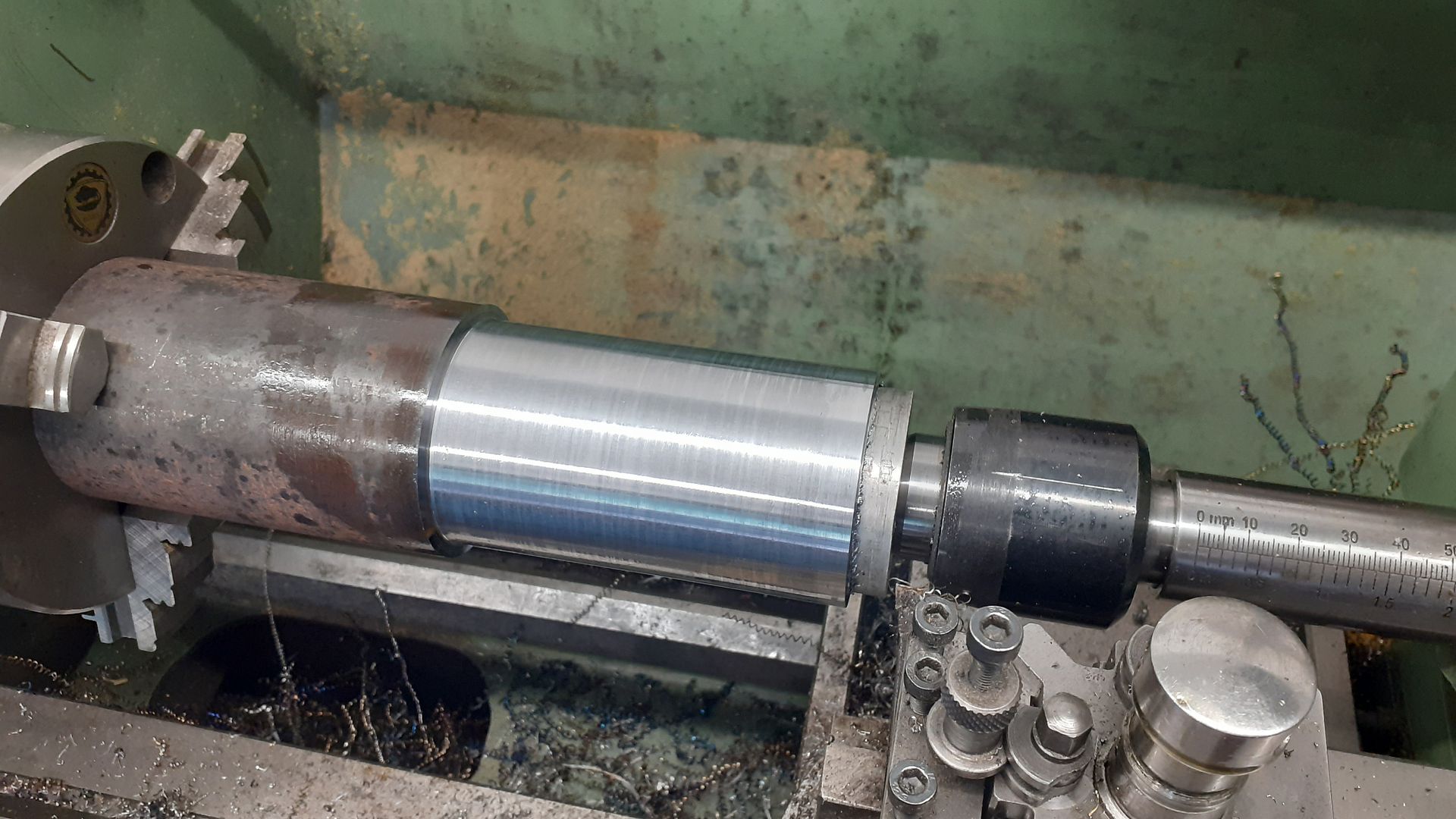
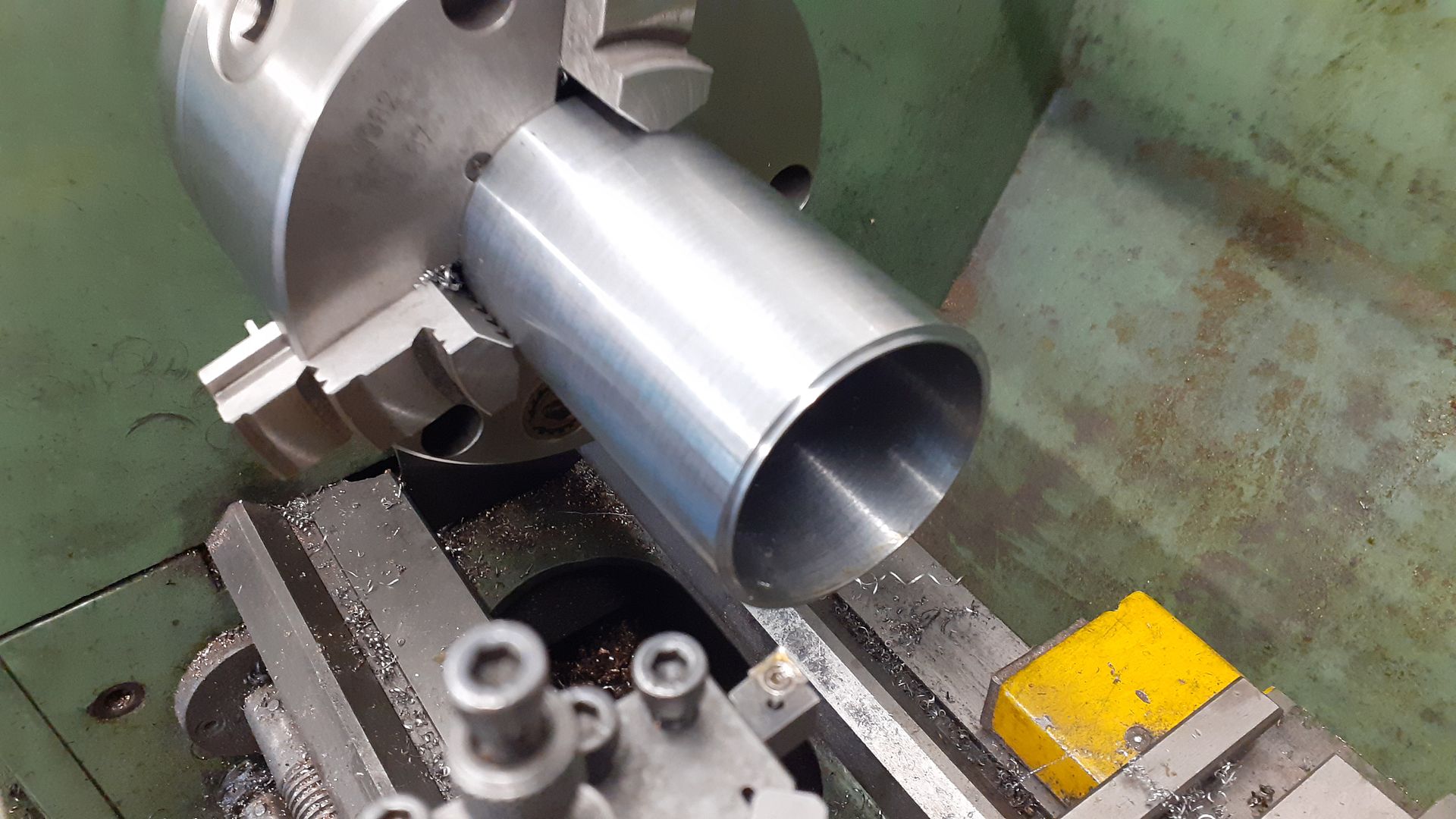
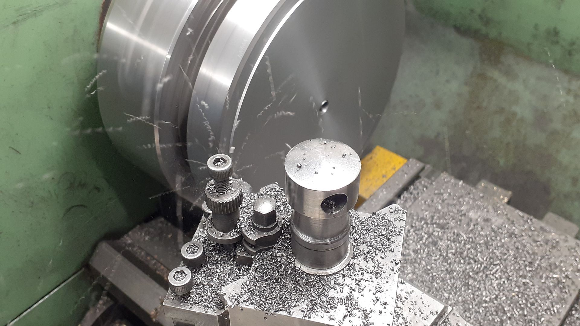
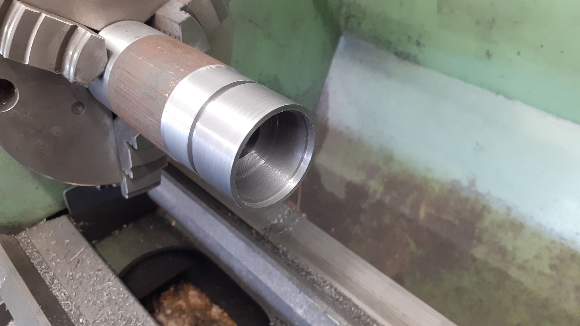
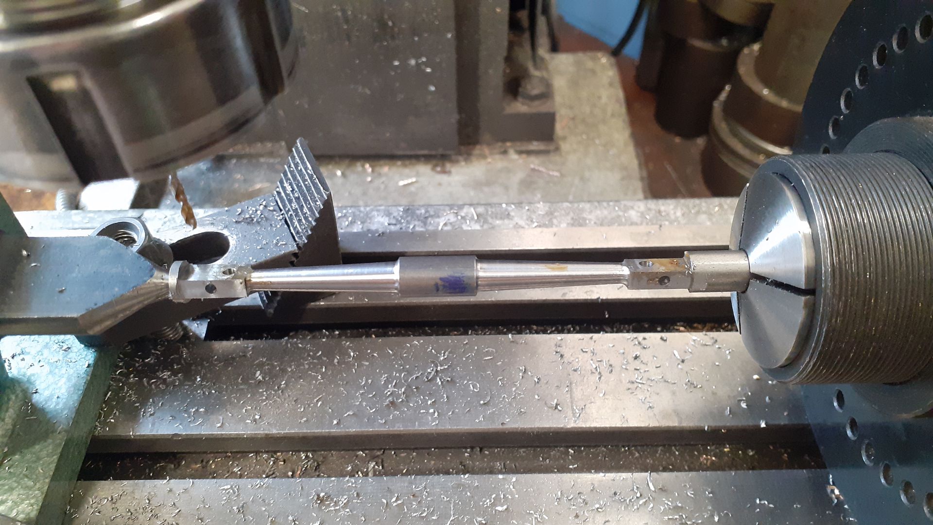
As the thick wall tube for the furnace and cylinder needed reducing in diameter and to save wasting material by leaving a chucking piece I made a bung for the end so I could turn sufficient length of the OD and then saw off the full length, here I’m doing the second piece having already turned and cut off the first,
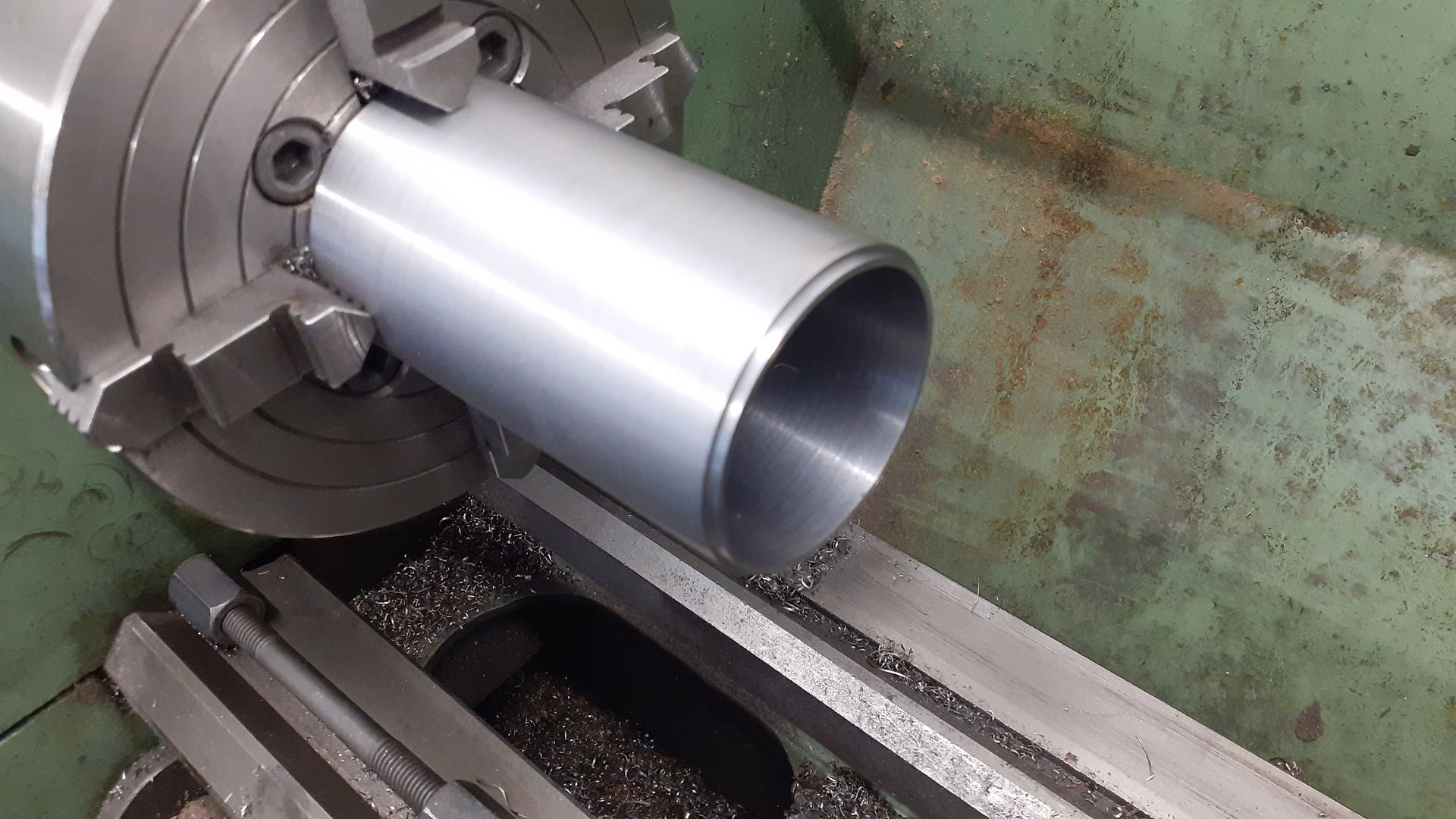
I could then hold the furnace part by the outside to bore out to the required diameter, face the end and cut a short spigot to locate it into the lower half.
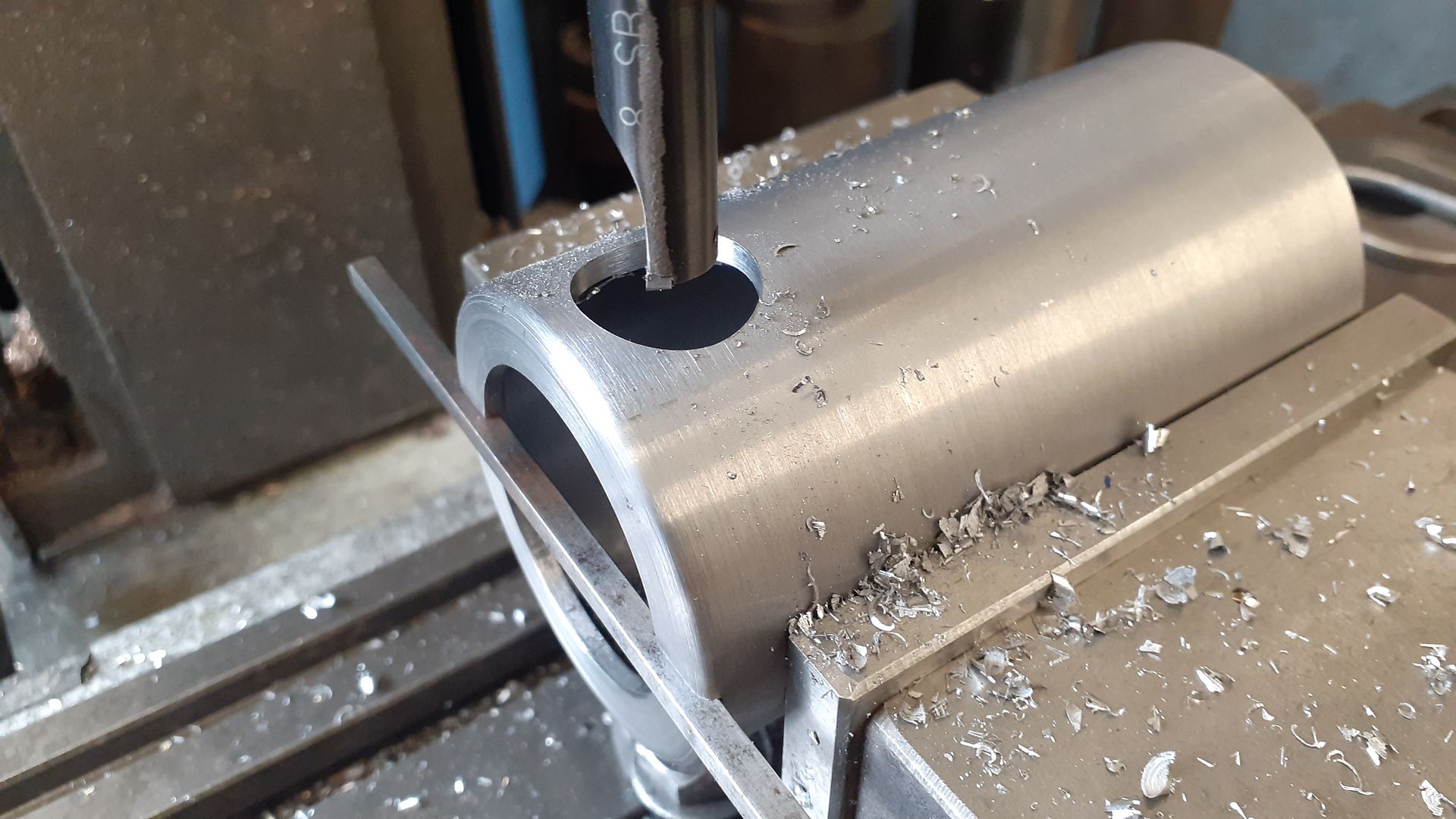
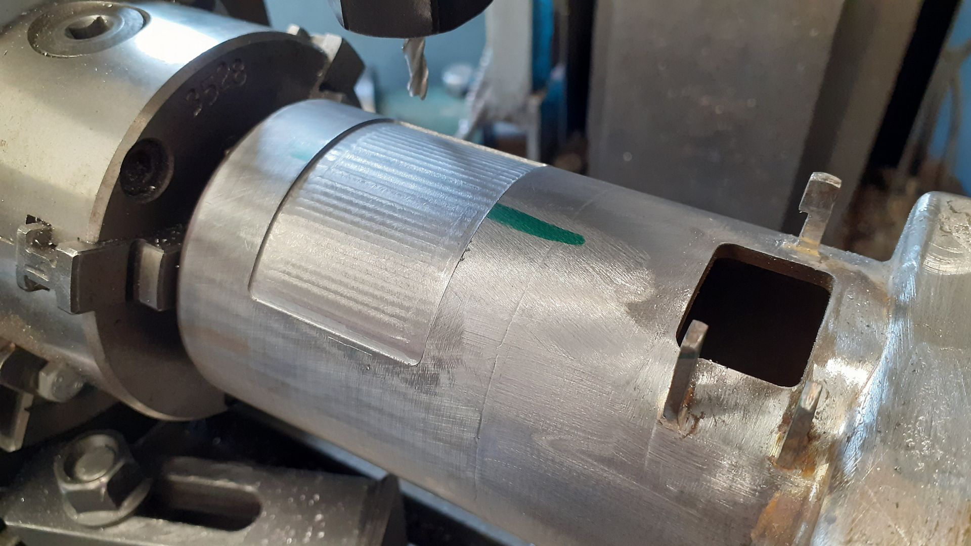
A 4mm wide slot was milled across the top for two lugs that will need to be soldere don and I then made use of the slot with a piece of key steel slipped into it so I could set the slot horizontally while I bored out the hole for the flue.
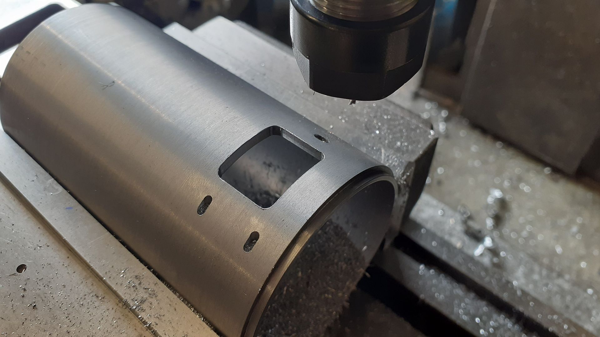
I then rotated it 180deg so that the fire door opening could be milled on the opposite side as well as some small pockets to locate the hinge and latch parts that would also be soldered into place.
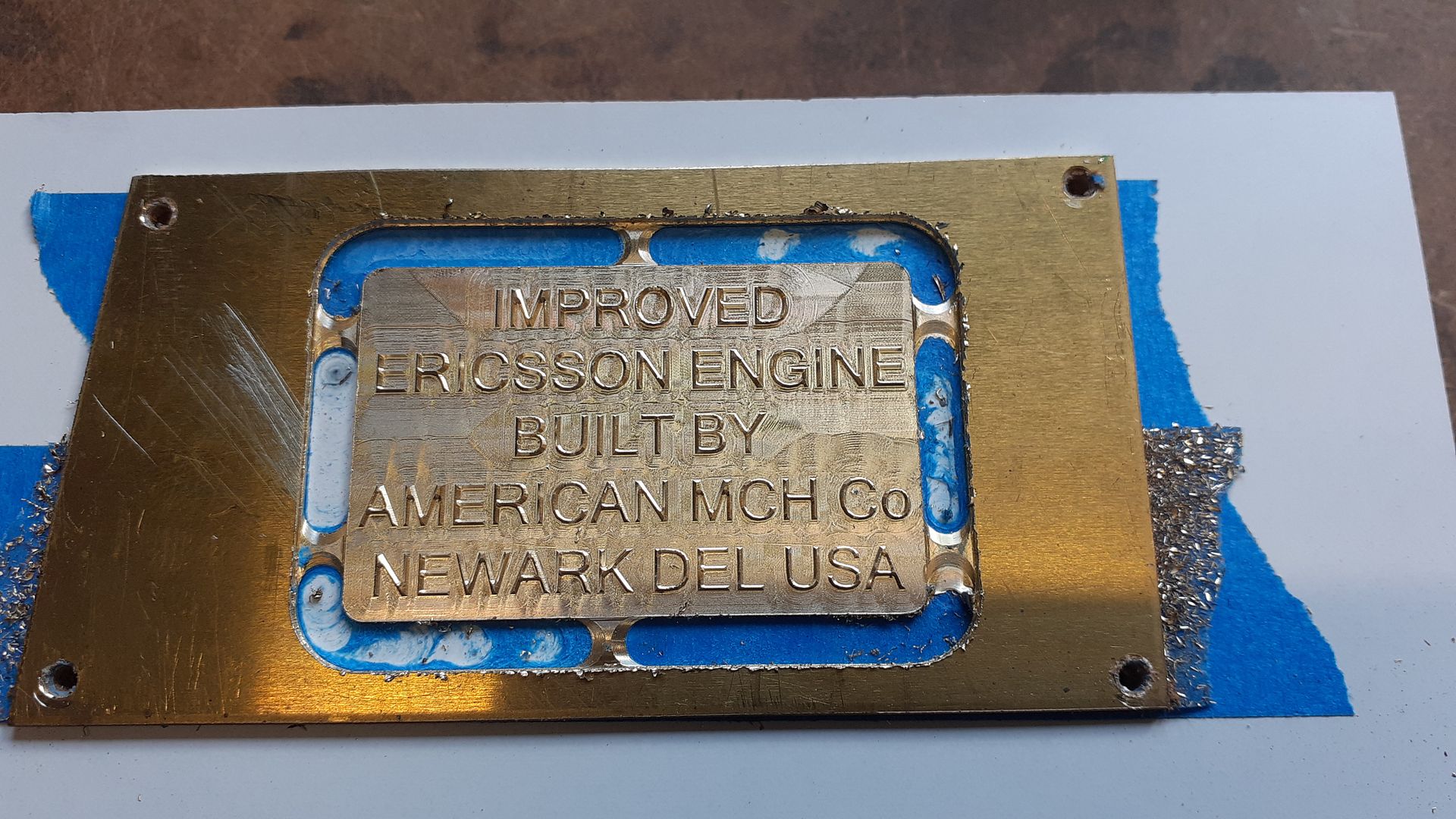
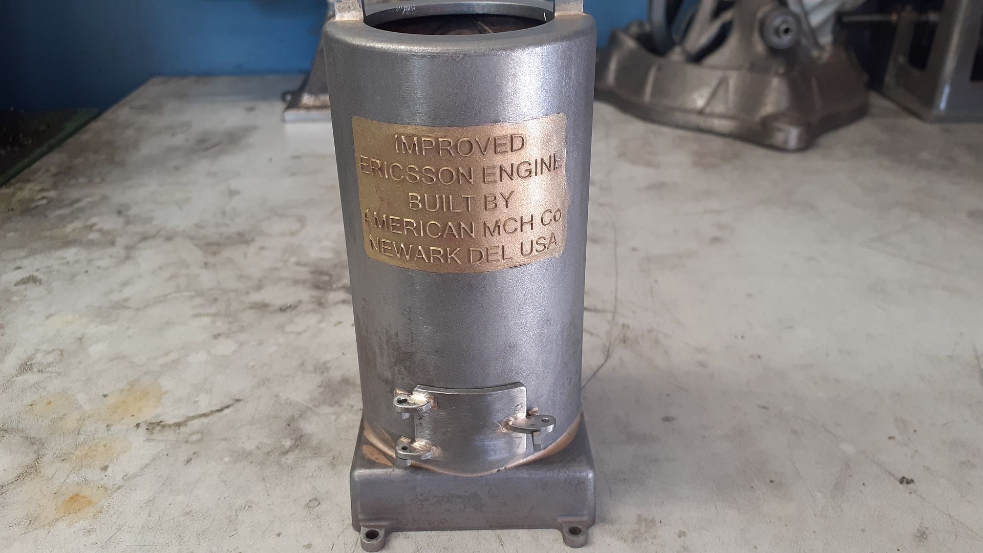
The furnace on these engines has quite a lot of wording cast into it and I was keen to replicate this so drew it out in CAD and used the CNC to mill away the surrounding metal to leave the letters standing proud, This took quite a while as the fine pointed engraving tool could only take a small stepover but it’s tapered end did replicate the cast letters draft angle.
The furnace body was then held on the rotary table so that a pocket could be milled into which the suitable bent lettering could be soldered
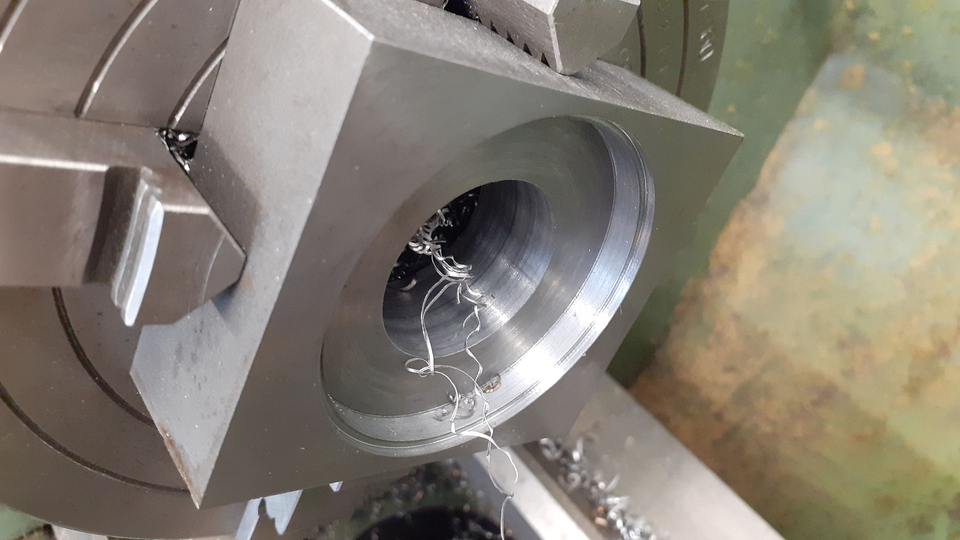
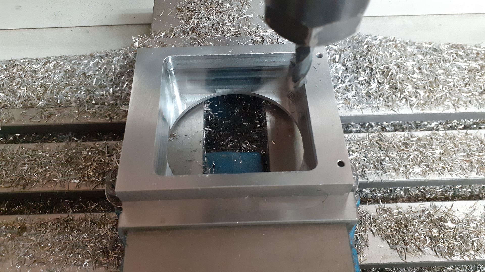
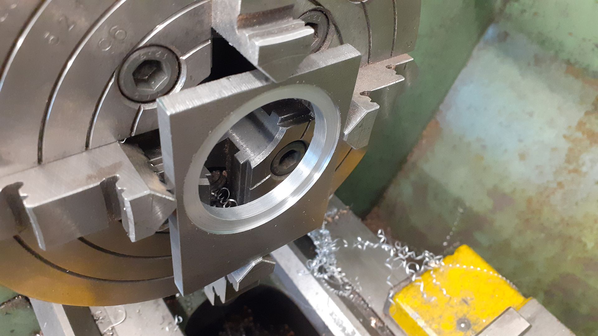
The lower part of the furnace was base from some square bar, first boring out the waste material and a step to locate the spigot of the top half.
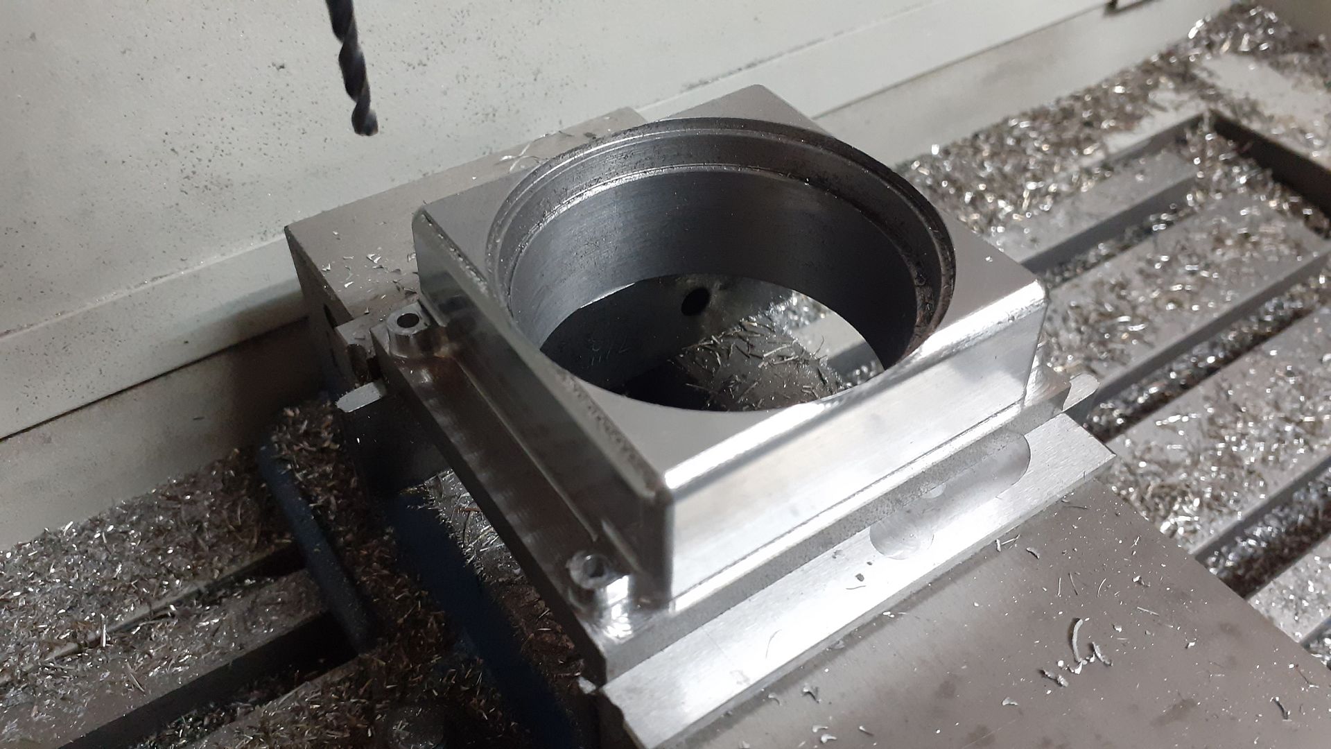
Then over to the CNC to cut the outside complete with draft angle to the sides and feet.
Then flipped the other way up to square up the cavity before milling off the excess depth.
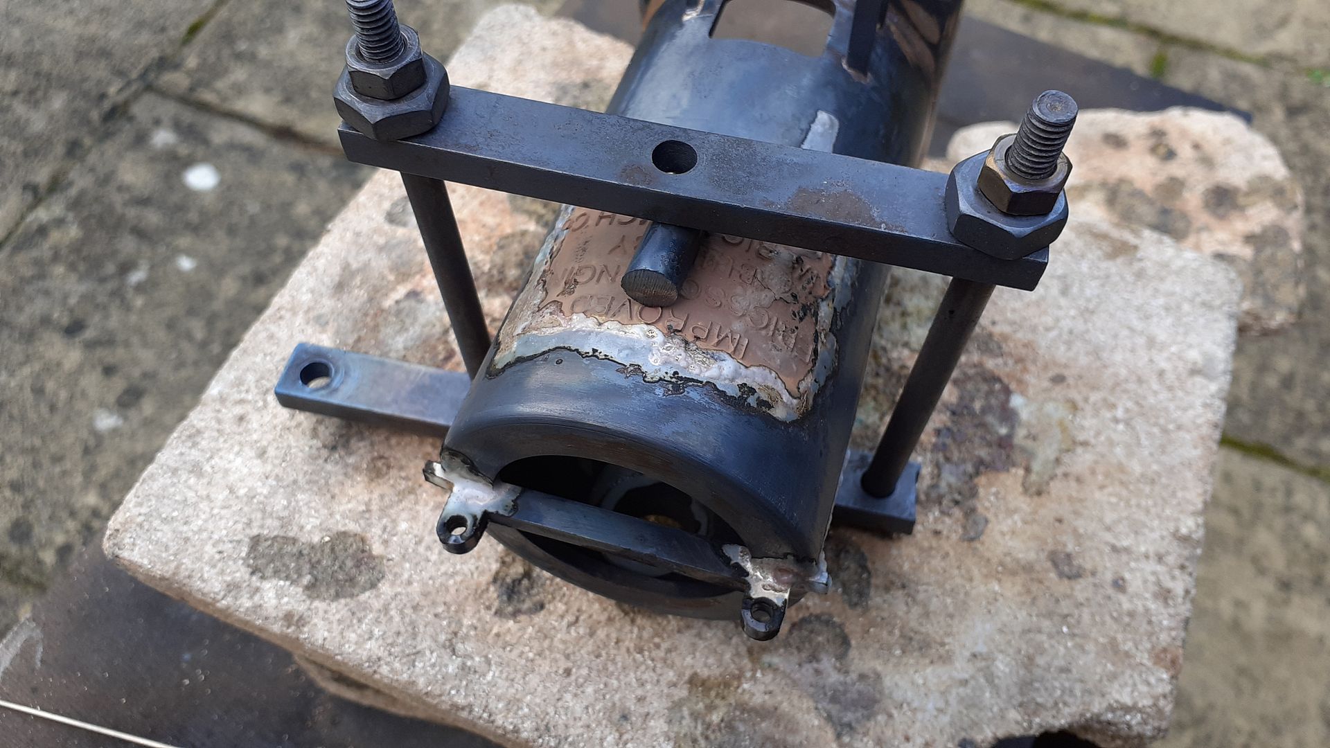
I used a Sif type rod to braze the two main halves and the hinge/latch parts together then after a quick pickle used silver solder to do the nameplate and top lugs.
After a clean up and grit blast and the addition of the door that’s about complete.
The water jacket started much like the furnace with the tube being held by it’s finished OD so it could be bored out but leaving a smaller diameter at the far end but a similar locating spigot at the top.
Some 5mm plate was bored out a little undersize and then a larger counterbore was machined to accommodate the spigot on the tube
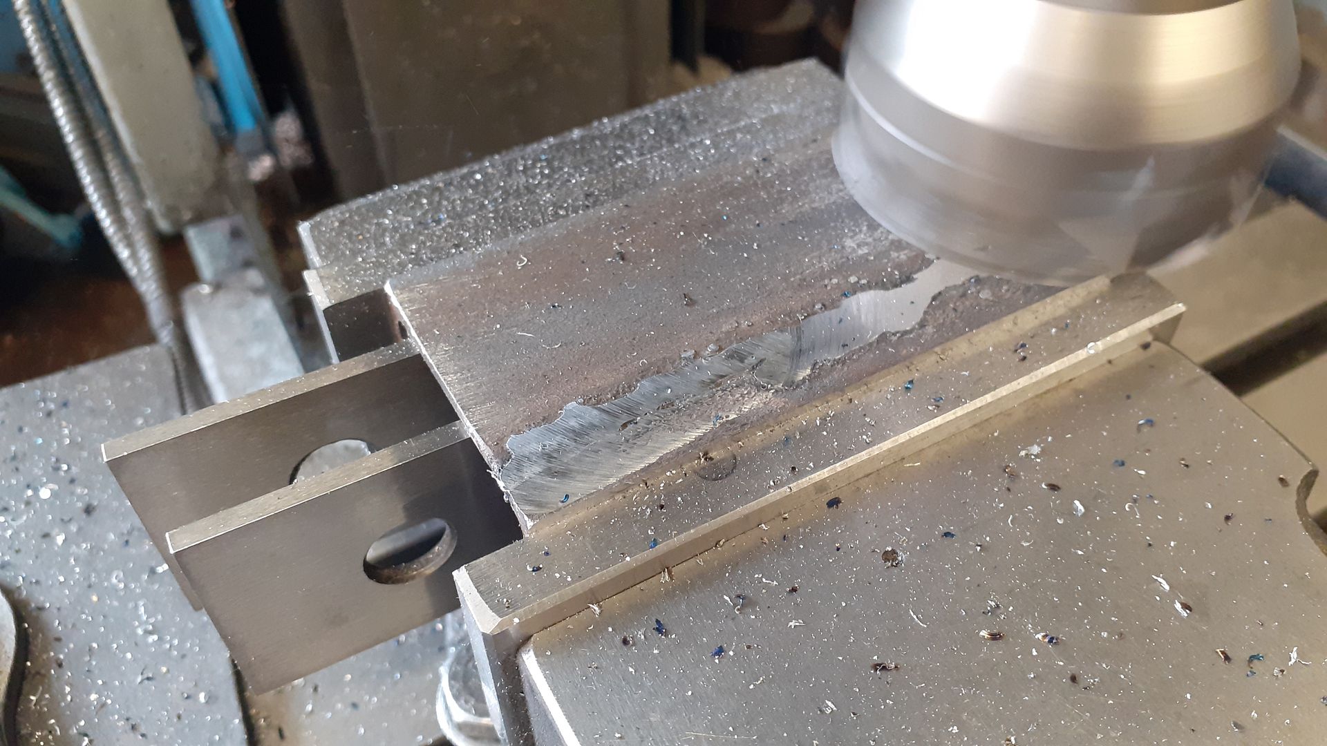
There is a flat down one side of the jacket and rather than cut this from solid which would have been a big lump to heat up for silver soldering I opted to weld two pieces of angle iron together. This shot shows the weld being machined flat though final machning will be done after soldering.
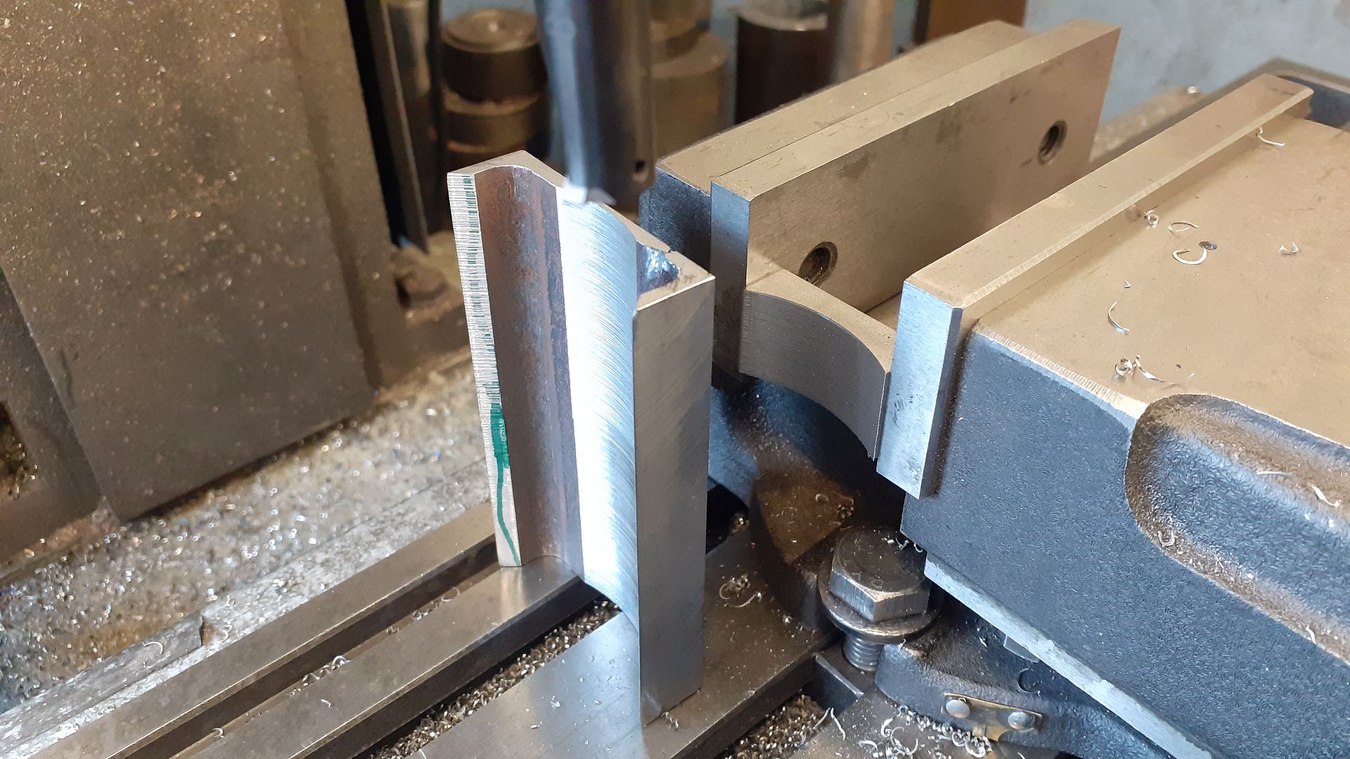
I then used the boring head to cut the other side to a curve to match the jacket, also did the block that the water pump fits to at the same setting.
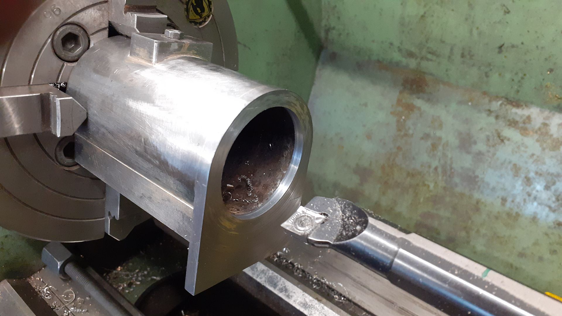
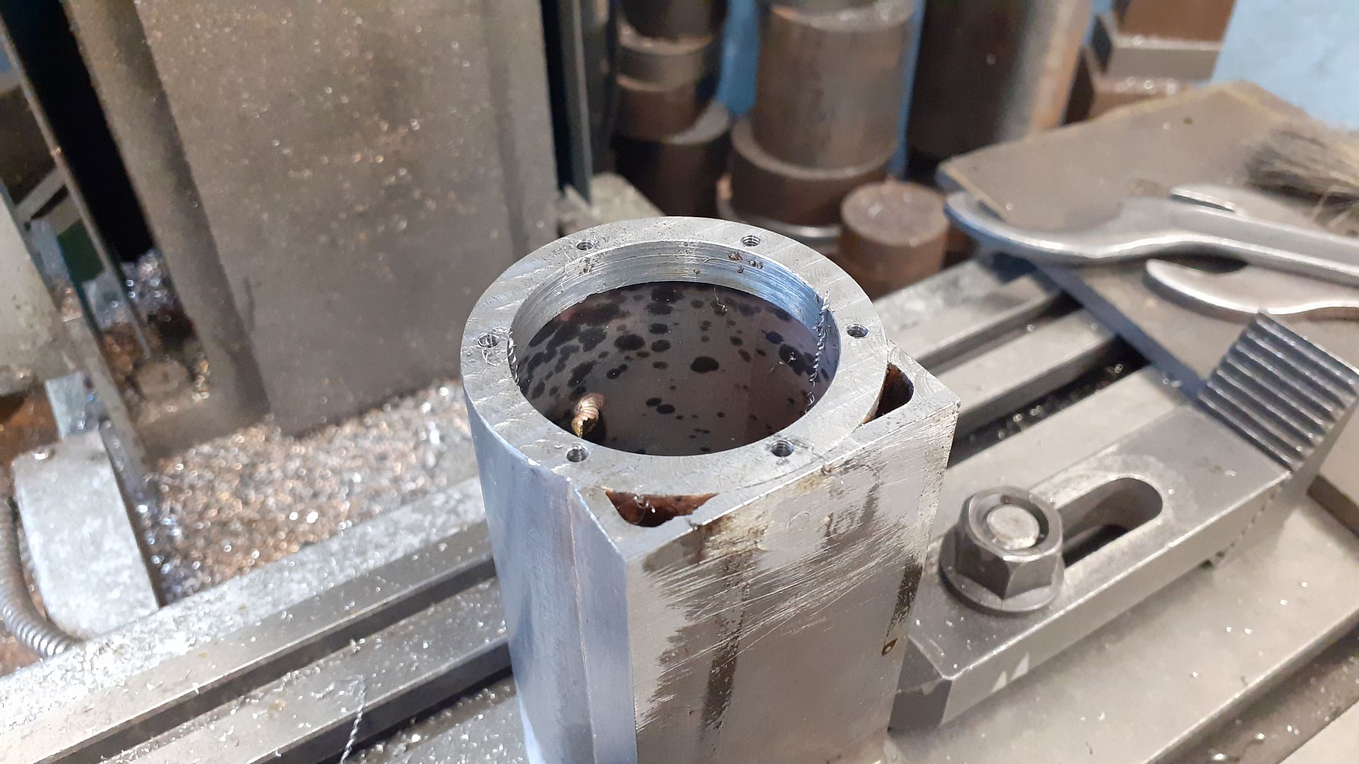
After soldering and a pickle the assembled parts were then treated much like you would a casting, here the top plate has been bored to size and the bottom end 0.2mm smaller so that the liner will drop in most of the way before it becomes tight. The plate was also faced to bring the overall length to finished size.
The bottom just needed drilling and tapping for some bolts that will hold the hot cap in place
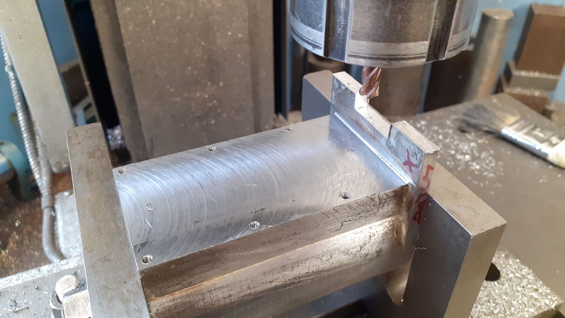
With the jacket firmly held between two angle plates the flat side was milled down to the correct offset from the ctr of the jacket, six holes tapped to attach it to the frame and I have just milled out the clearance slot for the flywheel with a 6mm cutter with 1mm corner radius to leave an internal fillet for that cast look.
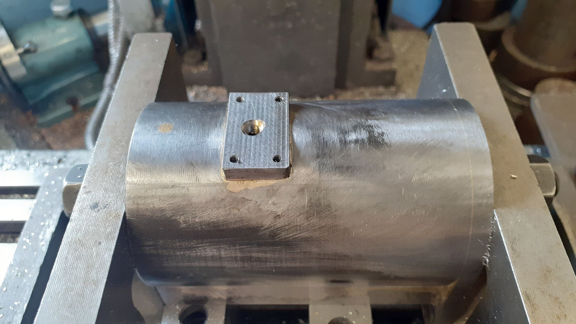
The block for the pump was also milled down to the final projection, drilled and tapped and the water passage was also drilled and counterbored for a sealing O ring.
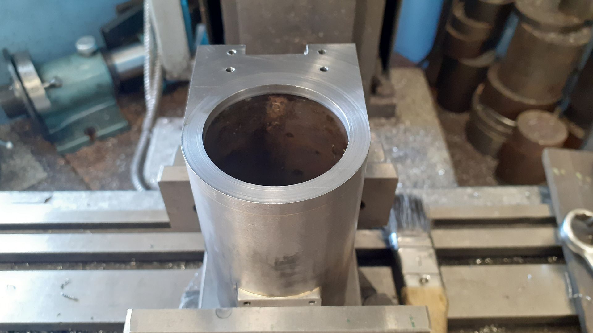
A bit more drilling and tapping on the top surface finishes the jacket off, this time they will hold the beam pivot bracket in place.
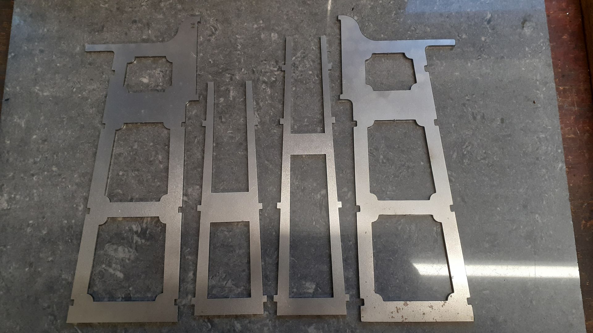
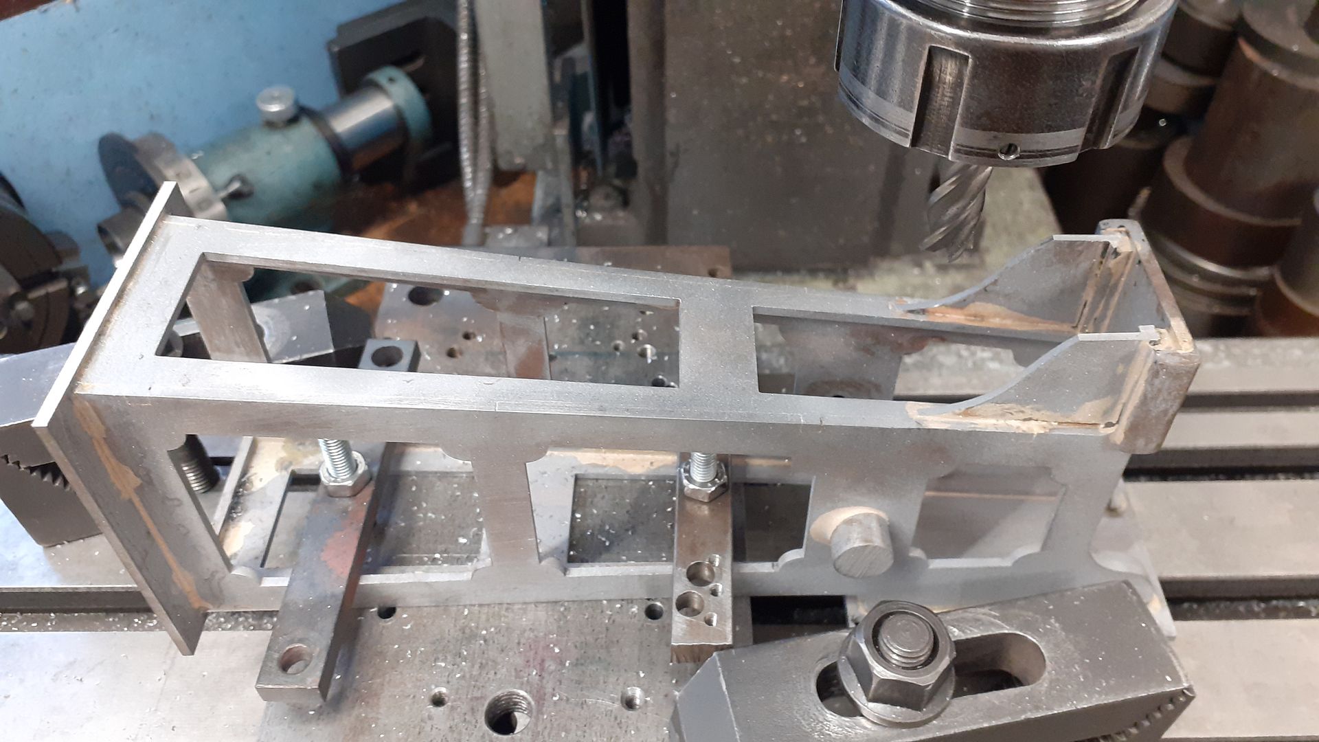
I was in two minds on how to make the “frame” structure that supports the flywheel and side levers – laser cutting would have got nice interernal corners but as I have the CNC that was also an option and I could always square up the corners with a file.
In the end I decided to use the CNC which did not work out as I had hoped, all was going well on the first piece then the swarf suddenly started to come off red hot with some sparks which took the edge off the carbide cutter but it carried on just throwing up a bit of a burr. The next time it came to the same part of the cut it was sparking again and then really struggled and broke soon after. Put in a new 3mm carbide cutter and it happened again. So looks like there was a hard inclusion in the 2.5mm steel sheet which I have had a couple of times before with steel.
Rather than buy some more 2.5mm sheet and replacement cutters I decided to produce the files and sent them off to Lasermasters who sent these back within a week.
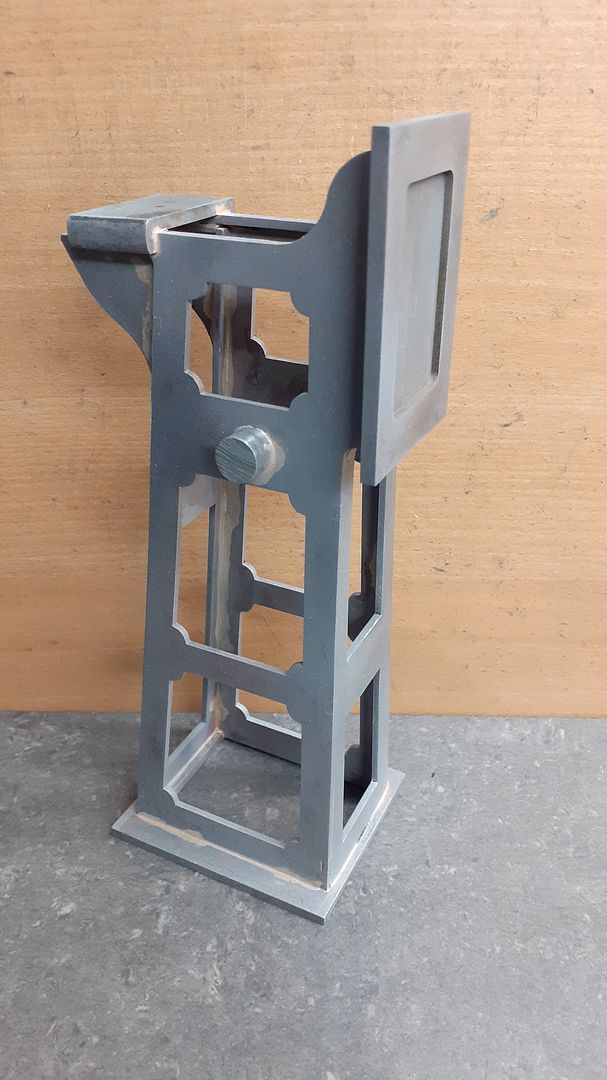
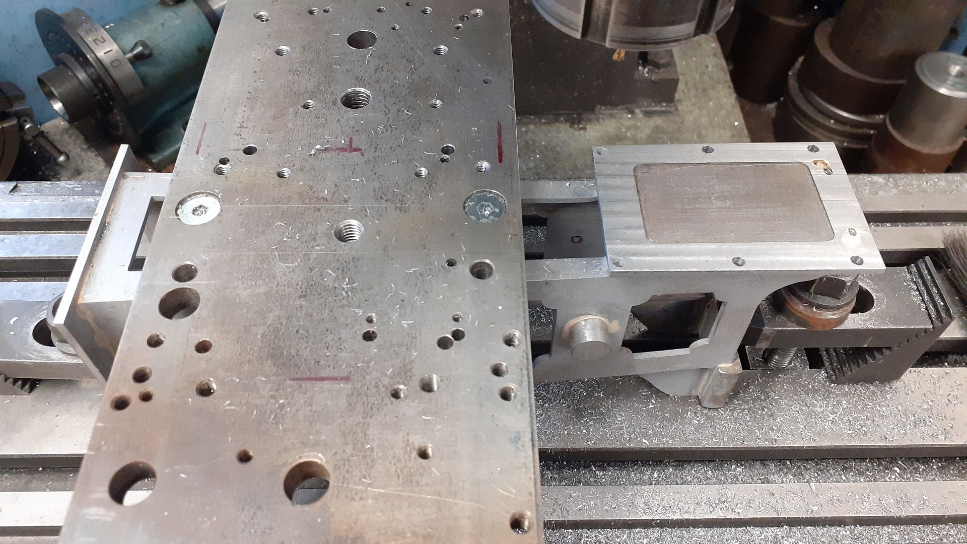
The base and vertical plate were milled up from 5mm sheet without incident as was a piece that will be machined to form the pads that the two bearing pedestals bolt to. These were then wired together and silver soldered.
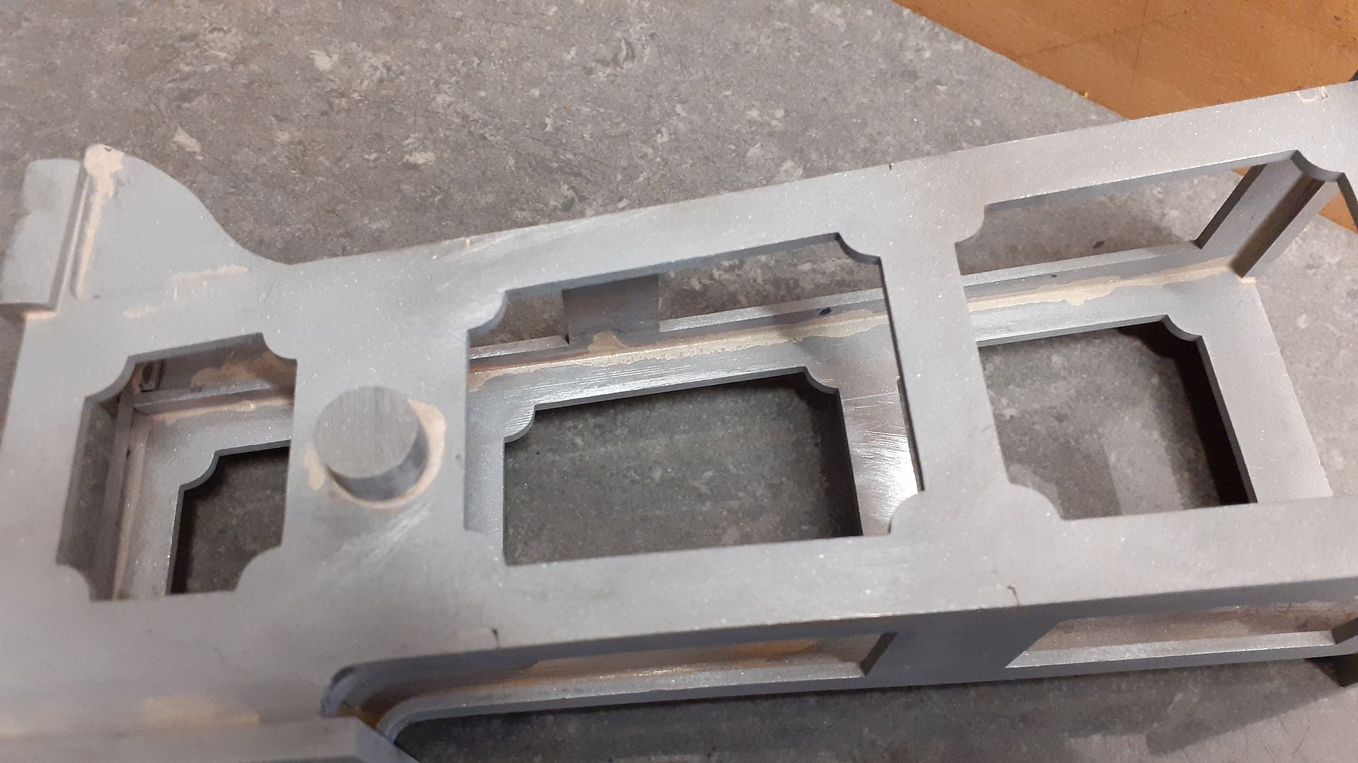
After a quick sand blast they cleaned up quite well with the solder having flowed well down the inside corners and out into the joint, just a few small gaps where the tabs did not completely fill the matching notch and the solder could not bridge the gap.
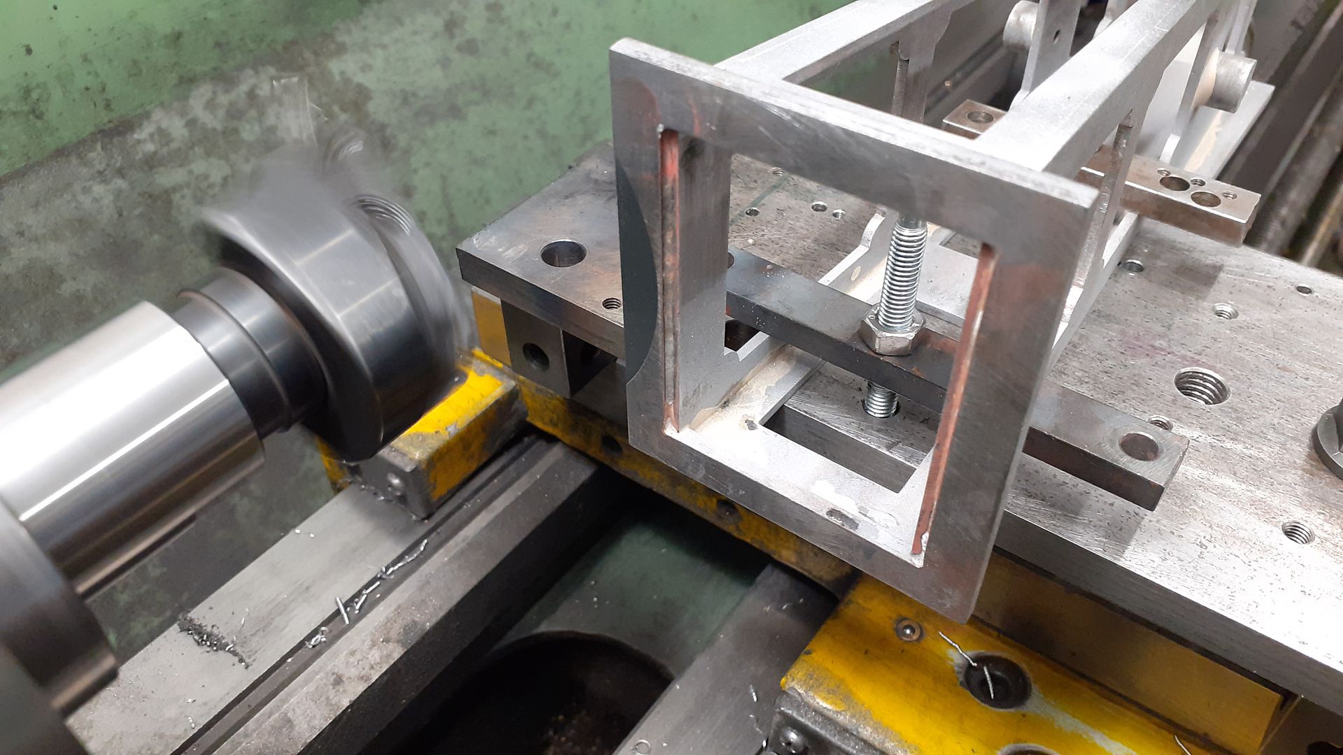
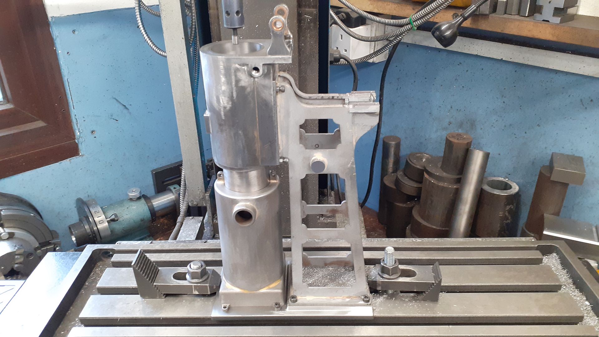
I could now start machining it so fixed it to a machining plate which was clamped to the lathe cross slide so the bottom that was left over thick could be cleaned up and brought down to the right thickness.
Then over to the mill to finish the edge of the base and I also skimmed the ends of the bearing supports to the same height (more to come off them later)
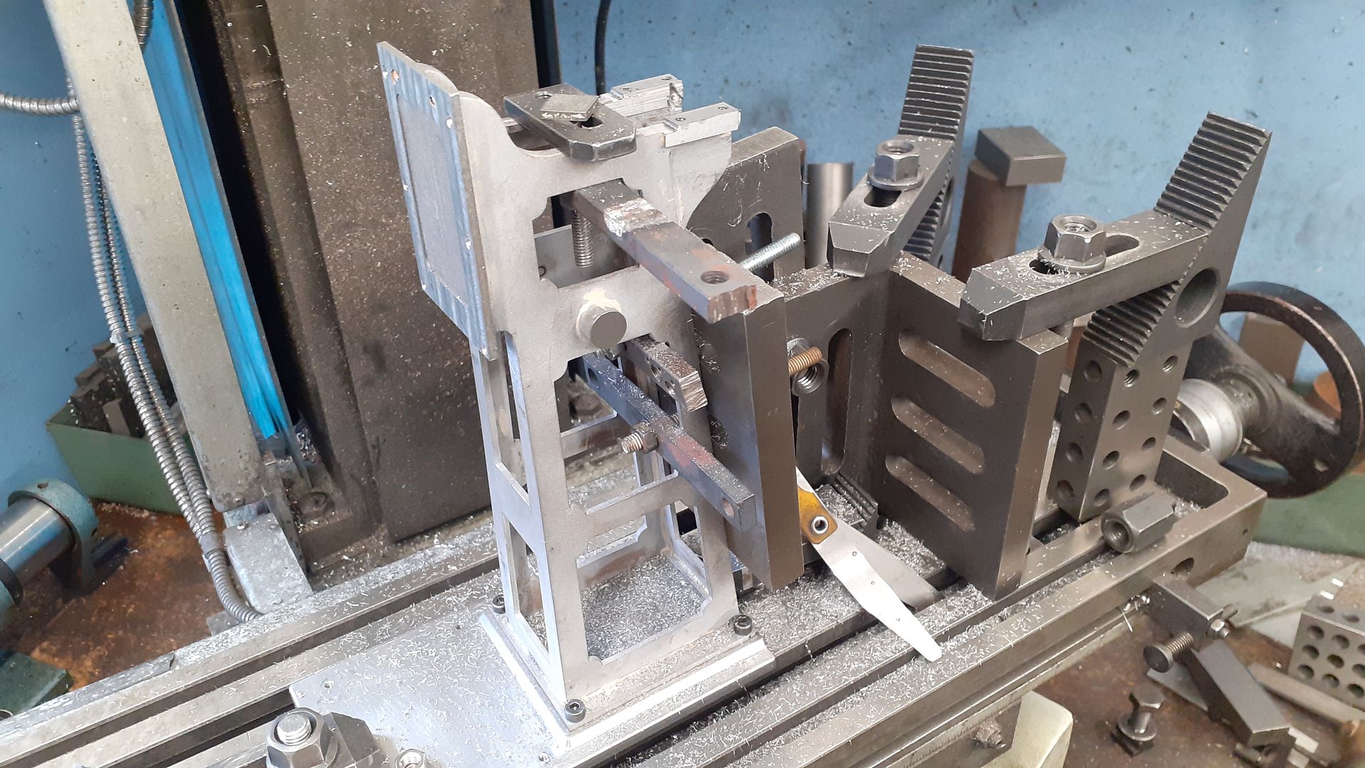
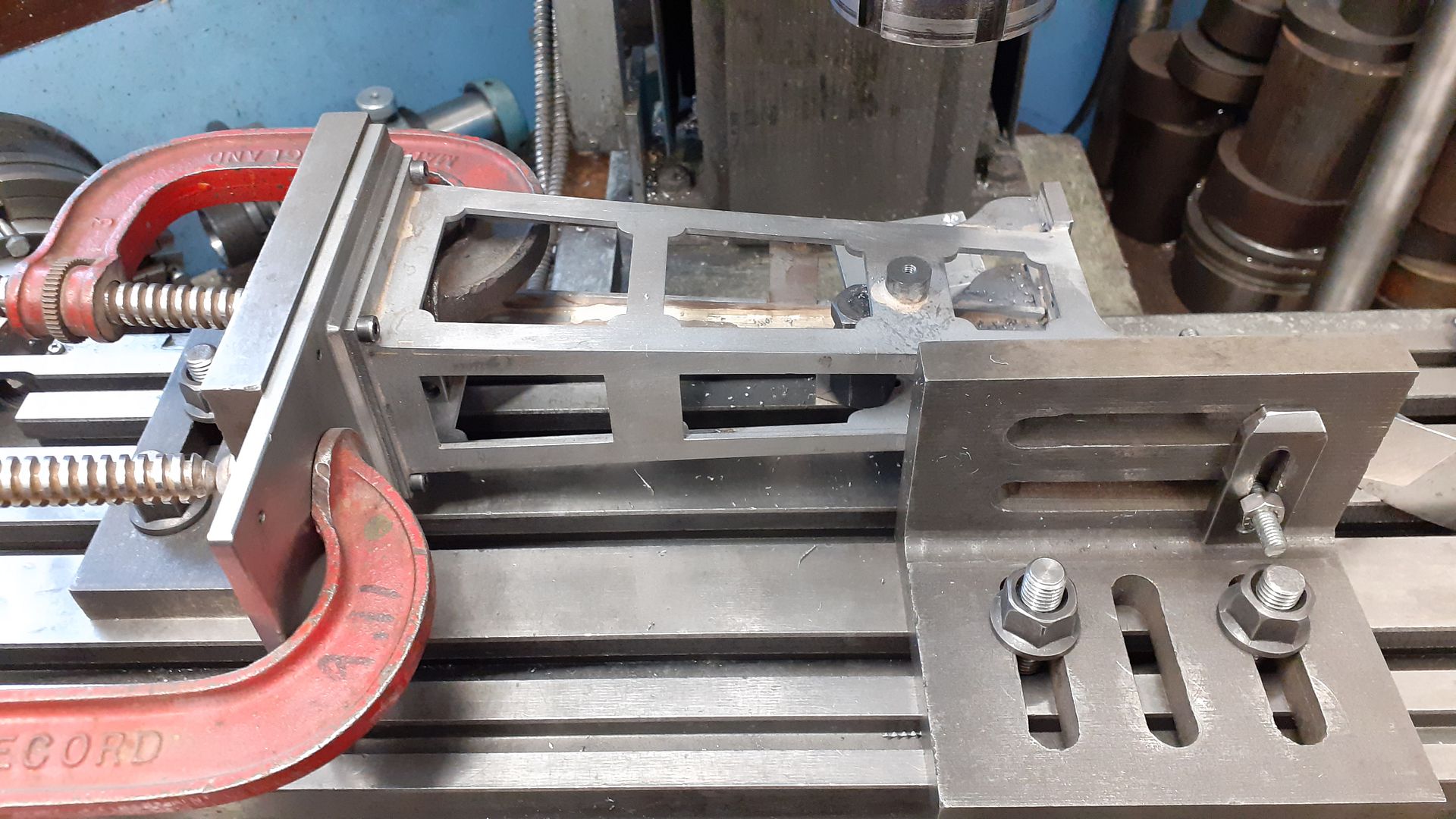
That gave me three points to sit on the mill table so the vertical plate could be milled square to the base as well as drilled & tapped.
The bearing supports were then milled to height and their ends trimmed to the final length as well as drilling and tapping for the pedestals.
Lastly the arm pivots were milled to length and drilled & tapped for the pivot pins.
The hot cap started life as a short length of stainless steel exhaust pipe which can be had in many different sizes on ebay. A disc of stainless sheet was Sif brazed to the bottom and a steel ring silver soldered to the top to form the mounting flange. After soldering the flange was skimmed down to final thickness ensuring it’s face was then true to the axis of the tube.
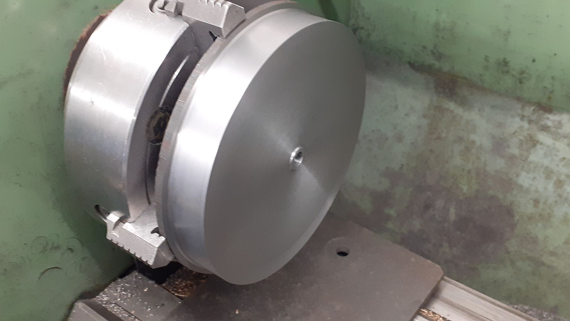
The flywheel was machined from a slice of 140mm diameter cast iron, here the first side has been faced, the OD finished and the hole bored for the crankshaft.
It was then reversed in the chuck, set to run true and brought down to final thickness.
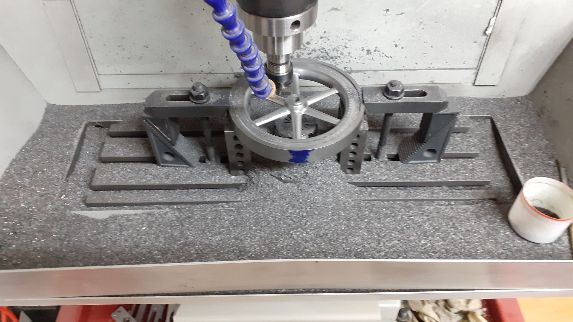
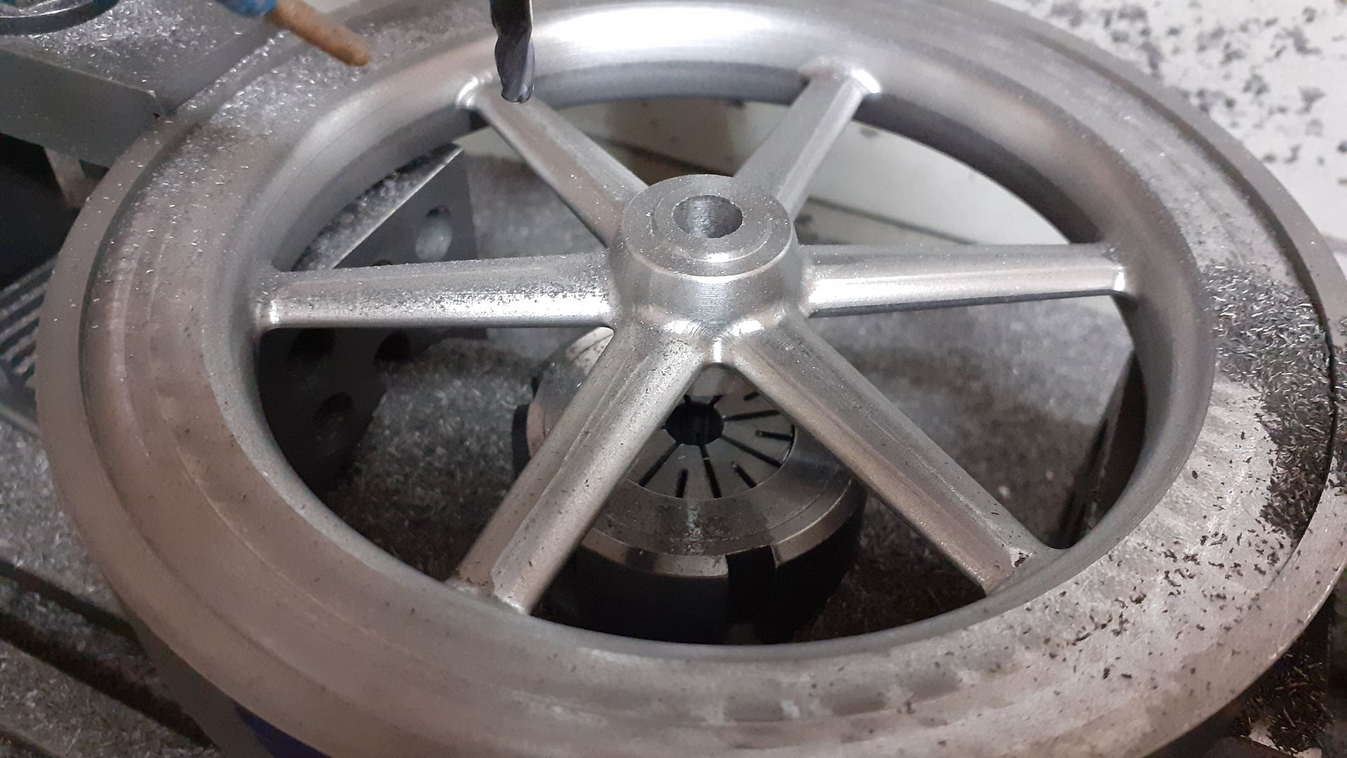
It was then over to the CNC to give it a bit of shape. I’ve done quite a few flywheels now and the method I have found to work the best is to mount the ER32 Collet with backplate onto the table and hold a piece of suitably sized drill rod in that which keeps the location of the ctr of the flywheel. I can then mill one side and flip it over to do the other and only need ensure that the rim of the flywheel lines up to a mark to index the rotation.
The flywheel is packed up on a couple of 1-2-3 blocks and clamped down. I use the clamps the opposite way round which reduces the height they stand up above the flywheel which means I can run shorter tool stick out with out risking the collet chuck hitting a clamp.
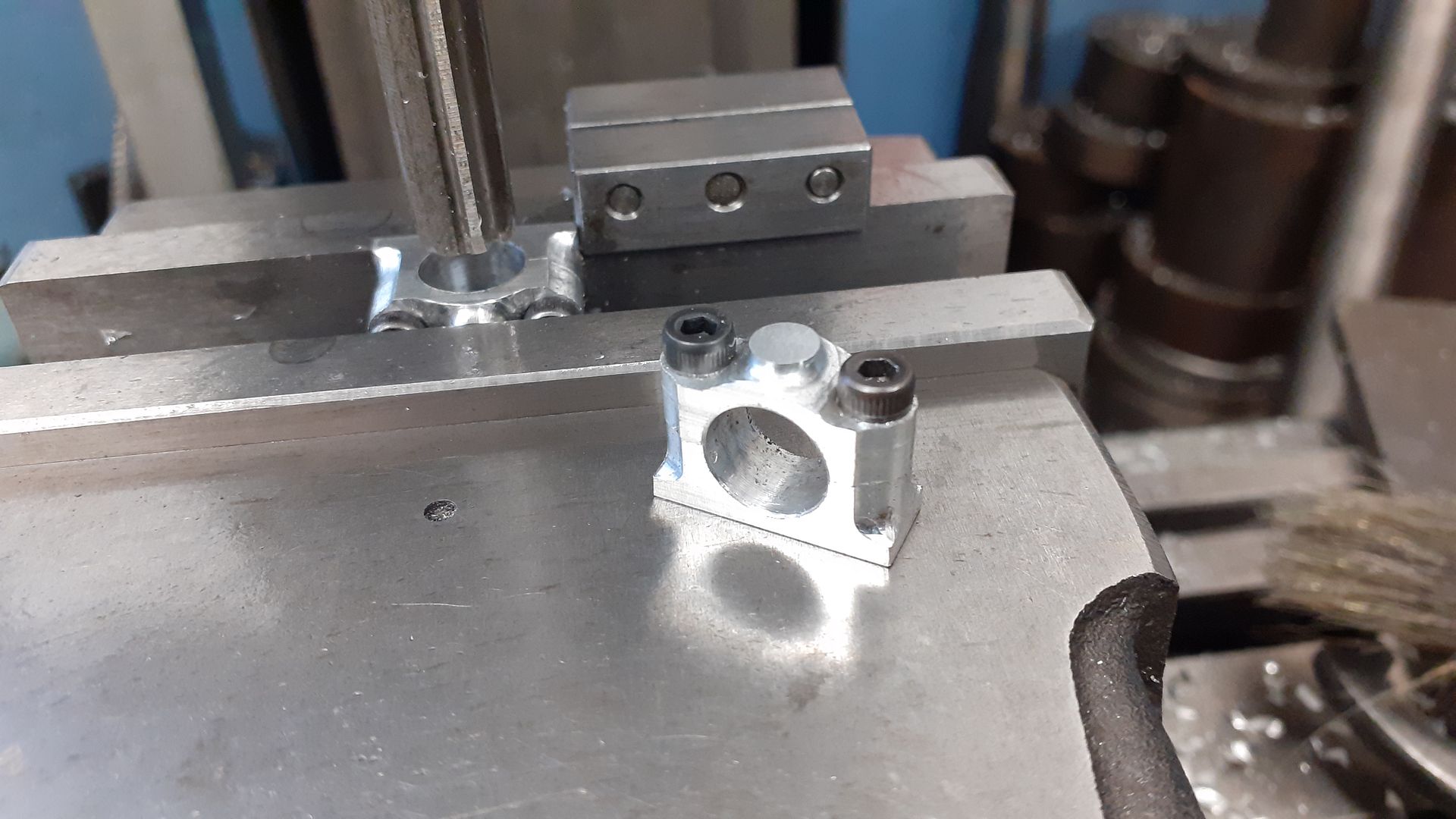
While I was at the CNC I machined the bearing pedestal tops and bottoms from aluminium Then screwed them together to drill and ream the holes on the manual mill
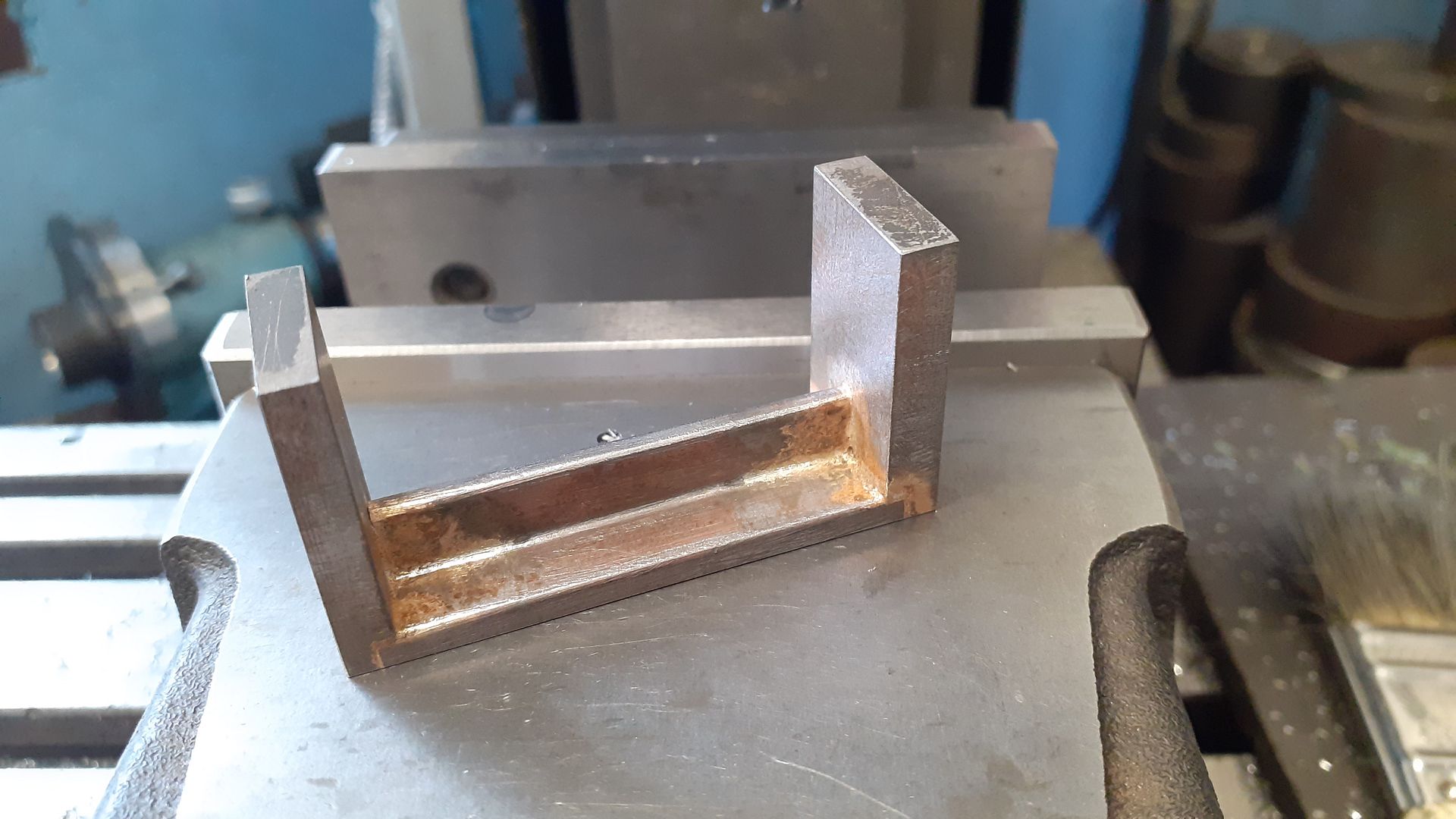
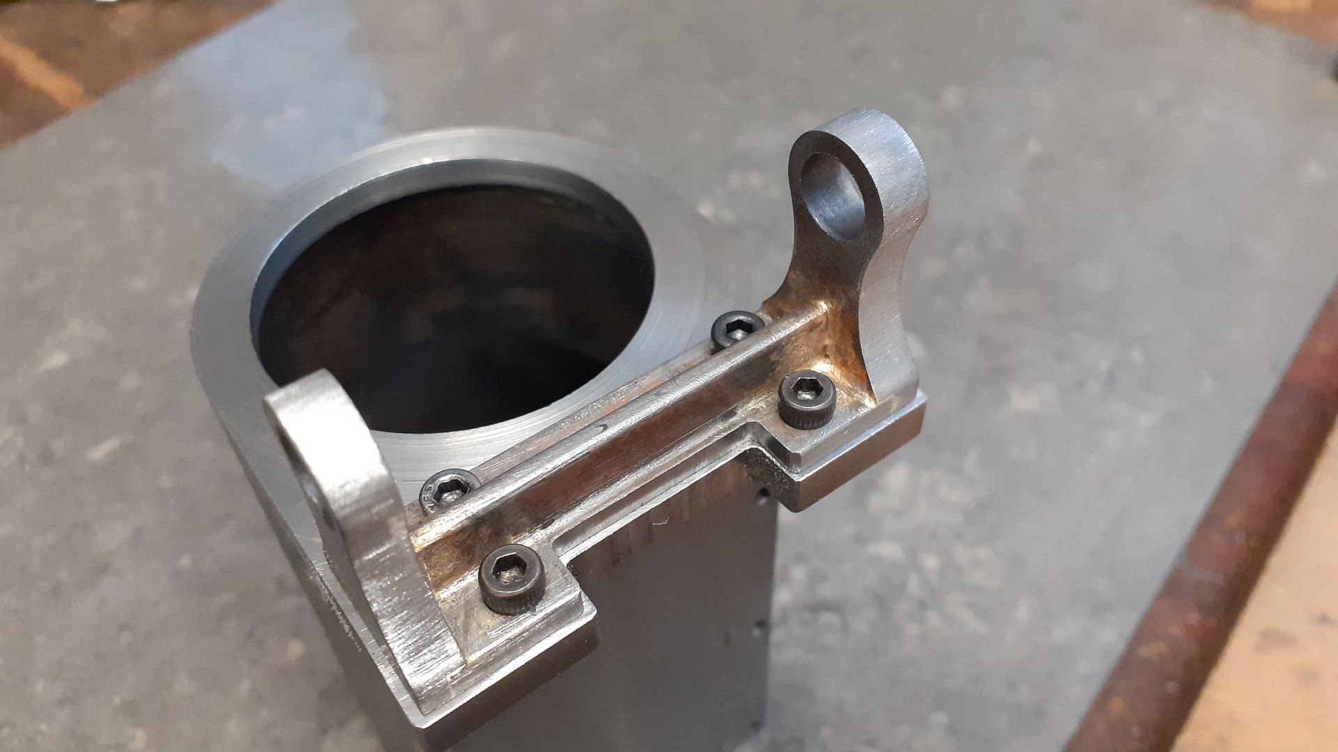
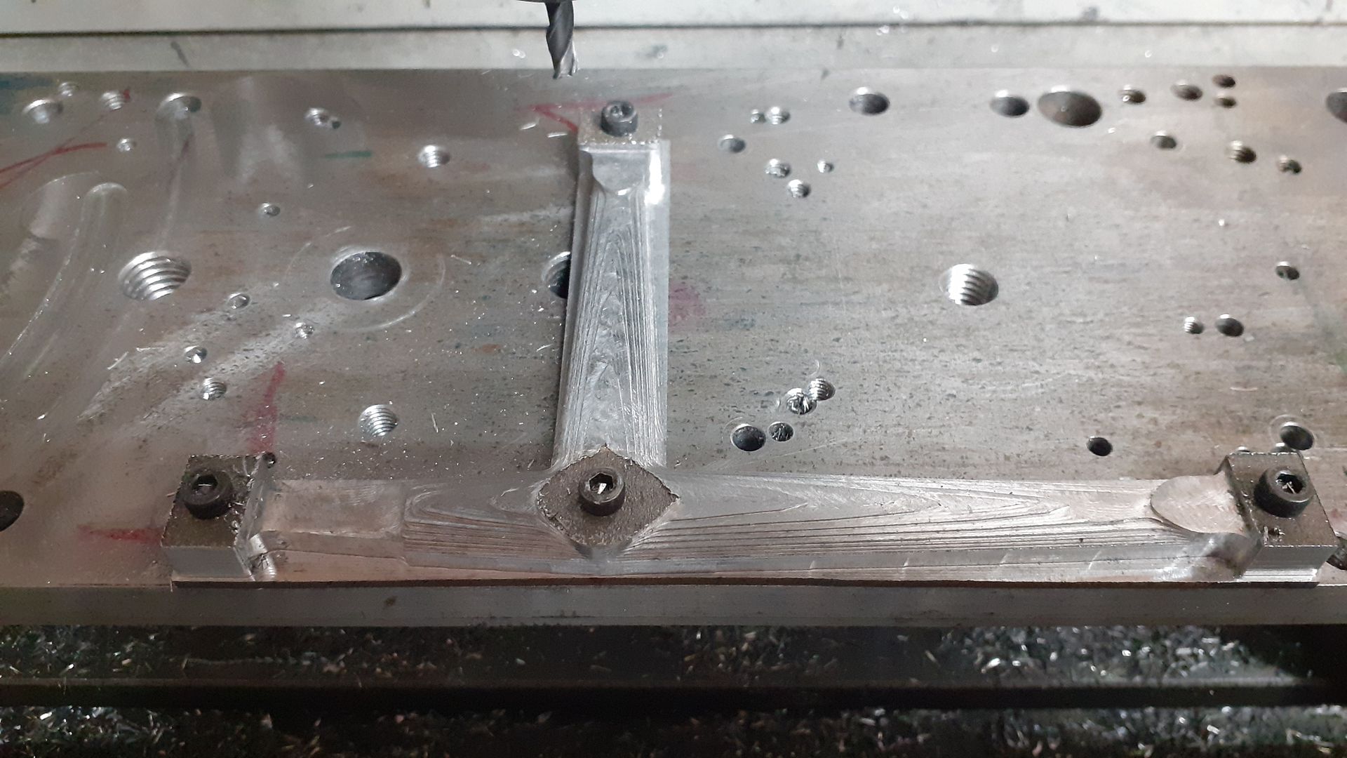
The bracket that the beam pivots on is a “u” shape which I fabricated by milling the inverted tee section and then silver soldering two end pieces to.
The holes for the bronze bearings could then be drilled and reamed, the vertical ends shaped and a notch milled out to clear the flywheel.
A quick trial assembly to see how it looks so far, next will be all those links and levers.
It’s getting close. I have about 140mm in the Y axis add to that 6mm for cutter diameter takes me to 146mm. If I do a similar flywheel where I don’t mill the outer face or outer edges then something like 160mm dia would be my limit.
Though I could do it in segments if I indexed the blank around so something like 300mm dia would be possible doing it that way.
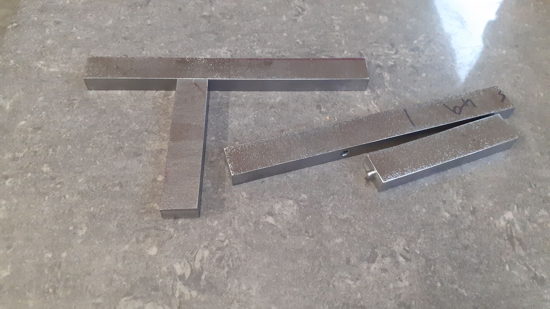
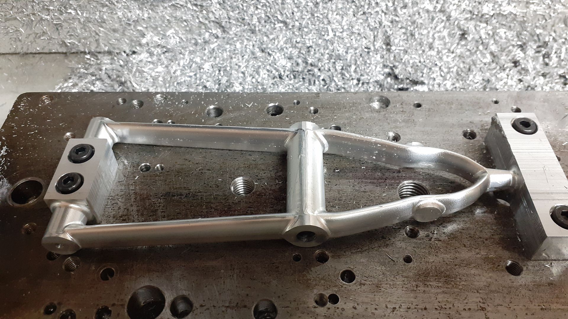
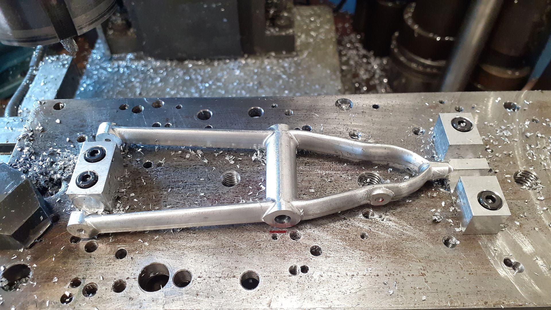
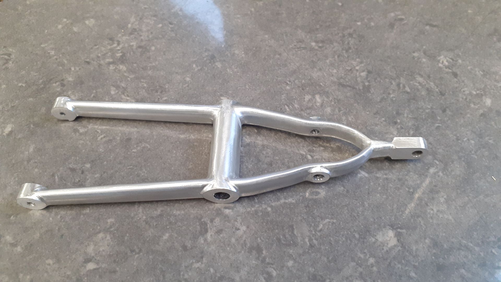
The two “T” shaped links either side of the engine are the most prominent so I decided to tackle them first. There would be a considerable waste if they were cut from solid as that would need to be 16mm thick due to the central pivot, even if I added material to the pivot so that I coudl cut it from 8mm thick plate the tee shape meant there was going to be a lot of waste. So I decided to fabricate the basic Tee and shape that then add some additional material to thicken up the boss.
The first job was to square up some strips cut from 180x 8 flat black bar and drill holes for locating dowels to keep the parts in position while they were silver soldered.
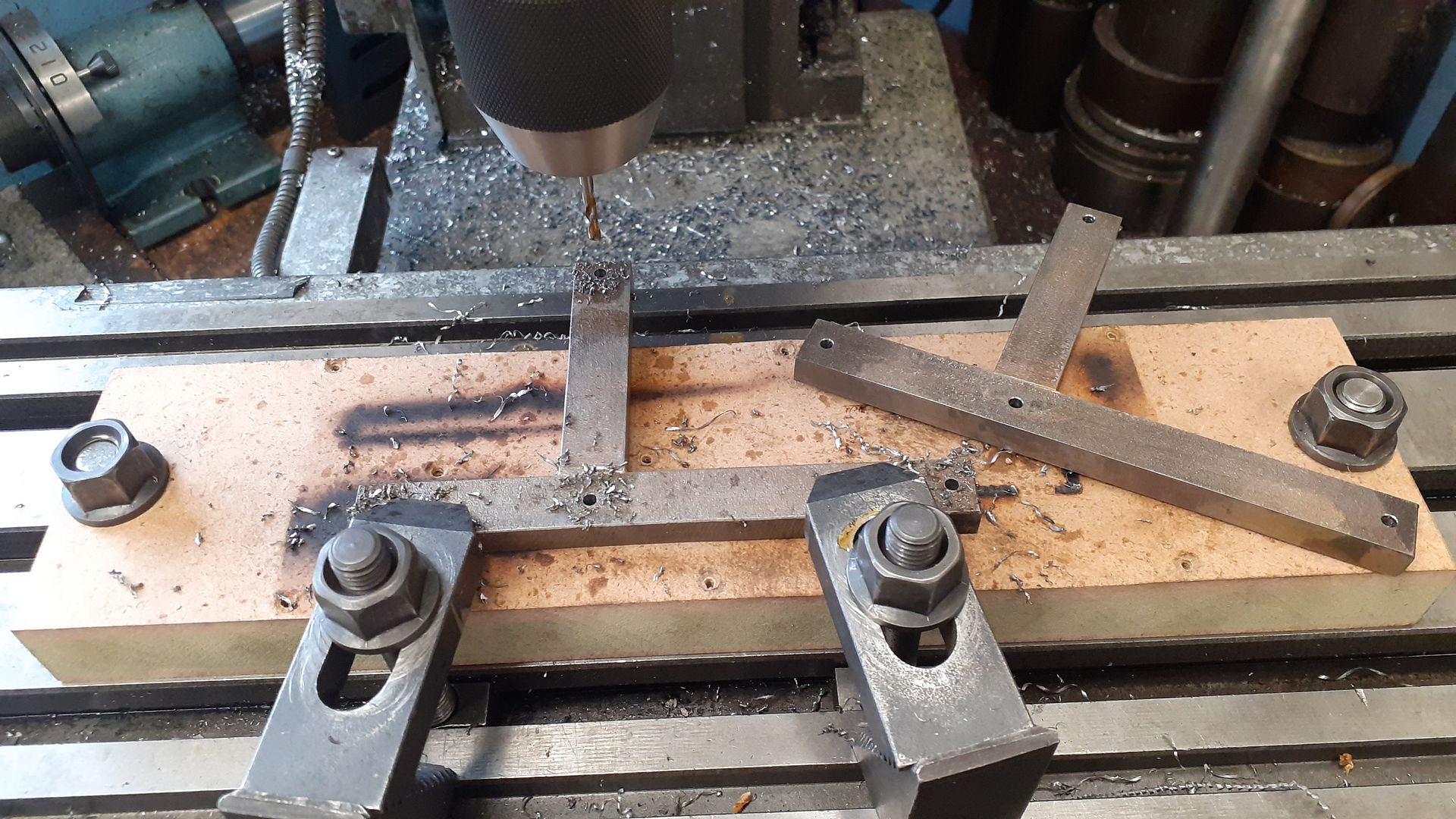
After a quick pickle I drilled some 3mm holes to use to hold the work down, only the one at the junction is going to be used , the others are in the waste material of the overlength pieces.
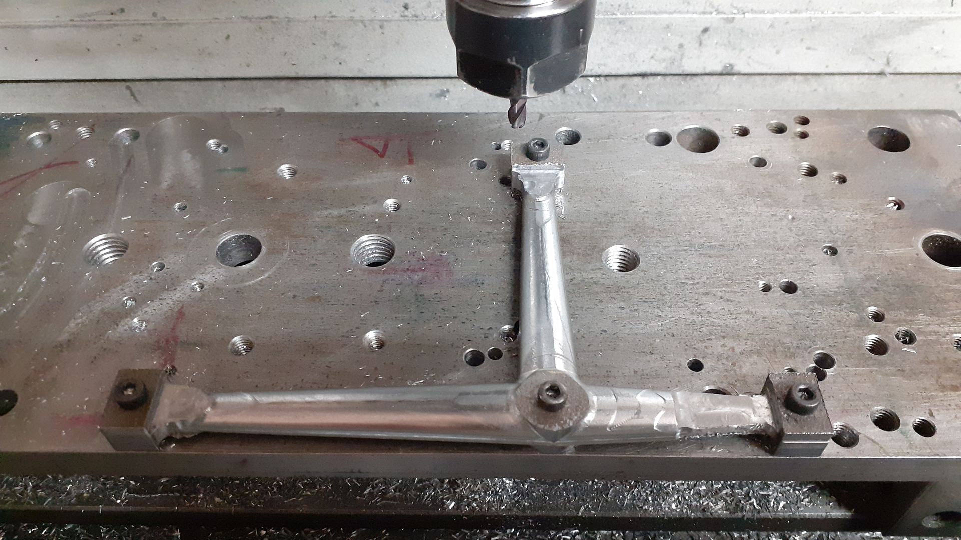
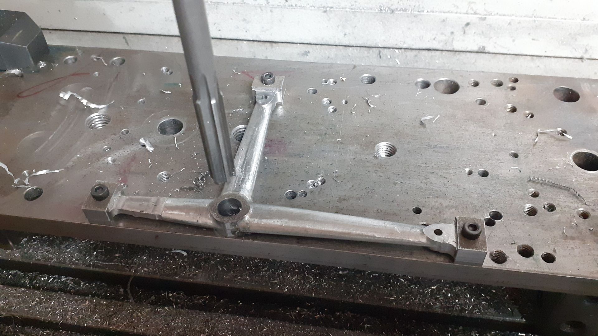
The much used machining plate was clamped to the table of the CNC and 4 matching holes drilled and tapped M3, actually I did 6 holes so the part could be flipped the other way round to machine the opposite side. This photo shows the arms screwed down and having had an adaptive cut to remove most of the waste material, leaving 0.3mm for the final cuts. 4mm 3-flute cutter used.
I then did a “scallop” finishing path with a 4mm ball ended cutter stepping over 0.2mm per pass which gives an almost paint ready surface, just a bit of needle file work due to a small amount of Z axis backlash where the cutter changes vertical direction.
After shaping both sides the smaller holes were drilled and tapped and the larger pivot hole reamed for a stepped extension piece.
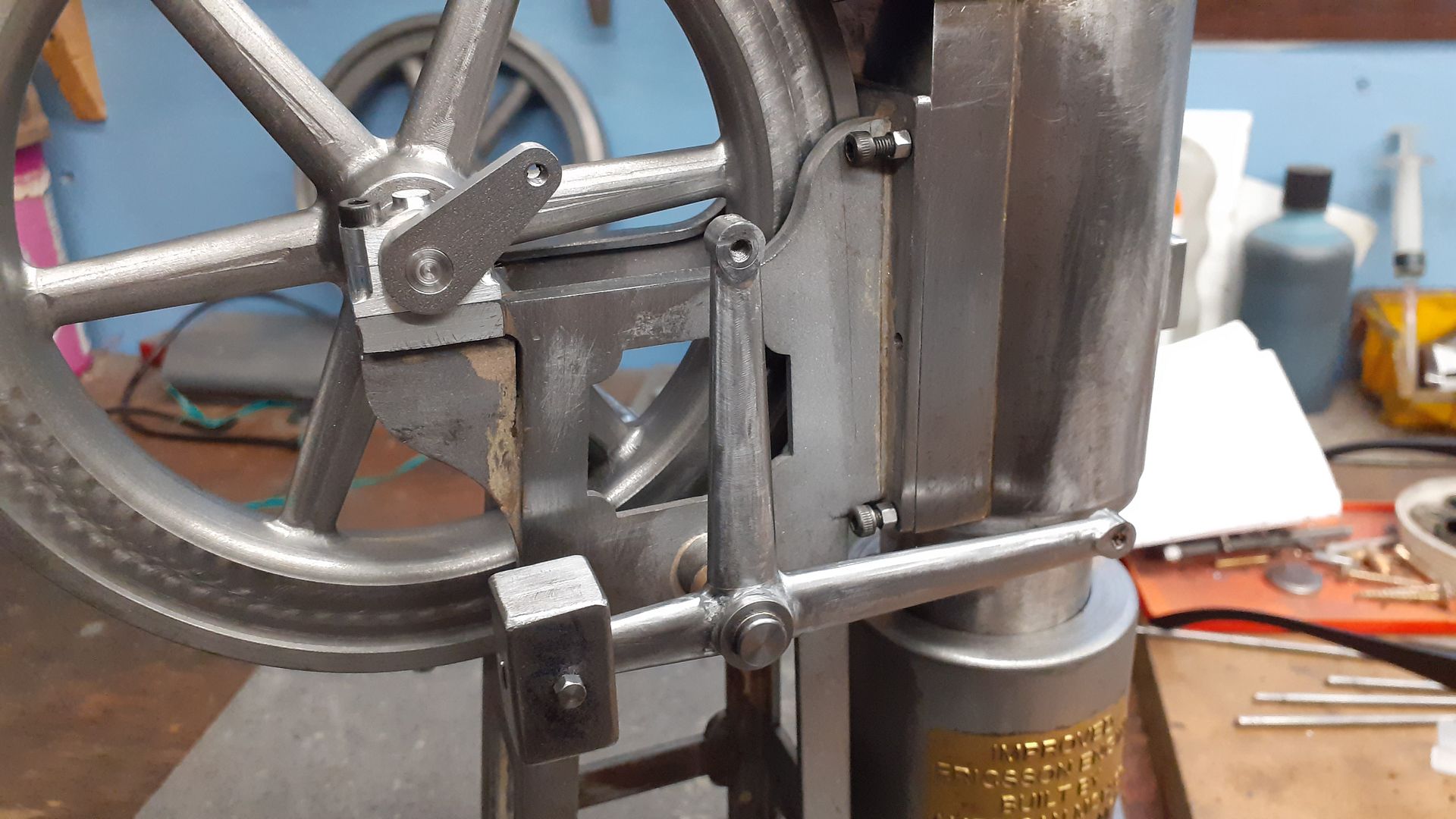
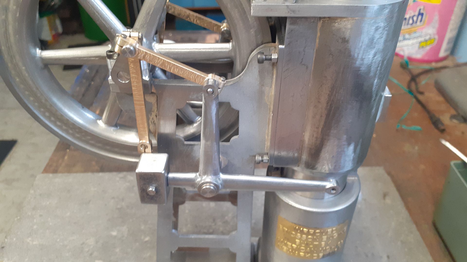
Here it is in place after JBWelding on the boss extensions and giving it a shoe shine with strips of emery. The counter balance weight was made from two halves so the tapered internal slot could be milled before soldering together and given a final cut to bring them it size.
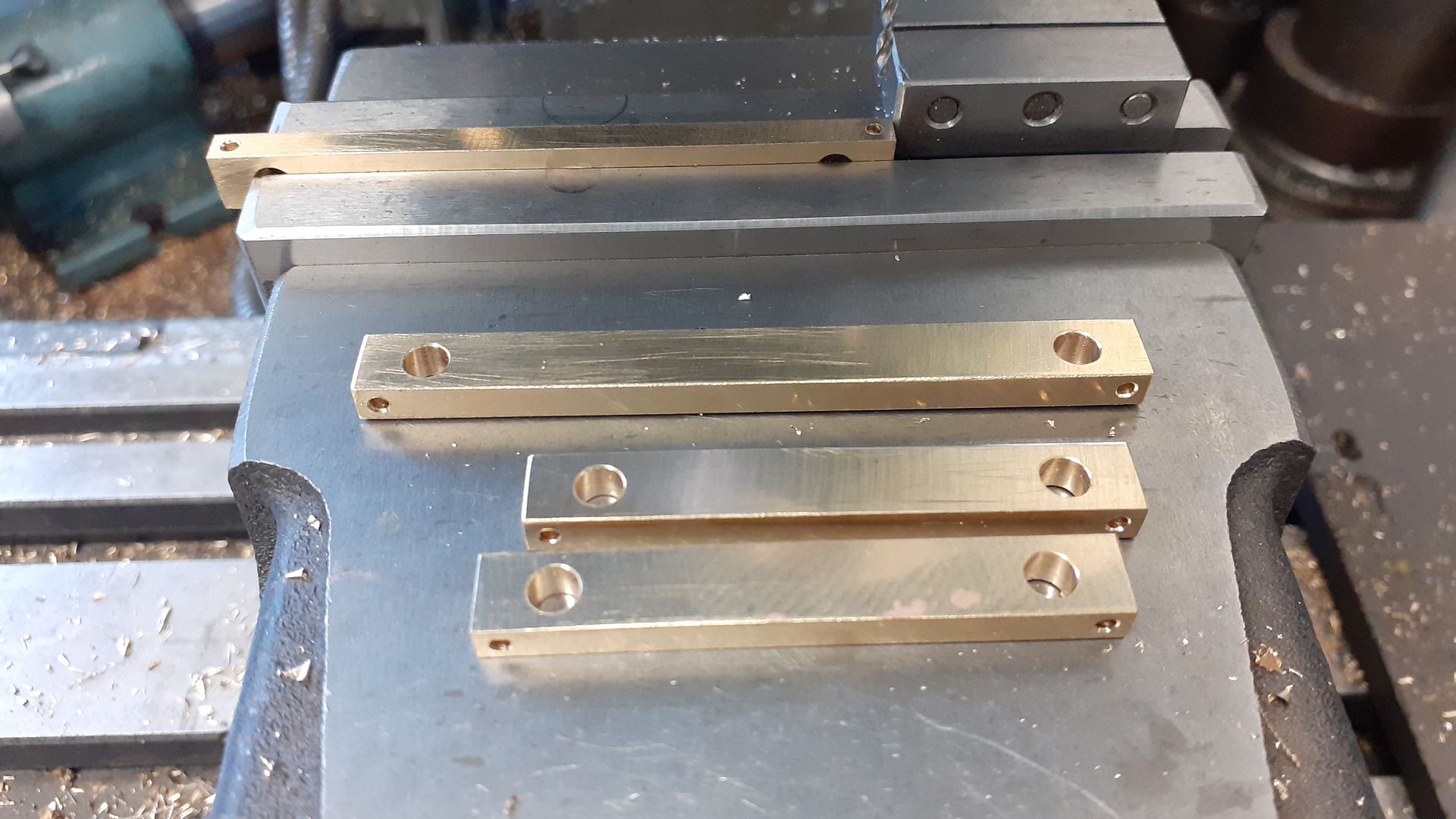
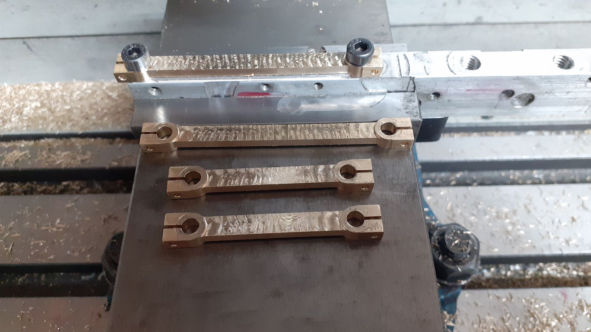
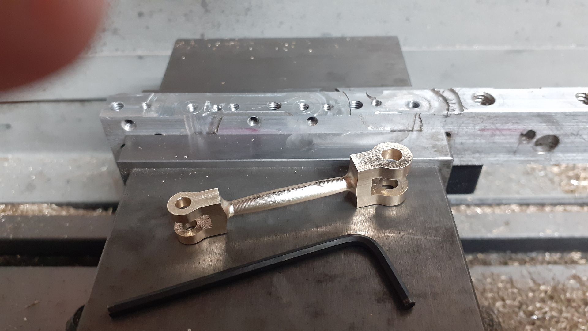
The links from crank to Tee and from Tee to beam are basically the same except for being a different length so were all done as a batch. First some brass was milled down to overall size then drilled, reamed and slots cut as required
These were then screwed to a waste block and the cuc used to reduce the central section in both width and thickness leaving the rounded and filleted junctions to the ends.
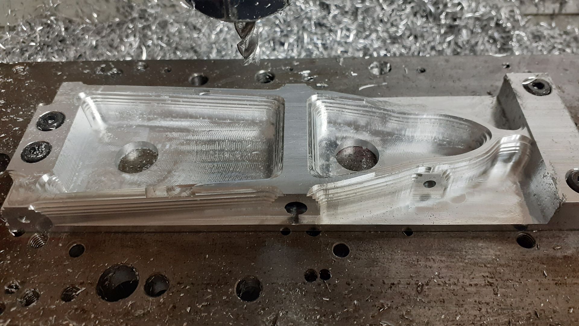
The next thing to be done was the beam that ties everything together. I started with some 2″ x 1/2″ aluminium flat bar and drilled & counterbored some mounting holes in it so it could be held to a machining plate. I also drilled in from the sides for some of the pivot pins while it was a nice easy shape to hold. With it then bolted down to the CNC’s table I removed the majority of the waste from one side with an adaptive tool path, this leaves quite noticeable steps much like the contour lines on a map except these were ar 1mm height increments.
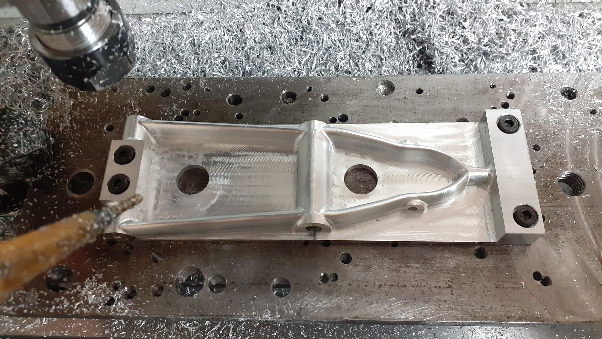
Changing to a 4mm diameter ball nose 4-flute cutter a “scallop” tool path was used to refine the shape, the tool stepping over 0.2mm per pass leaves very little handwork to complete.
The material was then turned over and two similar paths used to machine the opposite side.
Back to the manual mill and with a 6mm cutter the material that had been used to hold the part was separated leaving just 0.25mm thickness at the bottom of the cuts which could be cut through and the surface cleaned up with a file.
A bit of rounding over of the right hand end and that was another part crossed off the list.
The last shapely link required was the one from the end of the beam to the top of the pump rod. I milled a piece of brass to size, reamed two holes and slotted the ends manually before using a similar process to the beam to shape the ends and fish bellied central section.
Thanks, all the bits could be carved out manually but the CNC does help to simplify things once you have learnt how to use it and come up with teh CAD in the first place.
The piston started life as some 45mm continuous cast bar, I turned the OD to fit the previously machined liner and cut a groove where the piston packing goes leaving material beyond that to form the upper link lugs from. Like the Heinrici rather than trying to hollow out the piston from above I removed most of the material from below and created a shallow recess that a disc of cast iron could be pressed into to form the bottom of the piston.
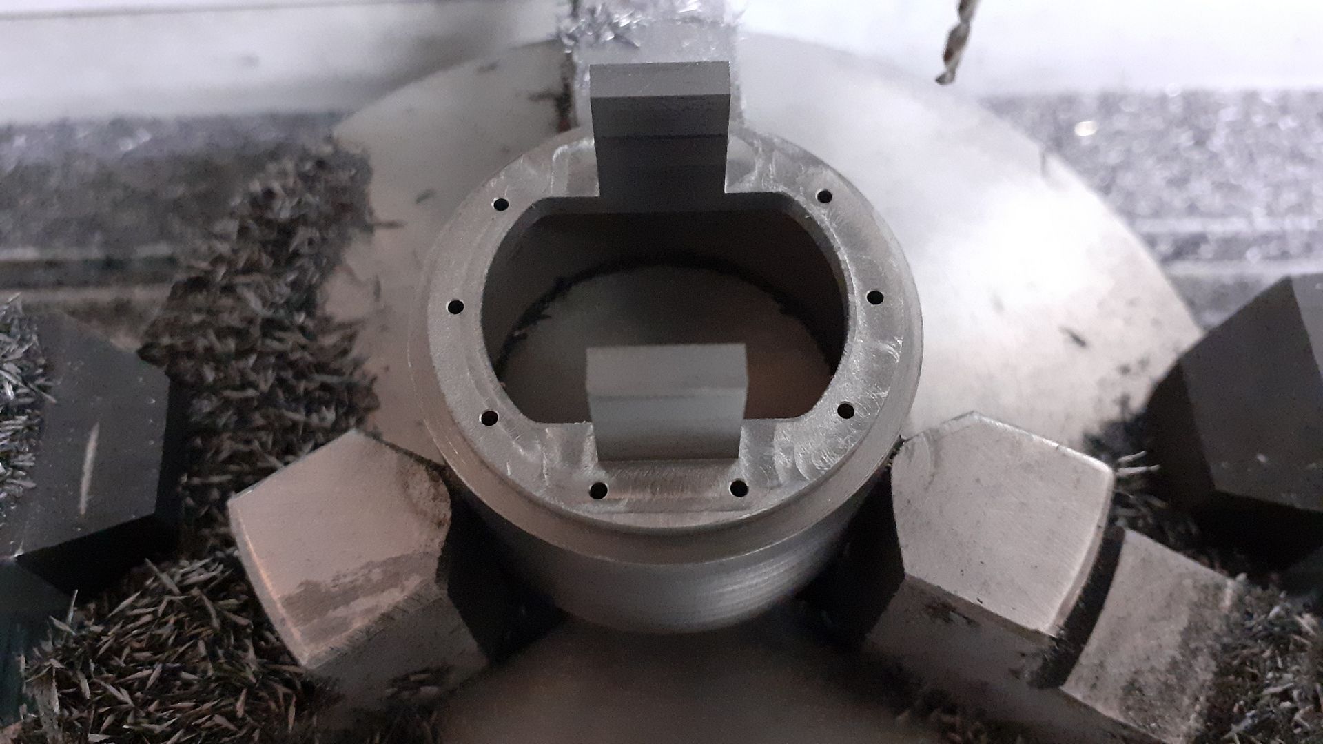
The CNC was then taken advantage of to machine the top flange of the piston with its two flats and leave the lugs standing proud. I also did the eight holes that are used to hold the packing retaining right at the same time though they were tapped by hand. After this photo the lugs were drilled and tapped for pivot pins and then the ends rounded over.
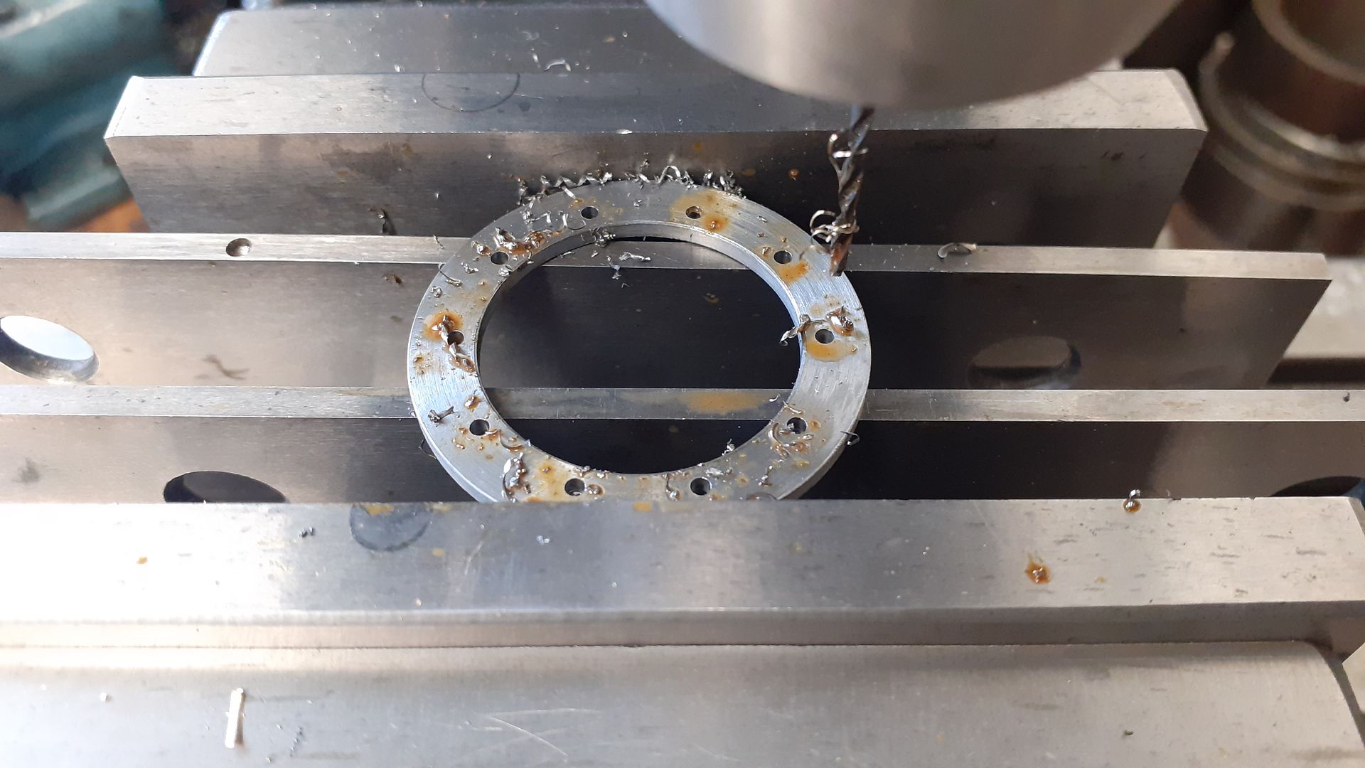
The packing retaining ring is just a simple turned steel “washer” with some holes. I’m not sure whether I will bother with any form of piston ring/packing as if the piston fit is good I’d rather have the lower friction and just run iron on iron. I will decide after test running.
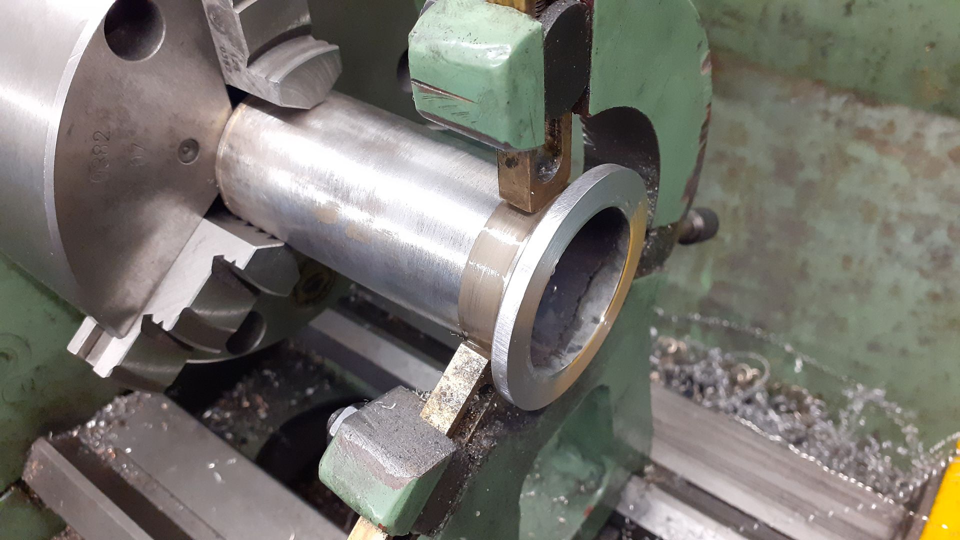
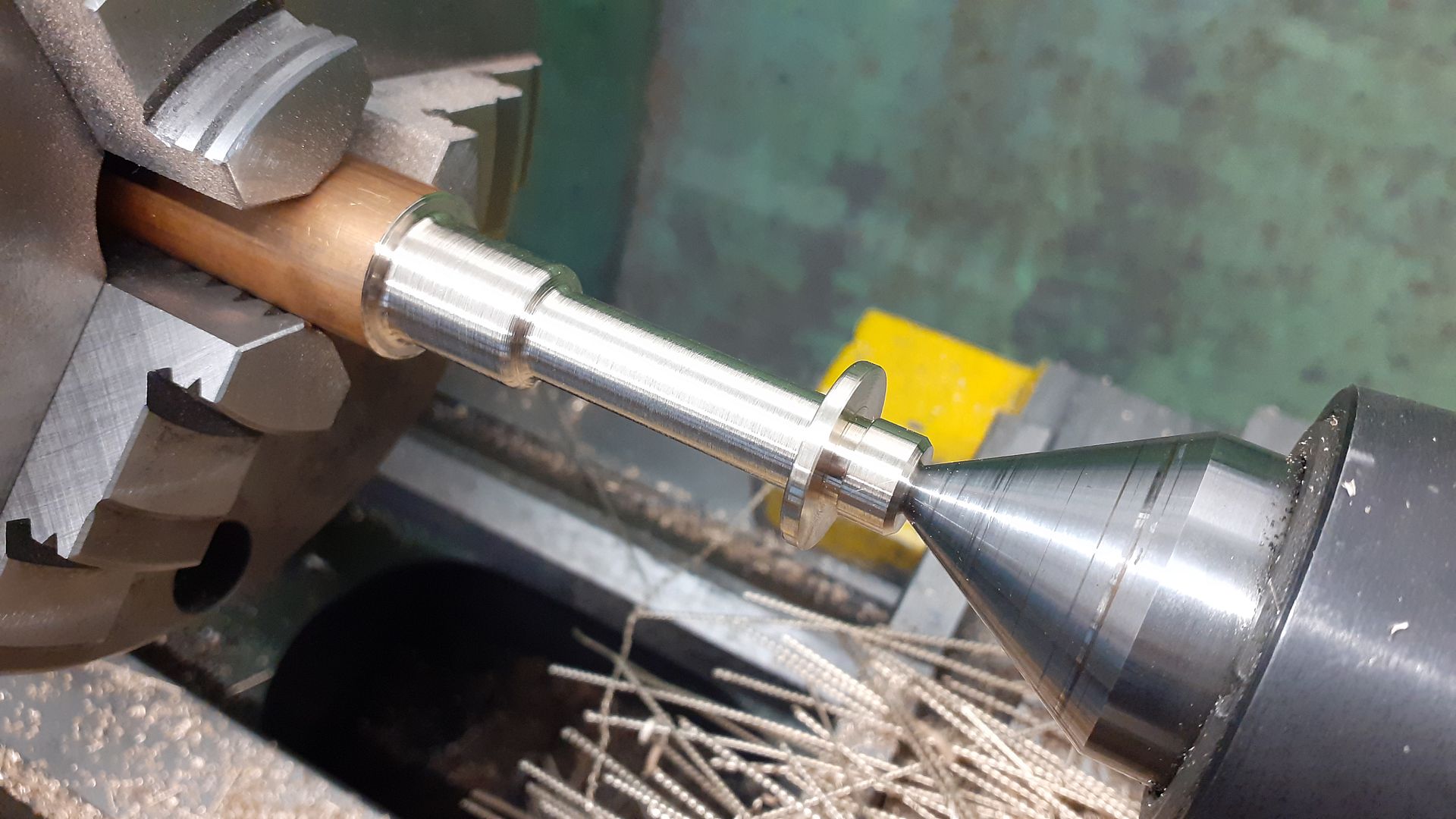
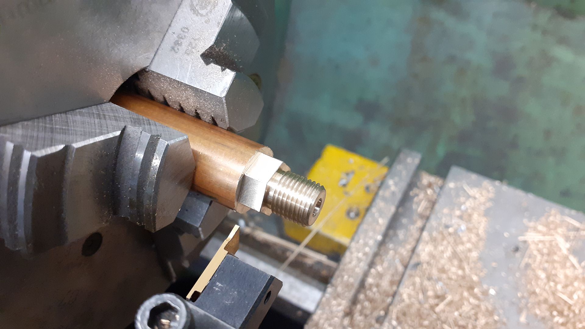
As the displacer rod has to pass through the power piston it needs a sleeve and gland, this is the sleeve being turned, the diameter closest to the tailstock ctr will have a fine thread cut onto it which will hold the sleeve’s flange against the bottom of the piston with a lock nut the other end will be opened out and threaded for the gland nut. There is a 4mm dia reamed hole through the whole length. Again may not need any gland packing.
The gland nut is straightforward turning, threading drilling, reaming then mill the hex before parting off.
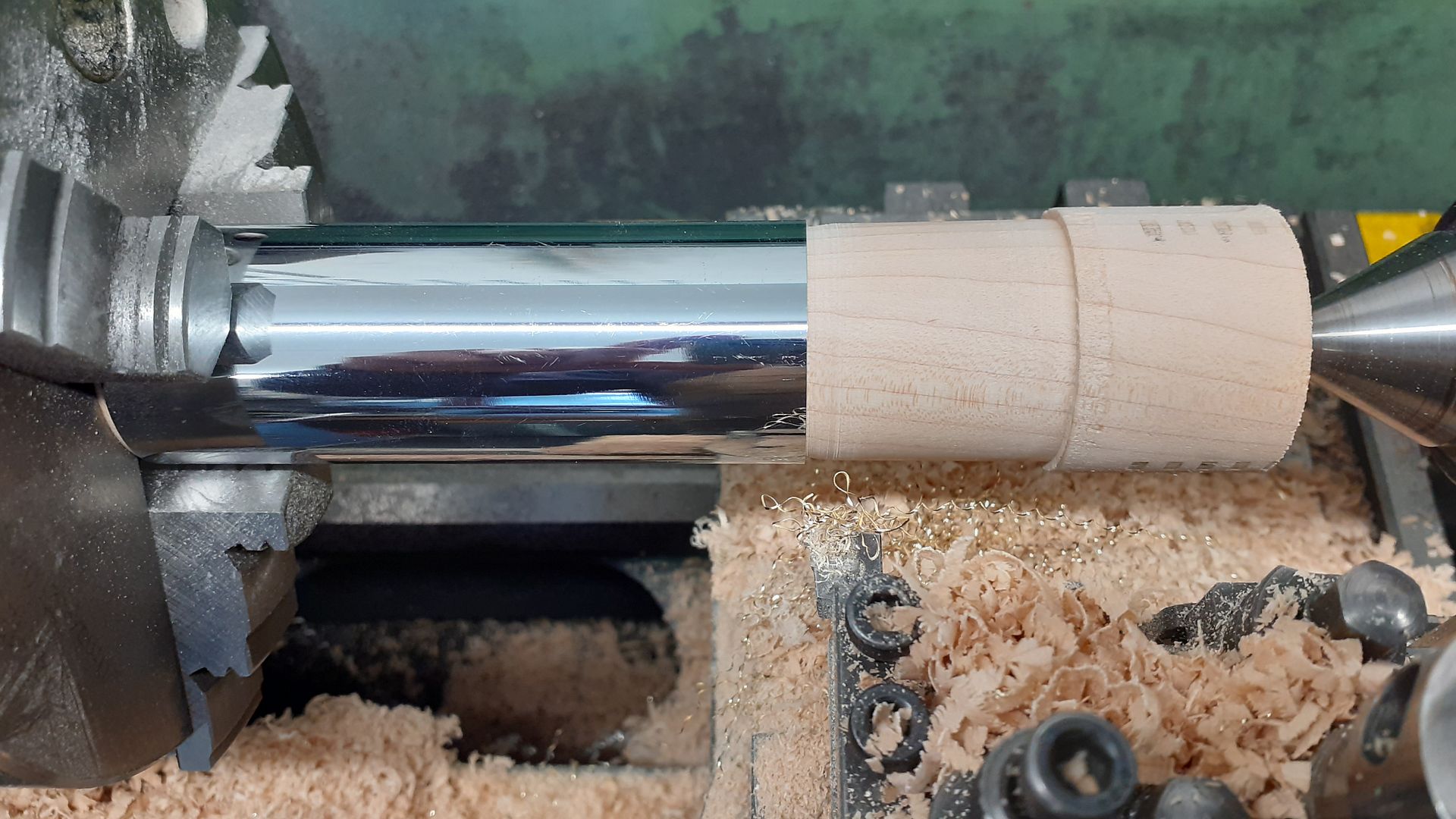
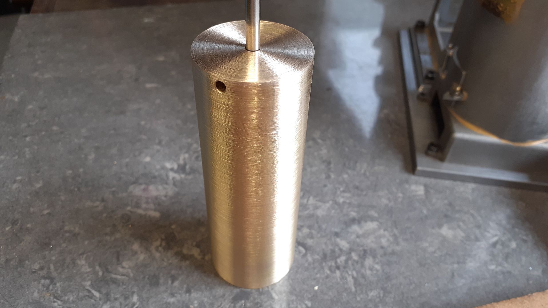
The displacer started out as some brass waste pipe, something like 0.35mm wall (0.015″) so I turned a scrap of maple to a tight fit and used that to support the tube while I held it in the 3-jaw to square off the ends. I also held it like this to Emery Coth the chrome off.
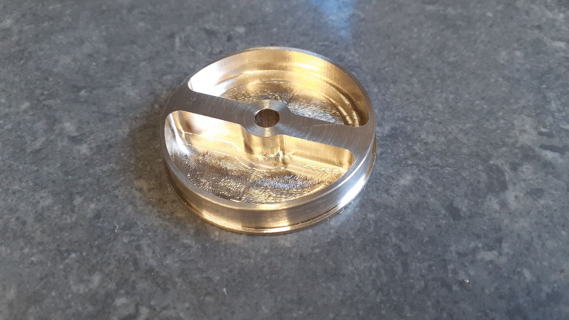
The bottom was just a piece of 1mm brass Sif Brazed in place but the top needed to be thicker to accommodate two grub screws so it’s position on the rod could be adjusted. To keep the weight down I hollowed out most of this part just leaving two ribs where the grub screws would go.
After silver soldering the top on it was given a clean up and the two holes for the grub screws drilled and tapped
The yoke that lifts the displacer via two smaller rods that come up from the Tee shaped arms was turned and then held in the indexer to mill the ends to rectangular section and add some holes. After that the ends were rounded over and slotted so the outer bolts can be used to clamp the yoke to the rods.
The build of this engine is going to take a short break. I originally made a start on it while waiting for the RLE flywheels to arrive which they eventually did so have dropped back onto that.
Also in the same delivery as the RLE flywheels were a few more castings and a couple of pre machined parts complete with special brown coating. Graham orry had sent me these after a comment I made in another thread so not being one to turn down a challenge I have designed an engine to make use of these items so won’t get back to the Denny until that is done (won’t be long now).
But I will leave you with this. I had enough parts made for a test run so thought why not give it a go. First I tried with a couple of blow torches aimed into the furnace hatch but that did not really work. I then removed the furnace and put a camping stove burner under her and away she went at a fair lick. Towards the end of the video you can see I have drilled a hole in the base so the burner can be placed lower down and replaced the furnace, this has slowed things down and I think blocking some of the burner holes will slow it even more. At this stage there is no water pump connected so I am just running compressed air through the jacket to keep a reasonable temperature. There are also no gaskets, piston ring or gland packing, just machined fits and in the case of the piston/cylinder some lapping.
After the distractions of a couple of other engines I got back to this one to do the last part which was the water pump. Not only is pumping water the main use for these engines but the water also serves to pump the cooling water around the cylinder before exiting to it’s final destination.
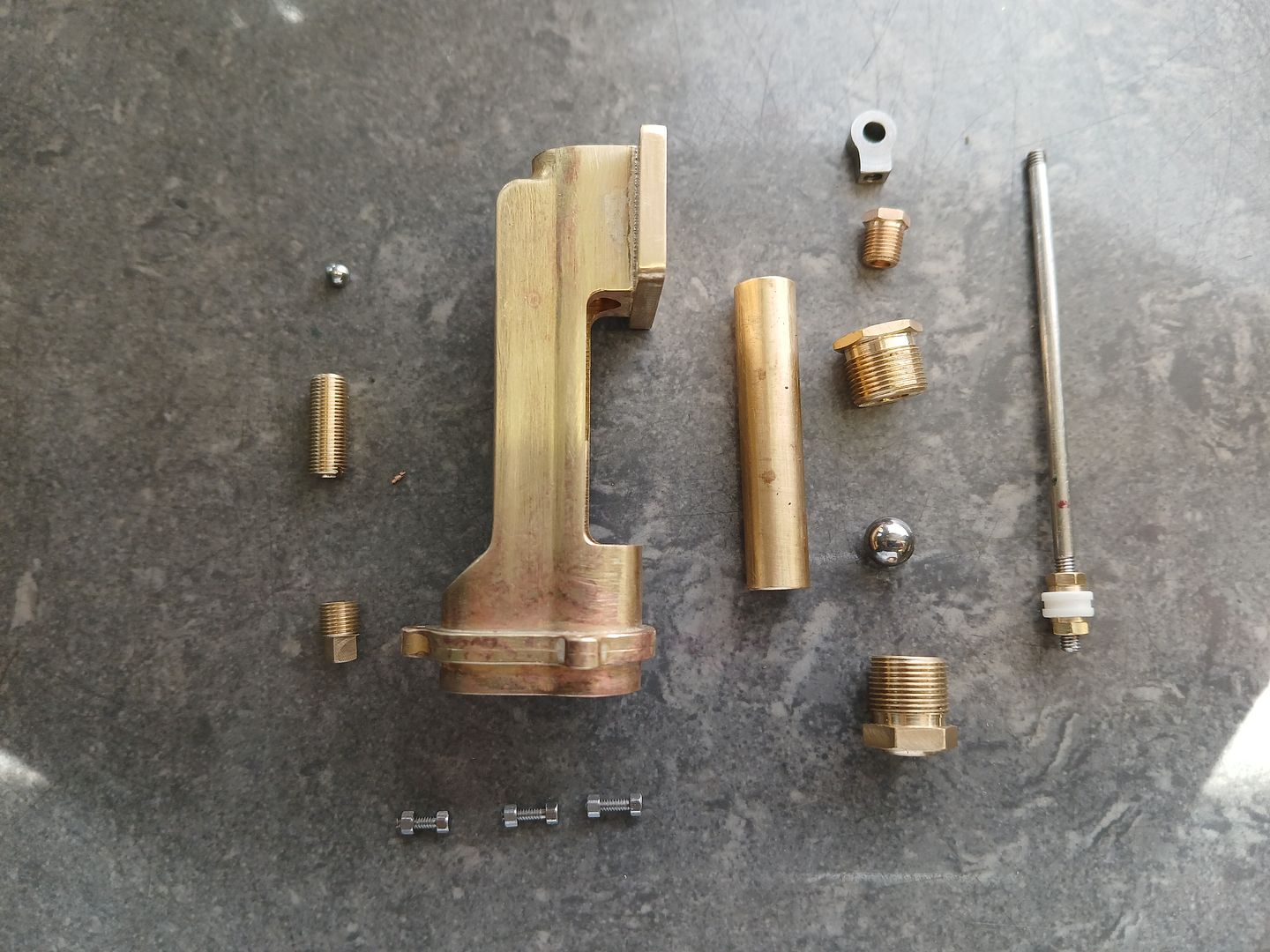
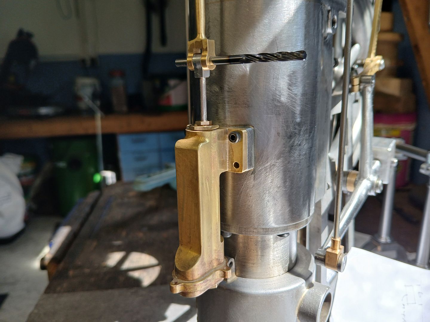
Looking at photos of full size and the Patent the 1/4 scale drawings were not quite right externally so I drew mine to hopefully be a bit closer to the original, the most noticeable feature that I added was the flange where the bottom of the pump mounts to the main body though mine is a dummy.
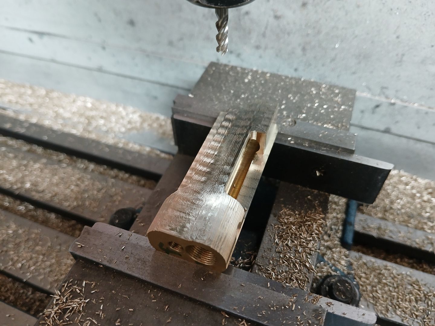
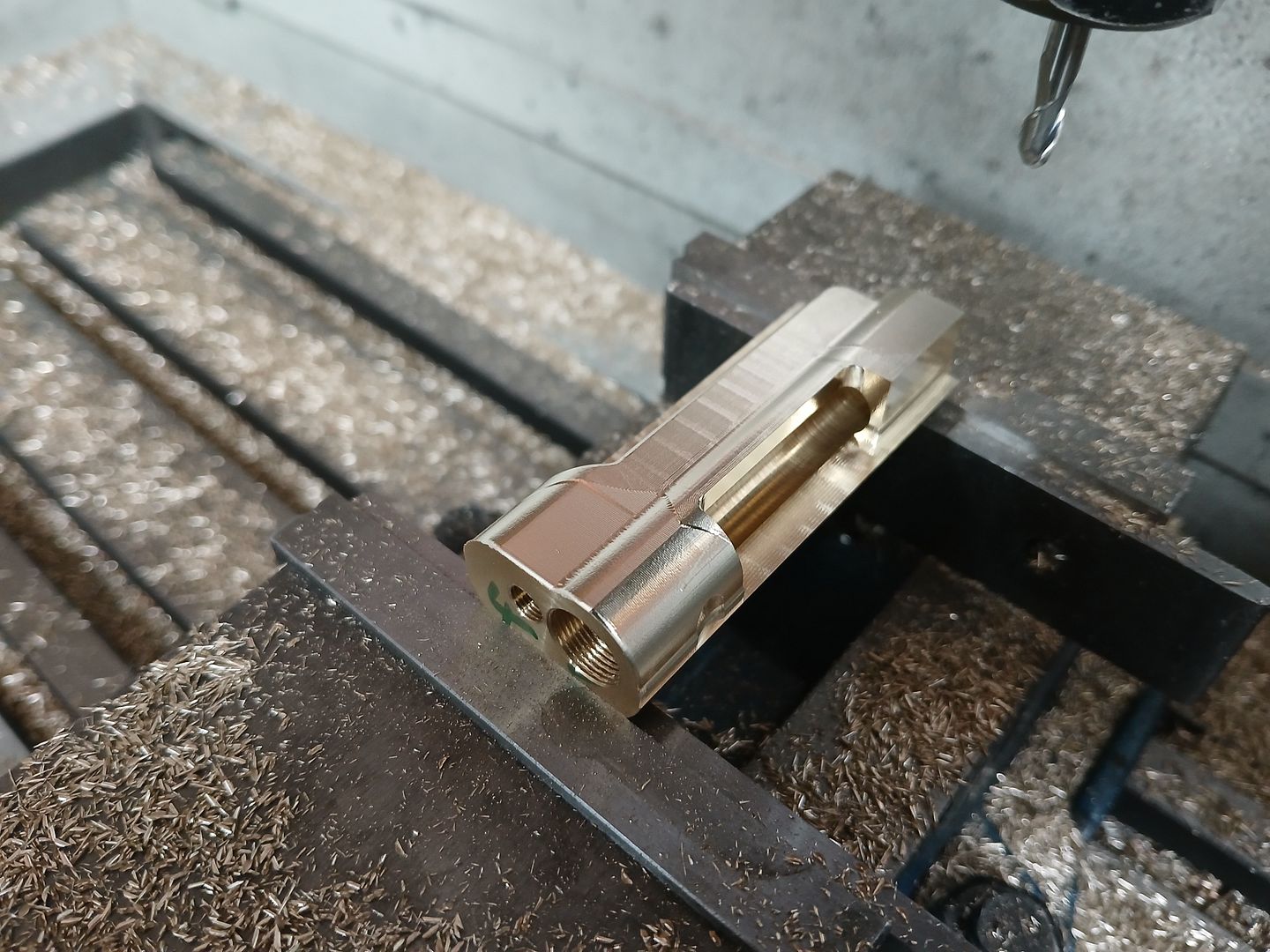
I started by facing and then milling two flats along the length of some 1″ brass bar so that I had some ref faces to work with and then drilled, reamed and tapped the long holes using the 4-jaw. Then over to the CNC firstly with an adaptive path to rough out from one side.
Then a couple of finishing paths though the majority was done with a scallop using a 3mm dia ball nose cutter stepping over 0.2mm per pass. After that it was flipped over and the other side cut.
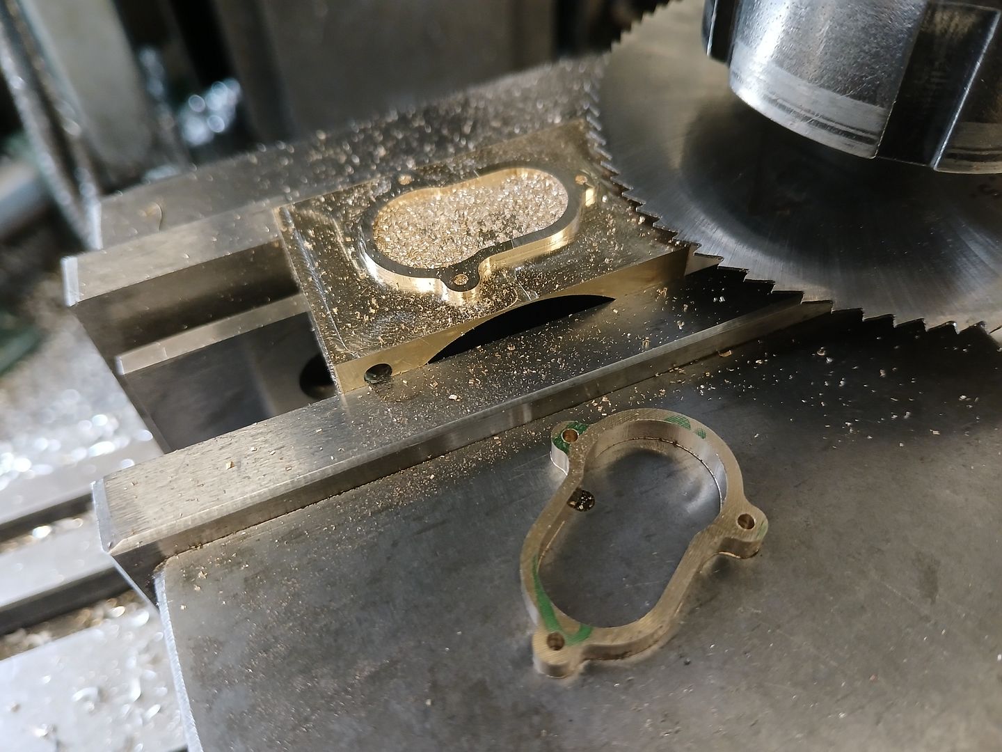
The bottom flange was also machined on the CNC before being “parted off” with a slitting saw
The flange and a piece of flat material were then silver soldered to the body, the flat material milled to final size and thickness then drilled along with a few other cross passages. The remaining parts were just turning and a bit of milling to form the hexagons.
All seems to move as it should once assembled, just got to make the pivot pin to replace the 3mm machine reamer I am using in the photo.
I’m undecided about how much plumbing I will do. I generally run my engines for short periods and therefore don’t put water in the hoppers so will not really need any water circulating and there is little point in making and fitting dampers when the engine is not pumping to any head or against the restriction of long pipe runs so may just go with a couple of short stubs of pipe. If that is the case then all is ready to start painting.
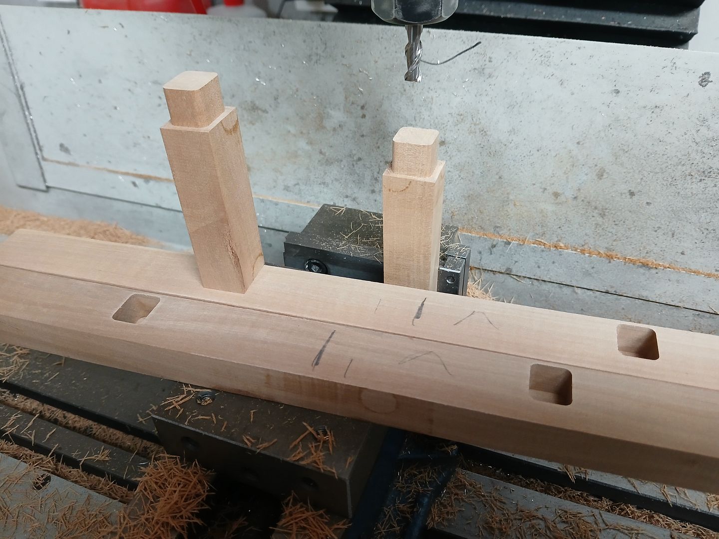
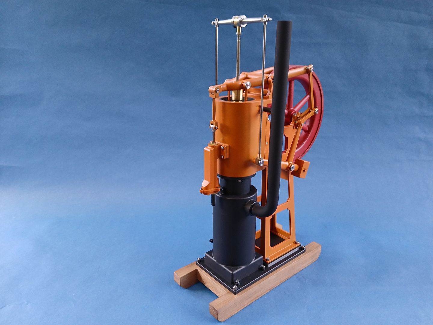
The last thing to make was a wooden sled to mount the engine on as it needed to be raised up to clear the camping gas burner body. The CNC makes quite a neat job of mortice and tenon joints
Then a coat of paint, the bed plate and furnace were done in a stove paint, the pumpkin orange and dull red flywheel are close to original colours and I gave then a coat of clear matt as it did not want the orange to look too flashy.
It’s knocking a bit as I removed the pump’s piston so I could blow air into it for cooling so the rod is not being guided that smoothly but otherwise not running too badly.
Terrific thread to read on its build Jason, takes a big effort to do all those photos (bloody excellent machining) and what a superb engine you ended up with! – Cheers Jim
Yes, looks good – I find it quite hard to pick up the ‘mental thread’ of where I left off with builds that get interrupted – Do you keep organised notes & files for all your ‘jobs’, you often seem to have a number going on at any one time..?
No I’m not that organised, just try to keep my 3D CAD upto date with anything that gets changed during construction so that if I come back to it the sizes for the next part will be right.
Lube is just a small amount of clock oil which is very thin and light so minimal drag. There is supposed to be a piston seal (ring) but it seems to run well enough without so I have not got that fitted at the moment, just iron piston on iron liner.
Author
Posts
Viewing 25 posts - 1 through 25 (of 25 total)
Please log in to reply to this topic. Registering is free and easy using the links on the menu at the top of this page.