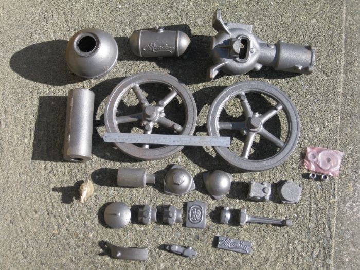
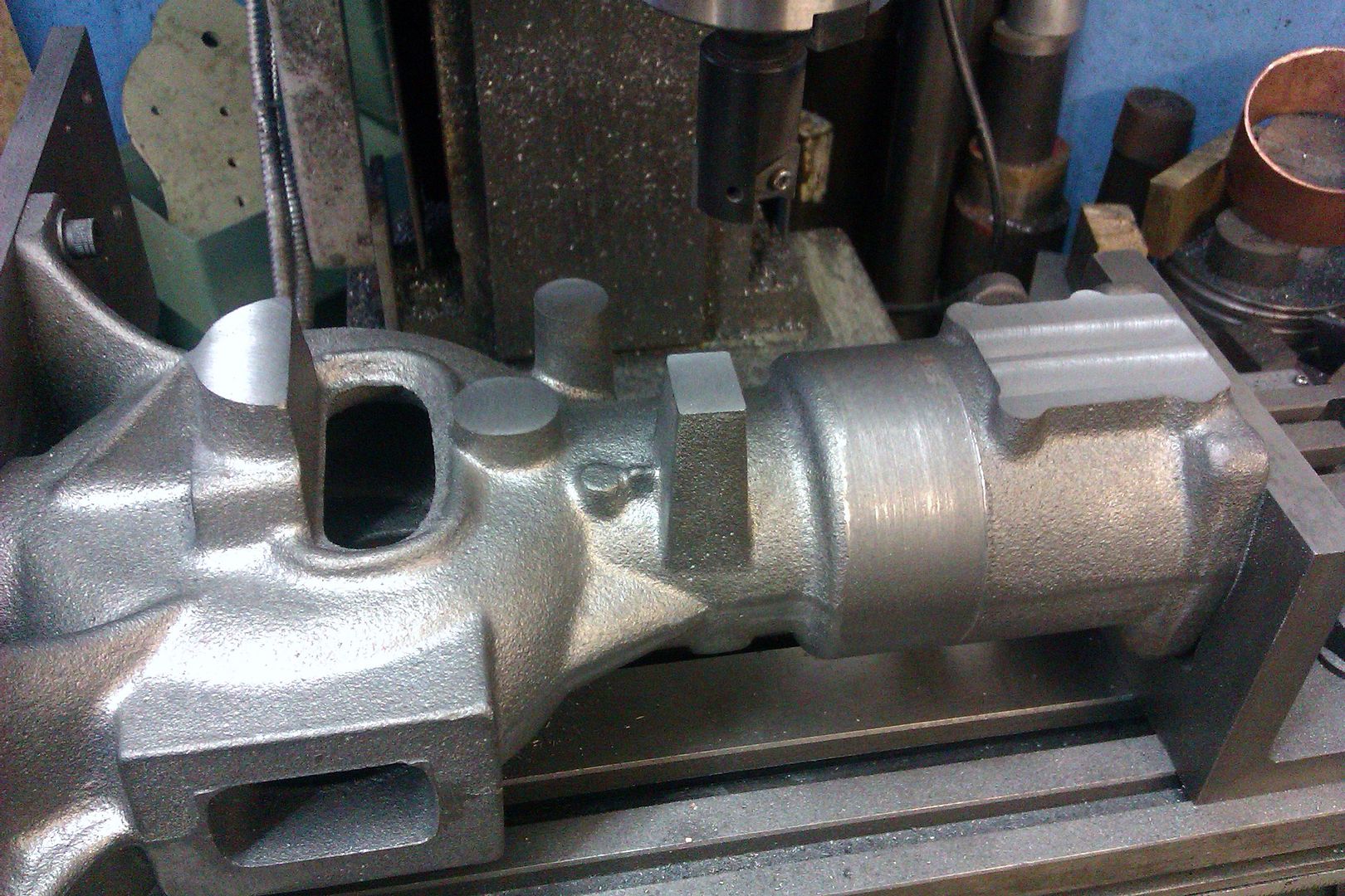
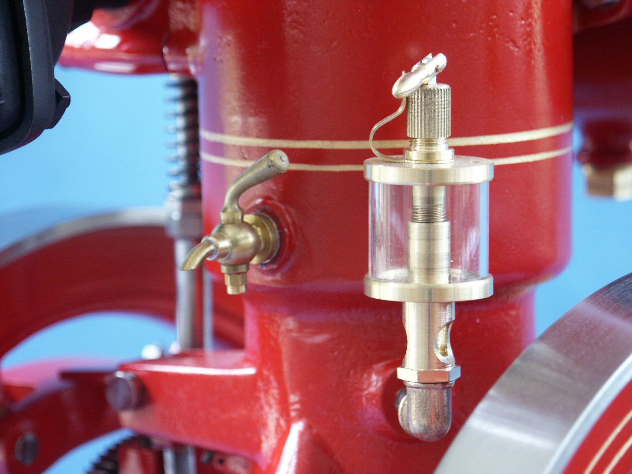
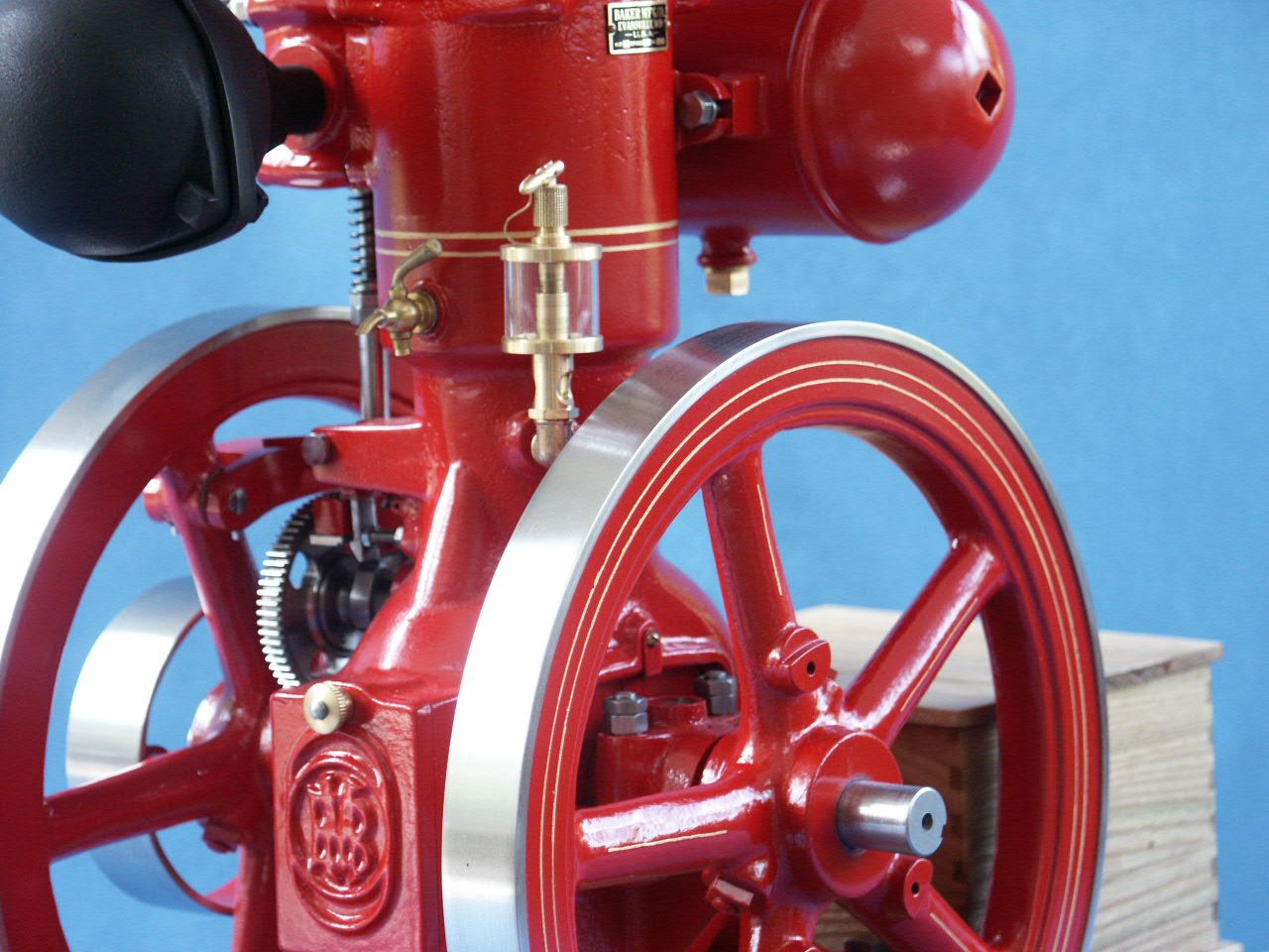
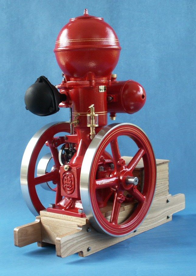
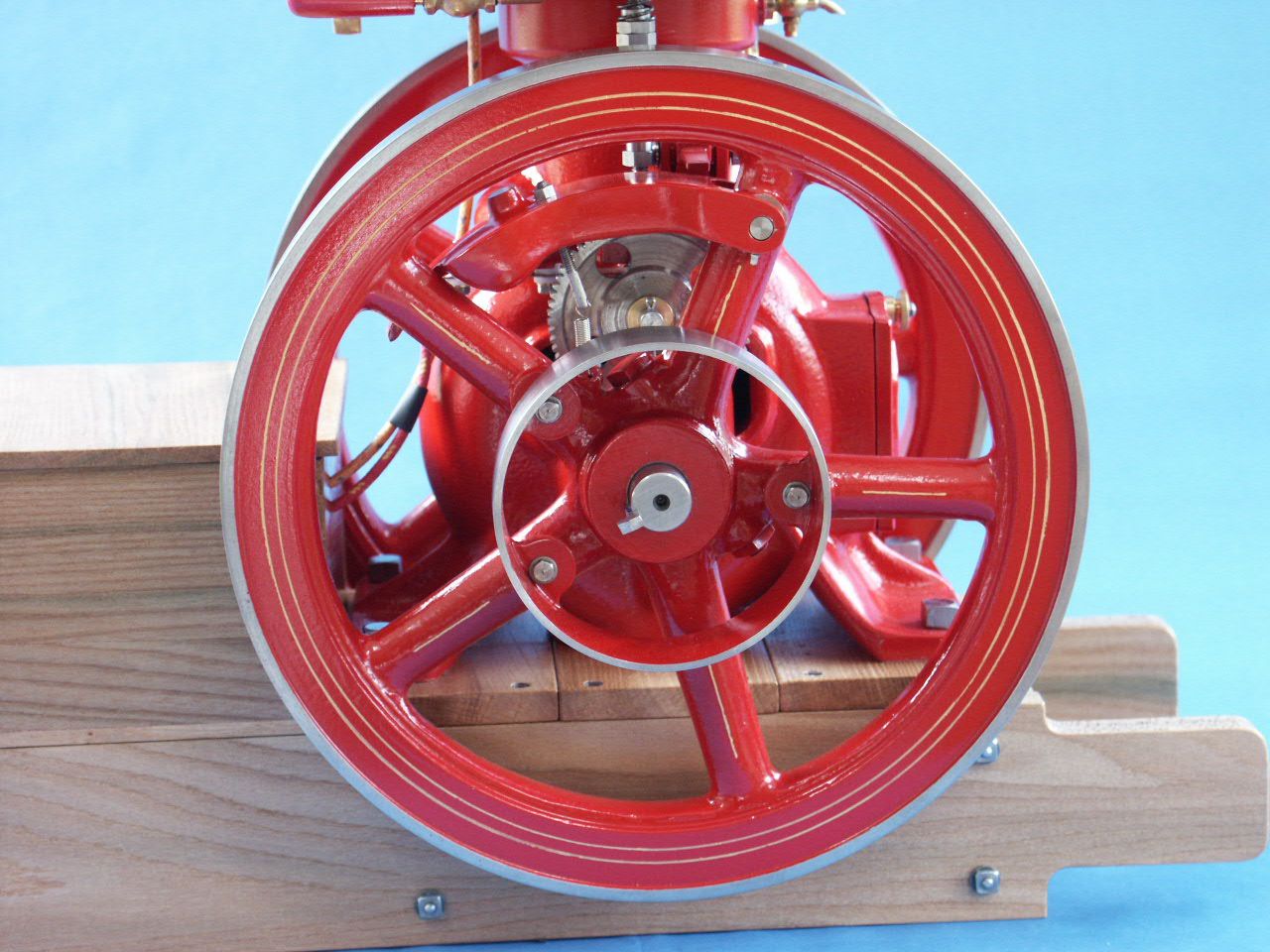
1/3rd Scale “Ball Hopper” Monitor Build
1/3rd Scale “Ball Hopper” Monitor Build
- This topic has 26 replies, 7 voices, and was last updated 19 September 2023 at 11:03 by
 JasonB.


 ]
]


- Please log in to reply to this topic. Registering is free and easy using the links on the menu at the top of this page.
Latest Replies
-
- Topic
- Voices
- Last Post
-
-
QCTP
Started by:
James A
in: Workshop Tools and Tooling
- 2
-
12 July 2026 at 14:27
MichaelR
-
Small electromagnetic pump via E-Bay
Started by:
Clive Foster
in: Manual machine tools
- 1
-
12 July 2026 at 14:00
Clive Foster
-
Myford VMC Spindle Advice Please.
1
2
Started by:
Nigel Graham 2
in: Manual machine tools
- 10
-
12 July 2026 at 13:54
Michael Gilligan
-
Boiler problem
Started by:
Zan
in: Help and Assistance! (Offered or Wanted)
- 5
-
12 July 2026 at 13:52
duncan webster 1
-
pitman arm
Started by:
martin haysom
in: General Questions
- 5
-
12 July 2026 at 13:22
noel shelley
-
Cleaning years of nicotine exposure and some touch ups
Started by:
rumz
in: Traction engines
- 2
-
12 July 2026 at 13:17
Dalboy
-
Smart & Brown model A spindle lock
Started by:
old mart
in: Workshop Tools and Tooling
- 2
-
12 July 2026 at 12:40
Steve101
-
1930 Austin 12 with 3rd brush dynamo
Started by:
john fletcher 1
in: General Questions
- 15
-
12 July 2026 at 12:00
Howard Lewis
-
Lathe coolant applicators
1
2
Started by:
lucerne
in: Manual machine tools
- 16
-
12 July 2026 at 11:41
Charles Lamont
-
First Printer
Started by:
vintagengineer
in: 3D Printers and 3D Printing
- 6
-
12 July 2026 at 10:51
Russell Eberhardt
-
Metal saw
Started by:
Speedy Builder5
in: Workshop Techniques
- 4
-
12 July 2026 at 10:25
martin haysom
-
Mini-lathe parts source
Started by:
Dunc
in: General Questions
- 7
-
12 July 2026 at 10:11
John Hinkley
-
SmallRig Cheese Plate
Started by:
Michael Gilligan
in: Workshop Tools and Tooling
- 4
-
12 July 2026 at 10:05
Michael Gilligan
-
Bridgeport Series 1 CNC
1
2
3
Started by:
tomcnc
in: CNC machines, Home builds, Conversions, ELS, automation, software, etc tools
- 12
-
12 July 2026 at 08:11
seemack
-
What Did You Do Today 2026
1
2
…
5
6
Started by:
JasonB
in: The Tea Room
- 41
-
12 July 2026 at 01:00
Nigel Graham 2
-
Another what’s this thread….
Started by:
Hollowpoint
in: General Questions
- 6
-
11 July 2026 at 23:48
Nigel Graham 2
-
What is this?
Started by:
Sonic Escape
in: General Questions
- 16
-
11 July 2026 at 22:45
Paul Mills 4
-
Air con cost?
Started by:
Ian Parkin
in: The Tea Room
- 7
-
11 July 2026 at 19:34
Mark Rand
-
Impending collapse in NYC
Started by:
Michael Gilligan
in: The Tea Room
- 12
-
11 July 2026 at 17:08
Michael Gilligan
-
Optimum products?
1
2
3
Started by:
Alan Ambrose
in: Manual machine tools
- 24
-
11 July 2026 at 13:57
Adam Harris
-
Spindle/bearings fit query for X2 type mill
1
2
3
Started by:
fingerscrossed
in: Manual machine tools
- 14
-
11 July 2026 at 12:34
Dave Halford
-
Hole Sizes
Started by:
John Purdy
in: 3D Printers and 3D Printing
- 6
-
11 July 2026 at 10:03
JasonB
-
Cotton-covered flex
Started by:
Kiwi Bloke
in: Materials
- 9
-
10 July 2026 at 20:03
howardb
-
Farm Boy – Drawing 11
Started by:
Speedy Builder5
in: I/C Engines
- 4
-
10 July 2026 at 17:15
John Purdy
-
When is a new 90 degree drill not 90 degrees?
1
2
Started by:
Bill Phinn
in: Workshop Tools and Tooling
- 21
-
10 July 2026 at 16:48
Nicholas Farr
-
QCTP


