Posted by Chris TickTock on 22/12/2019 12:44:46:
Hi Guys,
In between all the busy things we find ourselves doing at this time of year I am attempting to get a grip on understanding clock gears to eventually be able to machine one and who knows one day even make a clock.
The first thing I have learned is that clock gears are not always cucloidal but may be cycloidal or involute or even ogival.
Foucusing on a hypothetical starting point of machining a wheel to replace a damaged wheel I already have.
What parameters would I need to take from the existing wheel such as tooth pitch etc?
i would also be inclined to make my own cutter (I believe I have most equipment for this just need to read the manual etc.
I note some old posts mention you have to know the pressure angle which confuses me. Surely if you are generating a shape for the gears (teeth) then the pressure angle will be part of the shape? I suspect then that the pressure angle will determine the shape.
An assumption i would make for most gears on a clock excluding the motion work is that they will be a form of cycloid or curve.
Any help whatsoever always appreciated. I have and will continue to put a lot of work into this but sometimes a bit of guidance helps a lot.
I also have just downloaded inkscape a free cad program which i believe can draw gears.
Chris
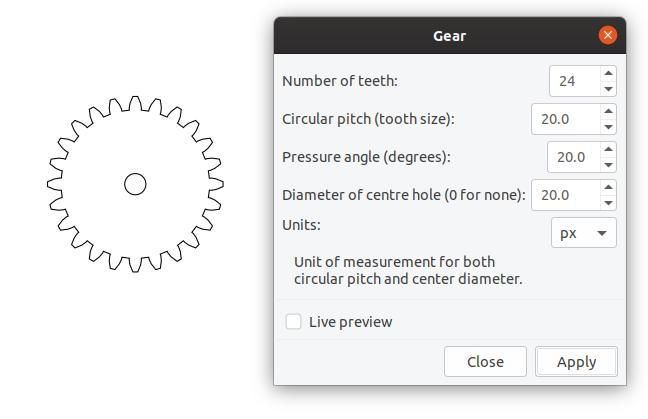
Inkscape can draw Involute gears and racks by following the menu Extensions->Render->Gear.
The dialogue and gear it drew is shown below:

The teeth are sized and shaped to engage with another gear of the same specification, this boiling down to the numbers entered in the dialogue.
Almost all modern gears are involute because they are smooth running, not effected by small spacing errors, and are easy to mass produce. Most gears are used to transmit power, and the involute form is said to be good for this – low wear, whilst careful shaping of the teeth reduces gear whine at speed. Typically a fast rotating power source is geared down to drive road wheels or a machine.
Clock gearing is arranged the other way round: a very slow turning drum powered by a spring or weight gears up to turn a relatively fast moving seconds or minute hand. Somewhere near the top of the gear train, an escapement connected to an accurate timer like a pendulum, allows the train to tick in timed steps, perhaps once per second. These ticks are divided down through another gear train to show HH : MM : SS. As clocks don't have power to spare its important to minimise friction. Cycloidal gears are said to be better for low friction than involutes, but it's not clear to me why. My admittedly weak understanding suggests involute gears should be best for everything.
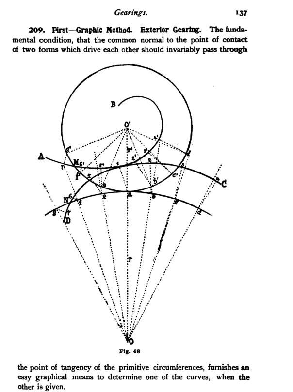
Early clock-makers knew sod-all about involutes and cycloids! Their clocks were built by eye and experience. The experience comes from looking at worn teeth, perhaps in a local water mill, because teeth tend to grind down naturally to matching curves. Craftsman copied these curves with a file to cut new teeth, avoiding the running in stage. Later on mathematicians did a proper analysis and produced the formulae needed to shape properly matching gears from first principles.
One way of making clock gears is to carefully grind a tool to fit the profile of an existing gear. (This may be essential when repairing a very old clock.) Then, with the gear blank held in a dividing head, the tool can be spun like a fly-cutter to chop teeth one by one around the circumference. A posh dividing head isn't necessary – people use old saw blades to provide the necessary indexed steps.
Making tools to cut mathematically defined curves is more challenging. Ivan Law's Gears and Gear Cutting is a good place for practical men to start – I've found the maths in engineering textbooks very difficult. You could also grind tools to match gears drawn by Inkscape.
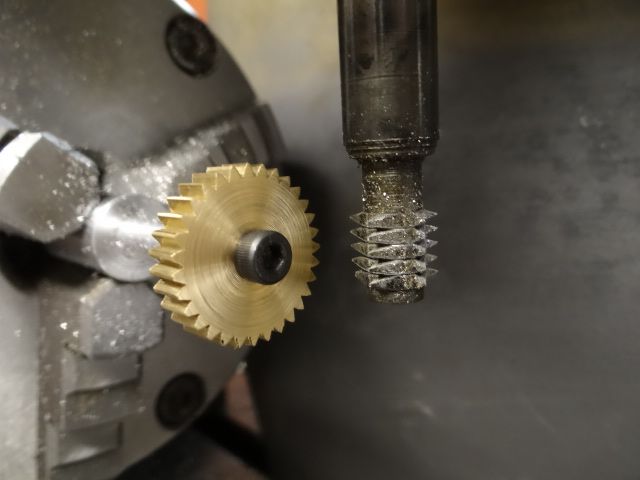
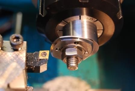
Most professional gears are made by hobbing, where a specially shaped cutter and blank are synchronised together. Or gear cutters can be bought to match the required DP(Imperial) or Modulus(Metric) : quite a lot of them may be needed. Ivan Law describes a method using buttons, and a more modern idea produces the curves by facing the new tool into the side of a cone drill. The only method I've used is this medieval home-made tool, which, despite it's crude appearance generates involutes that fit Meccano.

Hours of fun ahead!
Dave
Edit: Poxy Smileys!
Edited By SillyOldDuffer on 22/12/2019 15:16:27
 Neil Wyatt.

