Why dont we have end mill gear cutters ?

Advert

Why dont we have end mill gear cutters ?

Home Forums Beginners questions Why dont we have end mill gear cutters ?

Viewing 25 posts - 1 through 25 (of 57 total)
  • Author
    Posts
  • #261860
    BW
    Participant
      @bw

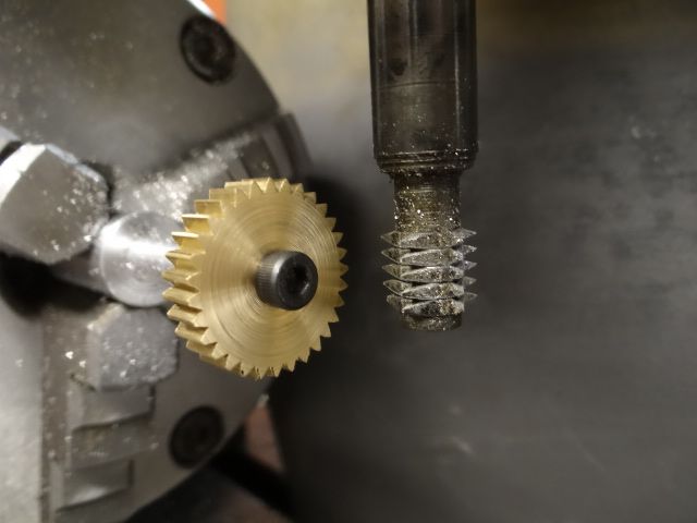
      I saw a post a while back on this forum about end mill type gear cutters.

      A bit like a corner rounding end mill cutter only it cuts the profiles between the teeth.

      Thought it was a stunning idea and am aware that somebody in USA has a patent on it .

      I reckon people must have tried diy versions but have found very few references in google – I did find on google a mention of a video by John Stevenson – is that the same chap that posts on this forum ?

      Am puzzled that I havent seen much about this in forums, blogs and old books – is it something that would impress a newbie like me but more experienced people instantly see various traps ?

      Bill

      Advert
      #8342
      BW
      Participant
        @bw
        #261866
        Martin Connelly
        Participant
          @martinconnelly55370

          Hard to sharpen compared with a basic involute gear cutter so they are likely to be throw away tools that probably cost a lot to make new. I don't think there is likely to be a big saving in set-up between an involute cutter and an involute end mill. Companies making lots of gears will hob them anyway.

          Martin

          #261867
          MW
          Participant
            @mw27036
            Posted by Bill Wood 2 on 19/10/2016 13:13:11:

            Am puzzled that I havent seen much about this in forums, blogs and old books – is it something that would impress a newbie like me but more experienced people instantly see various traps ?

            Bill

            I'd imagine it's only a matter of time before they start appearing as retail HSS tools like rounding off endmills are now. Certainly not a new idea and like you i've seen a few people use them as one off homemade style tools.

            Michael W

            #261868
            Anonymous

              Oddly enough I was reading about these type of form cutters this morning in a book by Brown and Sharpe. Specifically they were mentioned for cutting helical gears, being theoretical more accurate than using a standard involute cutter. I've thought of making one should I ever get around to using the 4-axis CNC mill to make a helical gear.

              However, there are some disadvantages. The cutters are relatively delicate; feeds and speeds are determined by the small end that is cutting the root of the gear tooth. And would you normally run an endmill at full width and double depth to form the tooth space in one pass? Second, vertical mills tend not to be as rigid as horizontals. The real killer comes down to money though. Once a shaped endmill is worn it is scrap, whereas a standard involute gear cutter can be re-sharpened many times and still retains the original shape.

              Andrew

              #261870
              colin hawes
              Participant
                @colinhawes85982

                I have an old gear cutter that is based on a tee slot type of cutter which I bought second hand many years ago but I haven't seen another one. Perhaps they are still made . Colin

                #261874
                Muzzer
                Participant
                  @muzzer

                  Haha, the idea that you could patent the notion of an end mill with a profile shape. Only in America…

                  #261880
                  Ian S C
                  Participant
                    @iansc

                    End mill gear cutters are mentioned in one of my old engineering text books (pre WW2 probably nearer WW1), it particularly says that gears of very large pitch can be cut by the end mill process, and the end mill is mounted in a horizontal milling machine. also in the same book are the Sunderland, and Fellows methods, and hobbing, also the Gleason's process for cutting spiral bevel gears.

                    Ian S C

                    #261886
                    Michael Gilligan
                    Participant
                      @michaelgilligan61133
                      #261895
                      Muzzer
                      Participant
                        @muzzer

                        I'm afraid there is no law in the US to stop people throwing money away on worthless patents – and no shortage of them in my experience. Of course, even if he somehow managed to defend his patent and actually restrict peoples use of the idea, it would only apply to the USA.

                        It probably plays well on his CV and possibly even down the pub but beyond that it's another example of how facile the US patent system really is. Just think what he could have bought using the money instead – a half reasonable gear hobbing machine perhaps.

                        #261896
                        John Haine
                        Participant
                          @johnhaine32865

                          If you read claim 1 it is highly specific and describes a method of making a cutter with a series of specific characteristics, not a profile cutter as such. Also the inventor/applicant was so proud of it that it has lapsed from non payment of fees.

                          #261897
                          Clive Foster
                          Participant
                            @clivefoster55965

                            Seriously confused patent. Zig-zags back and forth between the cutteritself and the process for making it. None of it being remotely patentable due to prior art. Such cutters have been made in the past and the manufacturing process described is common to all end-mill type form cutters. You could make a corner rounding cutter in exactly the manner described. 2003 date! Maybe its been stuck in the system since 1903.

                            From my limited experience of the US patent system its clearly broken and corrupt with no understanding of practicalities or prior art. Any system that lets things like Apples claim on rounded corners for smartphones through is beyond redemption. Theoretically you are not supposed to be able to patent anything that doesn't work, is trivial or merely a development of prior art that could have been made by any competent practitioner.

                            Getting back to the cutter itself they would probably be best used on a pre-slotted blank so the skinny bit in the middle doesn't get over-worked. For ordinary purposes its generally acceptable to make the dedendum a bit too deep and a little too wide which also helps with a stronger cutter. So long as the contacting faces follow the involute form all will be well. Form departures outside the contact area matter not at all unless the gear strength is adversely affected. Maybe cut one side of a tooth at a time to further reduce loads. its not a mass production tool anyway. Its a get out of jail, I need one by tomorrow sort of thing. Might make most sense for large gear teeth.

                            In principle it can be resharpened quite easily. You just push the profile further back up the shank until the worn area has been removed. This sort of think makes me wonder why there appear to have been no attempts to produce a small versatile CNC Tool and Cutter grinder for Home Shop and similar folk. Given suitable lateral thinking I think such could be done quite easily and not silly expensive.

                            Clive

                            #261908
                            Neil Wyatt
                            Moderator
                              @neilwyatt

                              It's the quality of the drawing I like, especially the drawing of a traditional cutter for use on a keyed spindle – no keyway and it looks more like a (dodgy) gear than a cutter!

                              Neil

                              #261909
                              Tim Stevens
                              Participant
                                @timstevens64731

                                I'm sure that Citroen, in about 1932, used end-mill type cutters to make herringbone helical gears. These were different from the 'normal'* herringbone gears (which have a pattern like a tractor tyre) as the teeth were continuous from one side of the angle to the other. So what value a later patent, I wonder?

                                * as used in Wolseley and MG and Morris gearboxes at the same period. The idea was to have quieter (ie non-deafening) intermediate gears.

                                PS it was their clever gears which were the origin of their chevron trade mark (now being abandoned it seems).

                                Cheers, Tim

                                #261935
                                John Haine
                                Participant
                                  @johnhaine32865

                                  Regarding the Apple patent on rounded corners, the US patent system has a concept of a "design patent", or what in the UK would be a registered design; as opposed to a utility patent which is more what we think of as a patent. The rounded corners, as well as a lot of other Apple patents, are design patents. The confusion of using the term "patent" for both in the US creates a huge amount of confused comment.

                                  Another point, when reading a patent start with the claims, especially claim 1. These are the statements of what the inventor is trying to protect. All the rest of it is just descriptive. Especially with US patents, which often initially have huge numbers of claims, the ones that survive in the final granted document can be very limited, with only a very small scope of protection relative to the prior art.

                                  I don't think anyone has commented here on the possibility of cutting gears with normal end mills/slot drills, as done the the "gearotic" software that JS has been involved with.

                                  #261936
                                  Steve Withnell
                                  Participant
                                    @stevewithnell34426
                                    Posted by Tim Stevens on 19/10/2016 18:49:52:

                                    I'm sure that Citroen, in about 1932, used end-mill type cutters to make herringbone helical gears. These were different from the 'normal'* herringbone gears (which have a pattern like a tractor tyre) as the teeth were continuous from one side of the angle to the other. So what value a later patent, I wonder?

                                    * as used in Wolseley and MG and Morris gearboxes at the same period. The idea was to have quieter (ie non-deafening) intermediate gears.

                                    PS it was their clever gears which were the origin of their chevron trade mark (now being abandoned it seems).

                                    Cheers, Tim

                                    The Herringbone used to feature on the bonnet of the older Citroens as a company logo, now it can be seen moulded into the radiator grill etc.

                                    #261941
                                    Bill Davies 2
                                    Participant
                                      @billdavies2

                                      As Martin states in the second post, the standard cutters (hob and gear shaper) are easier to sharpen without complicated setups, at least for shaper cutters for producing spur gears. They are sharpened on their front faces, and can be ground back until the teeth are quite thin and at risk of breaking, without affecting the tooth shape very much. They are therefore long-lasting, which the teeth on an end mill would not be.

                                      Hobs and gear shaper cutters are both produced by essentially straight sided grinding wheels. A screwcutting motion of a form tool or grinding wheel produces hobs (plus a cam action in the cross slide to provide backing off), and by involute generating movements in the case of gear shaper cutters.

                                      Furthermore, the specialised machines already exist in the market and are suitable for quantity production. Both types of gear cutting machine can be set up to produce helical gears, albeit with modified tooth form for hobs and also matching helix angle for gear shaper cutters.

                                      One-offs can be produced on a horizontal mill with an involute form cutter, using one of the typical set of eight form relieved cutters to cover the range of numbers of teeth, although only spur gears would have the correct tooth form and thickness to mesh with existing gears of matching pitch.

                                      Bill

                                      #261950
                                      John Stevenson 1
                                      Participant
                                        @johnstevenson1
                                        Posted by John Haine on 19/10/2016 21:24:51:

                                        I don't think anyone has commented here on the possibility of cutting gears with normal end mills/slot drills, as done the the "Gearotic" software that JS has been involved with.

                                        Gear hobbing is a generating process where the cutter isn't a form cutter but by the process of rolling the cutter [ or work ] around the work [ or cutter ] an involute is formed.

                                        Roughly divisible into three main types. Note I said roughly as I'm trying to keep it simple.

                                        [1] Hobbing with a straight sided helical hob that as the blank passes by the hob the involute is formed.

                                        Quick, easy to do on specialised machines but needs expensive cutter.

                                        [2] Gear shaping where a cutter in the shape of a gear is rotated round a blank which making a usually vertical shaping motion and planes the involute form into the blank.

                                        Usually more expensive to do than hobbing but has some advantages like being able to make close coupled gears that a hobber can't due to needed run out of the cutter.

                                        [3] Gear planers where the cutter is a section of rack that planes the blank whilst rotating the blank. After producing a few teeth equal to the length of the cutter it backs off, rotates and does the next set of teeth.

                                        These are ideal for large work and helical's and even herringbone gears with two cutting heads.

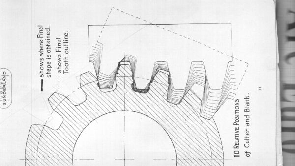
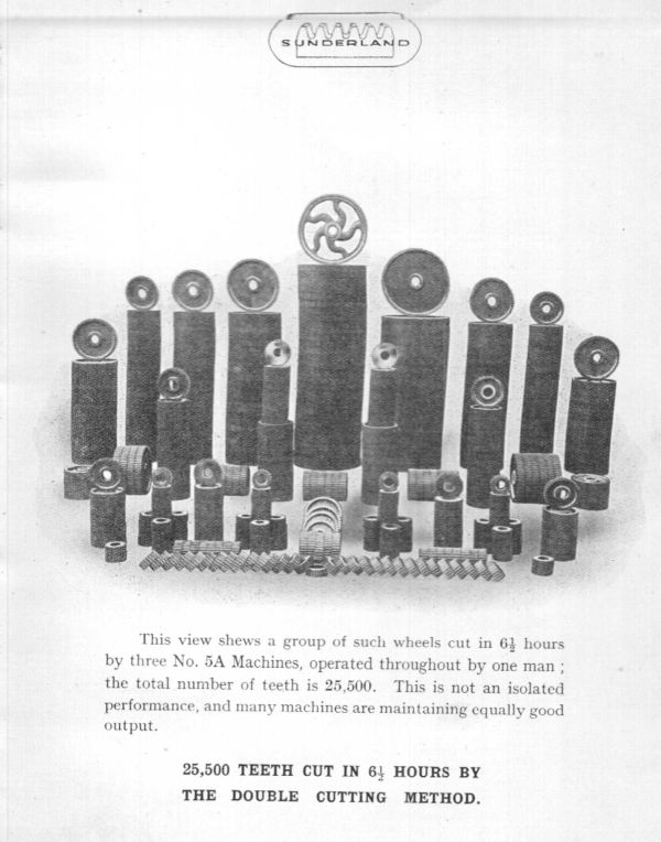
                                        It's the action of this type I want to discuss. Because the cutter is a rack it's straight sided and the rolling action caused the involute to be generated. This type of machine was invented by Sam Sunderland way back in 1895.

                                        Rather confusing as it shows the rack moving whilst the gear blank is stationary when in fact it's the opposite but has been done this way for clarity. So examining this operation and looking at just one rack flank you can see that if that flank was a normal cutter i.e. and end mill or slot drill then by varying the hight of the cutter, it's placement in the Y axis on a milling machine and the rotation of the blank held in a 4th axis [A] then that simple £2.00 cutter can mimic what a Sunderland can do. In the example about it took 11 passes to generate the teeth.

                                        Sounds slow but it's all automatic.

                                        So take away having a large purpose built machine and special cutters and substitute a bench top CNC with a £2.00 cutter and OK we are even slower working but provided that cutter can get into the tooth gullet it will cut any type of tooth shape, spur, helical, bevel and nay specials.

                                        This is where Art Fenerty come into the equation. Art after writing Mach 3 and retiring and selling it on decided to build a clock but wasn't happy with the software out there. Whilst a lot of it looks good, mathematically it's crap.

                                        So Art wrote his own called Gearotic, OK stupid name but so is Apple wink

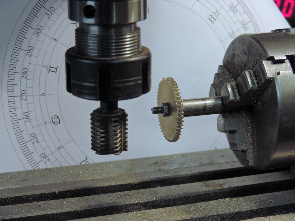
                                        By taking multiple shaving cuts after blocking out the tooth space whilst raising and moving the cutter and at the same time rotating the blank it can mimic the Sunderland gear planer.

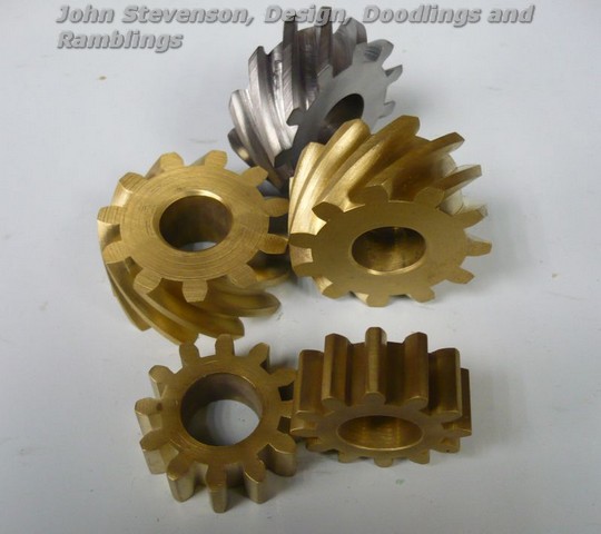
                                        A selection of 4 gears done in bronze, 2 spur and 2 helical's. The steel helical was an early iteration when Art was still working all the maths out and hadn't got the correct helix angle worked into the formulae.

                                        All done with an off the shelf 3mm cutter.

                                        You can also make specials which you can also do by any of the other generating methods listed above but not by using form cutters unless specially made.

                                        Three gears, 13, 14 and 15 teeth but all cut on the same blank. Only 14 is correct but you can mix and match these in any position.

                                        This tooth shift is often done in industry to give stronger teeth or more contact. It helps when cutting low count gears when the pressure angle is low as it stops undercut.

                                        In fact when I cut our version of the Myford screw cutting gears I cut the very popular 20 tooth on a 21 tooth blank to give a far stronger tooth, the ration believe it of not is unchanged.

                                        Standard 20T on the right, modified gear on the left.

                                        #261969
                                        Michael Gilligan
                                        Participant
                                          @michaelgilligan61133

                                          John,

                                          Thanks for that very useful post ^^^

                                          Might I just add a link to the article by 'Base Circle' on cutting gears in the shaper **LINK**

                                          http://neme-s.org/Shaper%20Books/Michael_Moore/shaper%20gear%20cut.pdf

                                          This describes a generating mechanism which [whilst described for the shaper] could be easily adapted to the verical mill.

                                          MichaelG.

                                          #261981
                                          Neil Wyatt
                                          Moderator
                                            @neilwyatt
                                            Posted by John Stevenson on 20/10/2016 00:52:31:

                                            cutting gear.jpg

                                            jovilabe (6).jpg

                                            Essentially the same process, gears cut with a rack form hob. There are two pairs of 53:33 (total 86) and two of 50:40 (90 teeth) in there, using the spacing for 88 teeth by being cut on under/oversize blanks and they work just fine without fettling. Also other pairs cut using a PCD +/- up to 2 teeth.

                                            #262003
                                            Anonymous
                                              Posted by John Stevenson on 20/10/2016 00:52:31:

                                              It's the action of this type I want to discuss. Because the cutter is a rack it's straight sided and the rolling action caused the involute to be generated. This type of machine was invented by Sam Sunderland way back in 1895.

                                              Rather confusing as it shows the rack moving whilst the gear blank is stationary when in fact it's the opposite but has been done this way for clarity.

                                              I don't follow that; surely both the blank and the rack cutter need to move as if they're in mesh, as well as the cutter reciprocating along the axis of the gear blank? If the rack just reciprocated and the blank rotated, you'd end up making a plain cylinder. Towards the end of this video you can plainly see the cutter being retracted and moved down what looks like one tooth space:

                                              **LINK**

                                              I must have another go with Gearotic; on my old computer it crashed and burned when I tried a helical gear. Now I have a new sooper dooper computer it might be better. There is one thing that looks slightly odd about the helical gears generated by Gearotic. It may just be the way the picture was taken, but the chordal arc of the tooth and space look to be different; I would have expected them to be the same?

                                              Having disagreed with JohnS twice in one day I now await my excommunication message. sad

                                              Andrew

                                              #262008
                                              SillyOldDuffer
                                              Moderator
                                                @sillyoldduffer

                                                And Duffer's Mk1 patent Medieval version:

                                                dsc03599.jpg

                                                Seriously though, Neil pointed out in another thread that I'd over-relieved the teeth on this one. Quite right.

                                                Nonetheless I successfully used the cutter to make eight aluminium and two brass gears, each 1/4" across. The cutter is still sharp but a careful look at the picture shows that one of the lower teeth has lost it's tip. I expect more damage later this afternoon when I try it on a steel blank.

                                                I'm impressed by this method. The cutter is a lot easier to make than an equivalent form tooth for fly-cutting.

                                                Dave

                                                #262013
                                                Roderick Jenkins
                                                Participant
                                                  @roderickjenkins93242
                                                  Posted by SillyOldDuffer on 20/10/2016 12:14:24:

                                                  I'm impressed by this method. The cutter is a lot easier to make than an equivalent form tooth for fly-cutting

                                                  Agreed. I see how this method works for a gear with a large number of teeth, even the Brown & Sharpe cutters assume that anything greater than 135 is the same as a rack. I can also see that the interference from the cutting teeth modify the form either side of the primary horizontal tooth and would be sufficient to give a good form for teeth down to, say, 60. Does anybody have a formula for calculating the adjustment required either side of the horizontal to give a good approximation to the involute down to e.g. 16 teeth? How does a Sunderland shaper do that?

                                                  Cheers,

                                                  Rod

                                                  #262018
                                                  Michael Gilligan
                                                  Participant
                                                    @michaelgilligan61133

                                                    Rod,

                                                    I think the 'Base Circle' link that I posted might help your understanding.

                                                    MichaelG.

                                                    #262515
                                                    John Stevenson 1
                                                    Participant
                                                      @johnstevenson1

                                                      First 5 minutes of this video are quite entertaining and not all outside the realms of a home workshop with a 4 axis CNC.

                                                      https://www.youtube.com/watch?v=tqaQ-sD2rBs

                                                    Viewing 25 posts - 1 through 25 (of 57 total)
                                                    • Please log in to reply to this topic. Registering is free and easy using the links on the menu at the top of this page.

                                                    Advert

                                                    Latest Replies

                                                    Home Forums Beginners questions Topics

                                                    Viewing 25 topics - 1 through 25 (of 25 total)
                                                    Viewing 25 topics - 1 through 25 (of 25 total)

                                                    View full reply list.

                                                    Advert

                                                    Newsletter Sign-up