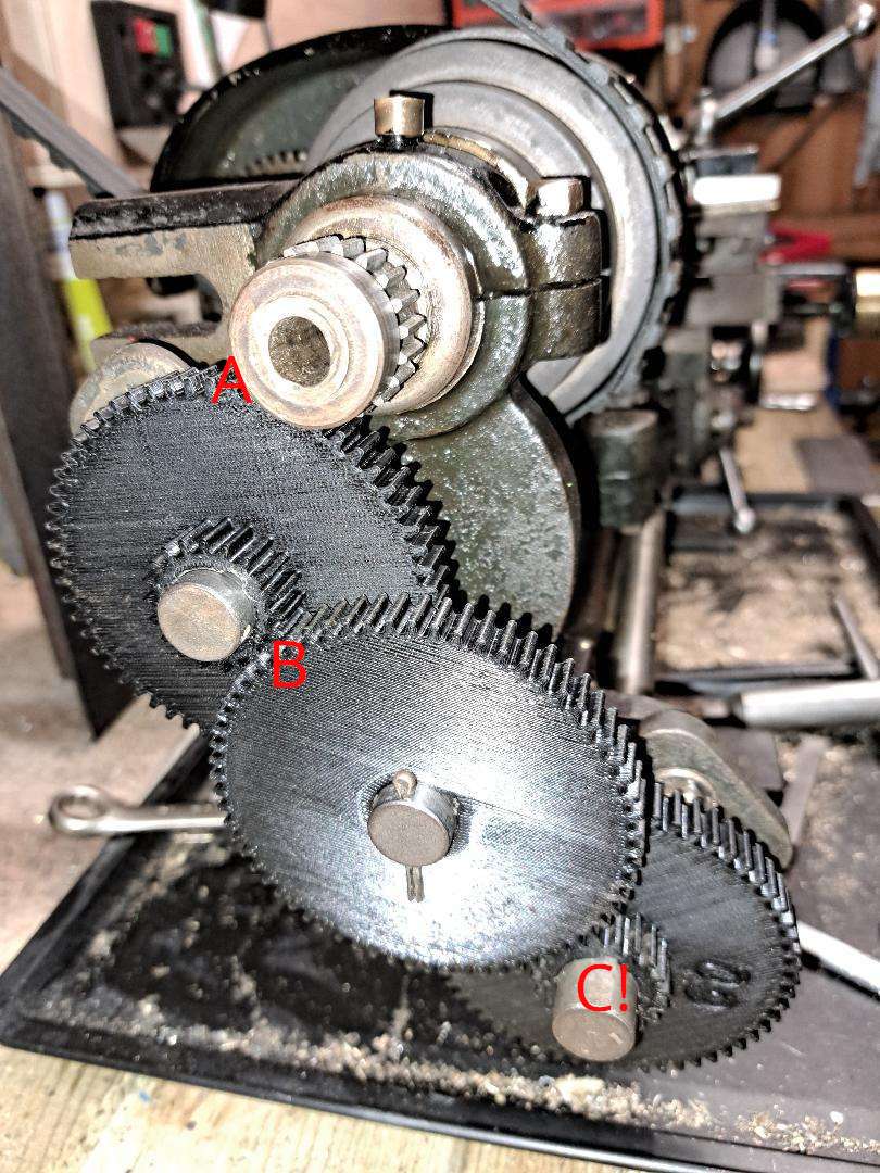
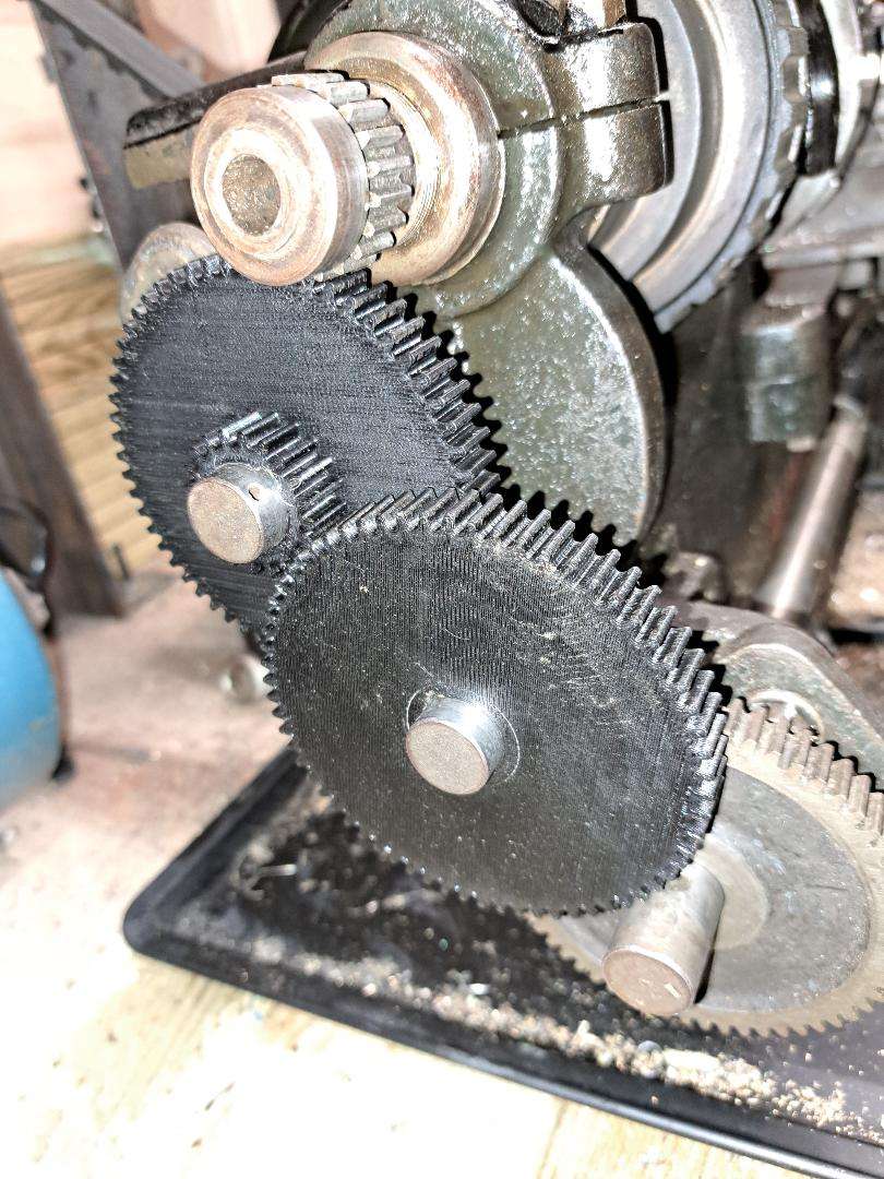
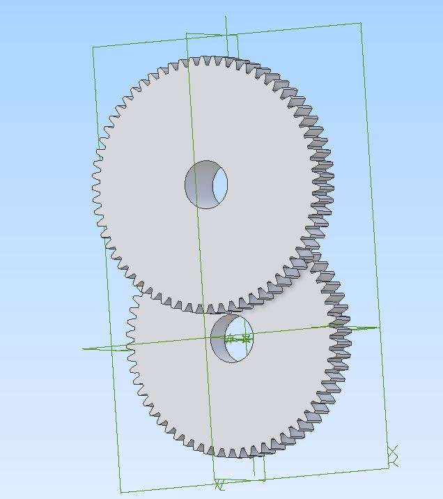
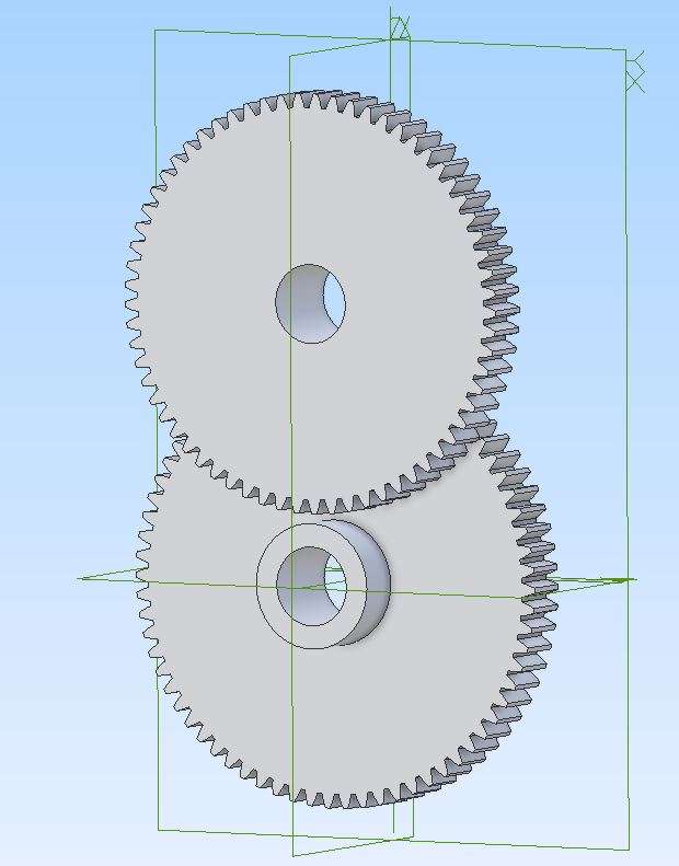
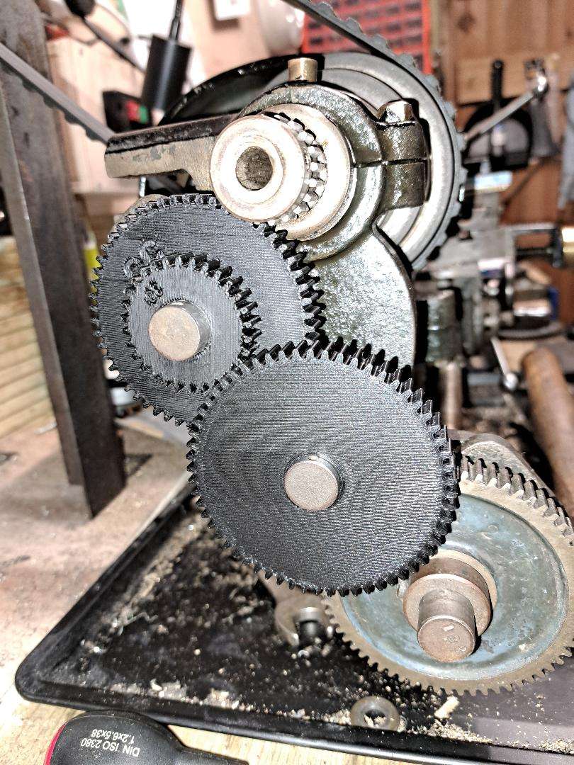
Myford ml2/3 change gears
Myford ml2/3 change gears
- This topic has 16 replies, 6 voices, and was last updated 15 February 2025 at 20:31 by
 barry.

- Please log in to reply to this topic. Registering is free and easy using the links on the menu at the top of this page.
Latest Replies
-
- Topic
- Voices
- Last Post
-
-
Bit of a con or sharp practice on water filters.
Started by:
Robert Atkinson 2
in: The Tea Room
- 15
-
18 February 2025 at 23:42
Nigel Graham 2
-
Are Stan Bray’s Optical centre punch dimensions correct?
Started by:
Andrew Tinsley
in: Workshop Tools and Tooling
- 2
-
18 February 2025 at 21:23
Andrew Tinsley
-
Vickers Inverted Engine
1
2
Started by:
JasonB
in: Stationary engines
- 10
-
18 February 2025 at 20:32
Andrew Crow
-
Unimat SL renovation – any tips?
Started by:
rjenkinsgb
in: Manual machine tools
- 1
-
18 February 2025 at 20:29
rjenkinsgb
-
NEW LOOK – Model Engineer & Workshop
1
2
…
5
6
Started by:
sohara
in: Model Engineer & Workshop
- 44
-
18 February 2025 at 20:02
Michael Gilligan
-
Heavier Spindle on Fox Alien
Started by:
IanT
in: CNC machines, Home builds, Conversions, ELS, automation, software, etc tools
- 4
-
18 February 2025 at 19:52
IanT
-
Raglan vertical milling machine
Started by:
roger kerry
in: Manual machine tools
- 5
-
18 February 2025 at 19:52
geoff warner 1
-
Clock Repair is my passion
Started by:
simonhenry700
in: Introduce Yourself – New members start here!
- 7
-
18 February 2025 at 18:56
Plasma
-
Searching for 125mmish cast iron handweels with 1″ bore
Started by:
pgrbff
in: Workshop Tools and Tooling
- 7
-
18 February 2025 at 18:12
Grizzly bear
-
Lead-sheathed wiring – why?
1
2
Started by:
gerry madden
in: Materials
- 23
-
18 February 2025 at 16:30
Stuart Smith 5
-
Milling machine advice circa £2500
Started by:
aytact
in: Beginners questions
- 8
-
18 February 2025 at 15:05
duncan webster 1
-
Can a metric baby do imperial?
1
2
3
4
Started by:
beeza650
in: Beginners questions
- 29
-
18 February 2025 at 10:37
Graham Meek
-
Magnetic optical punch
1
2
Started by:
Fulmen
in: Workshop Tools and Tooling
- 10
-
17 February 2025 at 18:39
Fulmen
-
Toolmakers clamps
Started by:
Wade Beatty
in: Workshop Tools and Tooling
- 5
-
17 February 2025 at 16:33
Martin Connelly
-
Securing smokebox number plate
Started by:
Derek Drover
in: General Questions
- 8
-
17 February 2025 at 15:01
duncan webster 1
-
Taig lathe DC motor
Started by:
Peter Cook 6
in: Work In Progress and completed items
- 8
-
17 February 2025 at 13:36
Peter Cook 6
-
Archive access going forward
Started by:
Peter Cook 6
in: Subscription issues and Digital magazines
- 6
-
17 February 2025 at 13:36
Michael Gilligan
-
Mens Shed
Started by:
Simon Neath 2
in: General Questions
- 11
-
17 February 2025 at 12:50
modeng2000
-
A New Scam Format?
Started by:
Nigel Graham 2
in: The Tea Room
- 7
-
17 February 2025 at 11:09
Dave Halford
-
Retrofitting Houses
Started by:
Michael Gilligan
in: The Tea Room
- 1
-
17 February 2025 at 10:39
Michael Gilligan
-
Meddings Overhaul – missing parts
Started by:
Woodlikesbikes
in: Manual machine tools
- 9
-
17 February 2025 at 08:54
Michael Gilligan
-
Diamond Wheel dressing attachment
Started by:
David George 1
in: Help and Assistance! (Offered or Wanted)
- 10
-
17 February 2025 at 08:36
ryan.carter848
-
Electric Car Battery Retention
1
2
3
Started by:
Vic
in: The Tea Room
- 26
-
16 February 2025 at 22:42
not done it yet
-
ML7 cross-slide problem
Started by:
Mike Joseph
in: Workshop Tools and Tooling
- 4
-
16 February 2025 at 19:04
Mike Joseph
-
Kity W oodwork Machine Switch Again
1
2
Started by:
Clive B 1
in: Website Questions, Comments, and Suggestions
- 8
-
16 February 2025 at 18:20
noel shelley
-
Bit of a con or sharp practice on water filters.
Latest Issues


Newsletter Sign-up
Latest Replies
- Bit of a con or sharp practice on water filters.
- Are Stan Bray’s Optical centre punch dimensions correct?
- Vickers Inverted Engine
- Unimat SL renovation – any tips?
- NEW LOOK – Model Engineer & Workshop
- Heavier Spindle on Fox Alien
- Raglan vertical milling machine
- Clock Repair is my passion
- Searching for 125mmish cast iron handweels with 1″ bore
- Lead-sheathed wiring – why?

