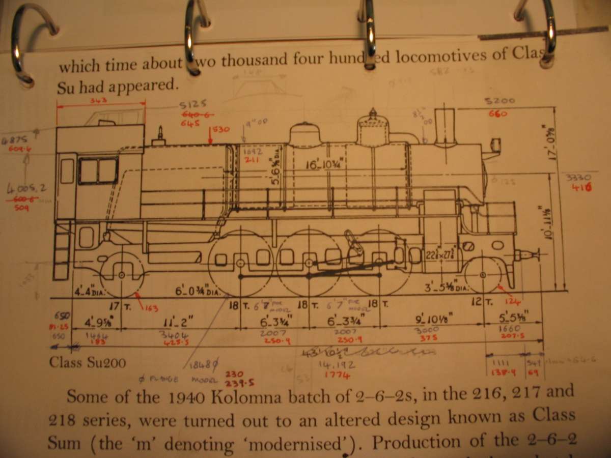
Su251-53
Su251-53
- This topic has 6 replies, 4 voices, and was last updated 13 February 2025 at 15:30 by
 parovoz.
- Please log in to reply to this topic. Registering is free and easy using the links on the menu at the top of this page.
Latest Replies
-
- Topic
- Voices
- Last Post
-
-
More Lidl questions
1
2
Started by:
old mart
in: Hints And Tips for model engineers
- 17
-
13 February 2025 at 16:42
Andy Stopford
-
The March of Technology
Started by:
John Purdy
in: Electronics in the Workshop
- 14
-
13 February 2025 at 16:00
John Haine
-
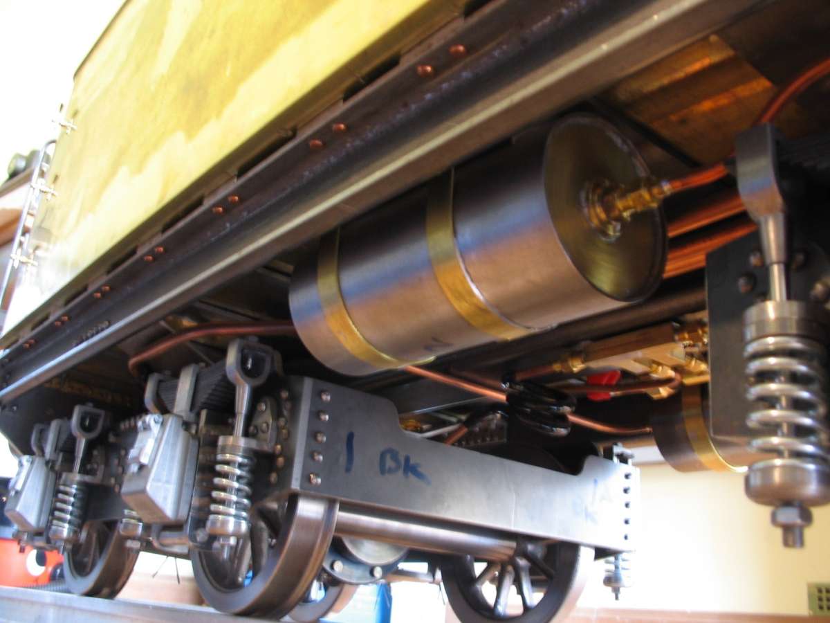
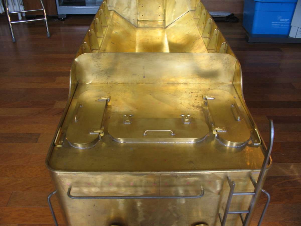
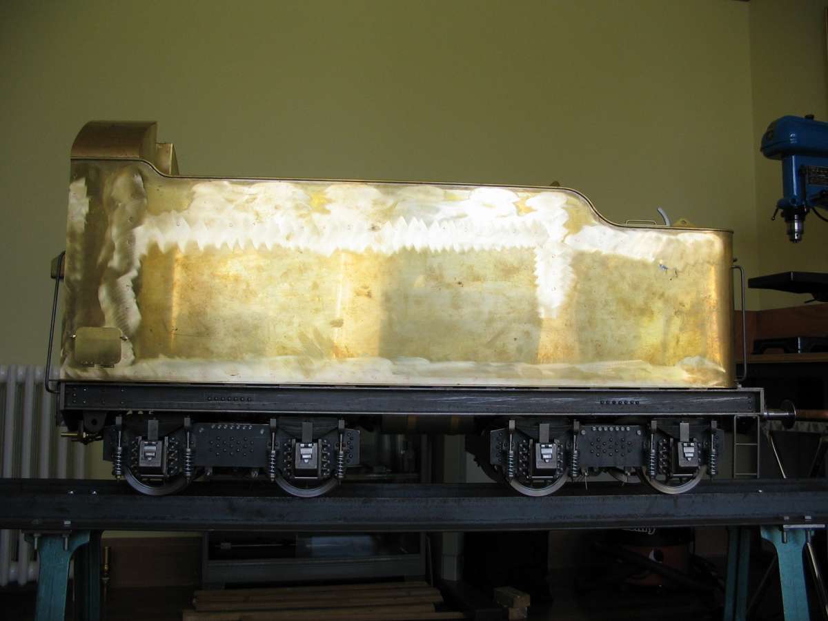
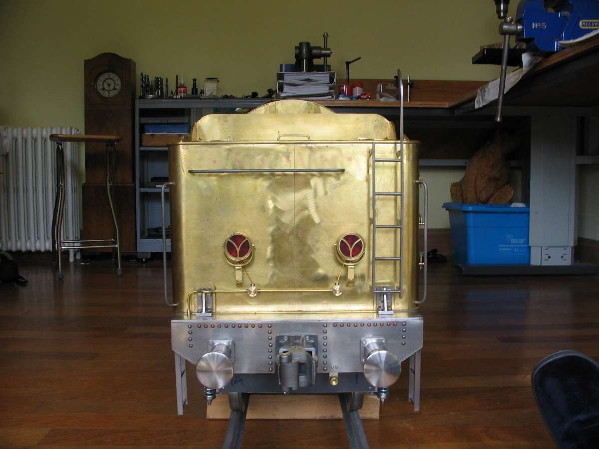
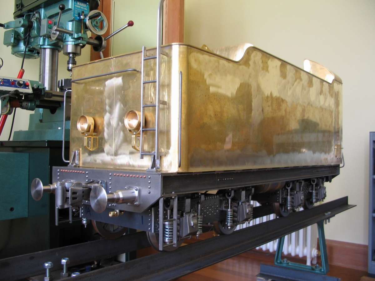
Su251-53
Started by:
parovoz
in: Locomotives
- 4
-
13 February 2025 at 15:30
parovoz
-
Electric Car Battery Retention
1
2
Started by:
Vic
in: The Tea Room
- 20
-
13 February 2025 at 15:21
jimmy b
-
Magnetic optical punch
1
2
Started by:
Fulmen
in: Workshop Tools and Tooling
- 10
-
13 February 2025 at 15:14
Michael Gilligan
-
Crimson lake royal Scot
Started by:
Michael Callaghan
in: General Questions
- 7
-
13 February 2025 at 13:47
david homer
-
Emco Mentor Wien Motor, missing ID plate, What voltage?
Started by:
Ian P
in: Manual machine tools
- 10
-
13 February 2025 at 13:47
Russell Eberhardt
-
Just discovered the site & joined.
Started by:
rjenkinsgb
in: Introduce Yourself – New members start here!
- 5
-
13 February 2025 at 13:36
noel shelley
-
Bob Rolph Engineering tutor
Started by:
Bob Rolph
in: Introduce Yourself – New members start here!
- 4
-
13 February 2025 at 12:42
Tony Pratt 1
-
Can a metric baby do imperial?
1
2
Started by:
beeza650
in: Beginners questions
- 21
-
13 February 2025 at 11:52
Graham Meek
-
CAD – Target Enigma
1
2
3
4
Started by:
SillyOldDuffer
in: CAD – Technical drawing & design
- 18
-
13 February 2025 at 11:45
SillyOldDuffer
-
PocketMags Latest Issues
Started by:
doubletop
in: Subscription issues and Digital magazines
- 5
-
13 February 2025 at 11:02
noel shelley
-
Eastern European Steam
Started by:
parovoz
in: Introduce Yourself – New members start here!
- 11
-
13 February 2025 at 11:01
parovoz
-
Hemingway Kits
Started by:
James Hall 3
in: General Questions
- 12
-
13 February 2025 at 09:24
SillyOldDuffer
-
Where to sell a Lathe ?
Started by:
Justin Thyme
in: General Questions
- 7
-
13 February 2025 at 08:38
jaCK Hobson
-
Diamond Wheel dressing attachment
Started by:
David George 1
in: Help and Assistance! (Offered or Wanted)
- 1
-
13 February 2025 at 08:19
David George 1
-
24cc DIESEL ENGINE FROM SOLID
Started by:
dean clarke 2
in: I/C Engines
- 7
-
13 February 2025 at 06:23
Diogenes
-
Homemade Headstock Lathe 1 fondry work
Started by:
celso ari schlichting
in: General Questions
- 2
-
12 February 2025 at 21:49
Nigel Graham 2
-
Neutriks
Started by:
Michael Gilligan
in: Electronics in the Workshop
- 5
-
12 February 2025 at 21:45
Nigel Graham 2
-
How to identify a thread, ACME vs TR
1
2
Started by:
moonman
in: Beginners questions
- 18
-
12 February 2025 at 20:55
moonman
-
Taylor Hobson cutter grinder modificaton
1
2
Started by:
David George 1
in: Workshop Tools and Tooling
- 9
-
12 February 2025 at 19:48
David George 1
-
Metal Lathe Centering Roller Tool for chucked item
Started by:
Blue Heeler
in: Hints And Tips for model engineers
- 9
-
12 February 2025 at 18:15
Trevor Howley
-
LBSC Dot/Diana Cylinder Castings
Started by:
Roger Hahn
in: Materials
- 7
-
12 February 2025 at 11:57
Roger Hahn
-
Family tree prog
1
2
Started by:
JimmieS
in: The Tea Room
- 15
-
12 February 2025 at 11:06
Nicholas Farr
-
Pre-war Italian thread ?
Started by:
Tim Stevens
in: Help and Assistance! (Offered or Wanted)
- 13
-
12 February 2025 at 10:32
Martin Connelly
-
More Lidl questions
1
2


