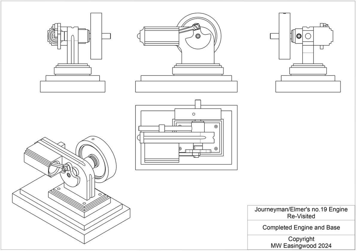
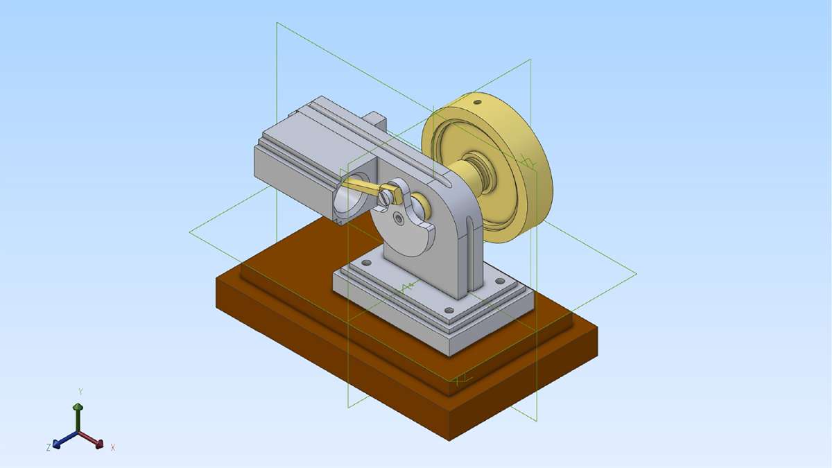
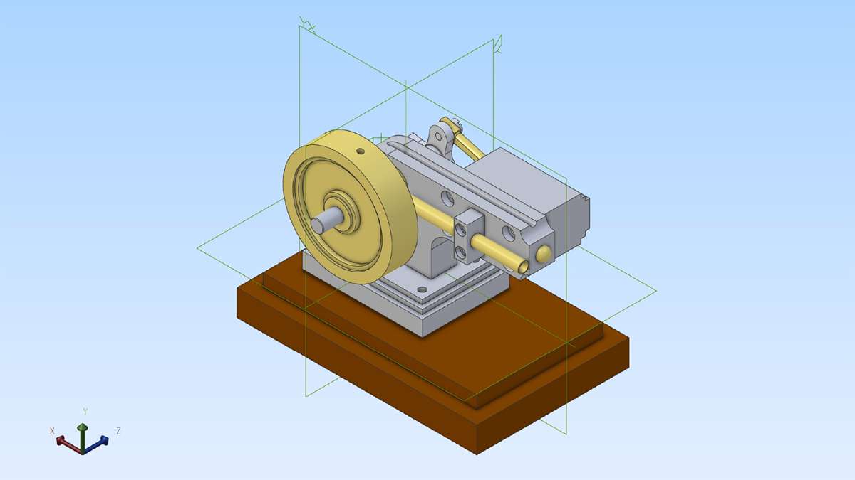
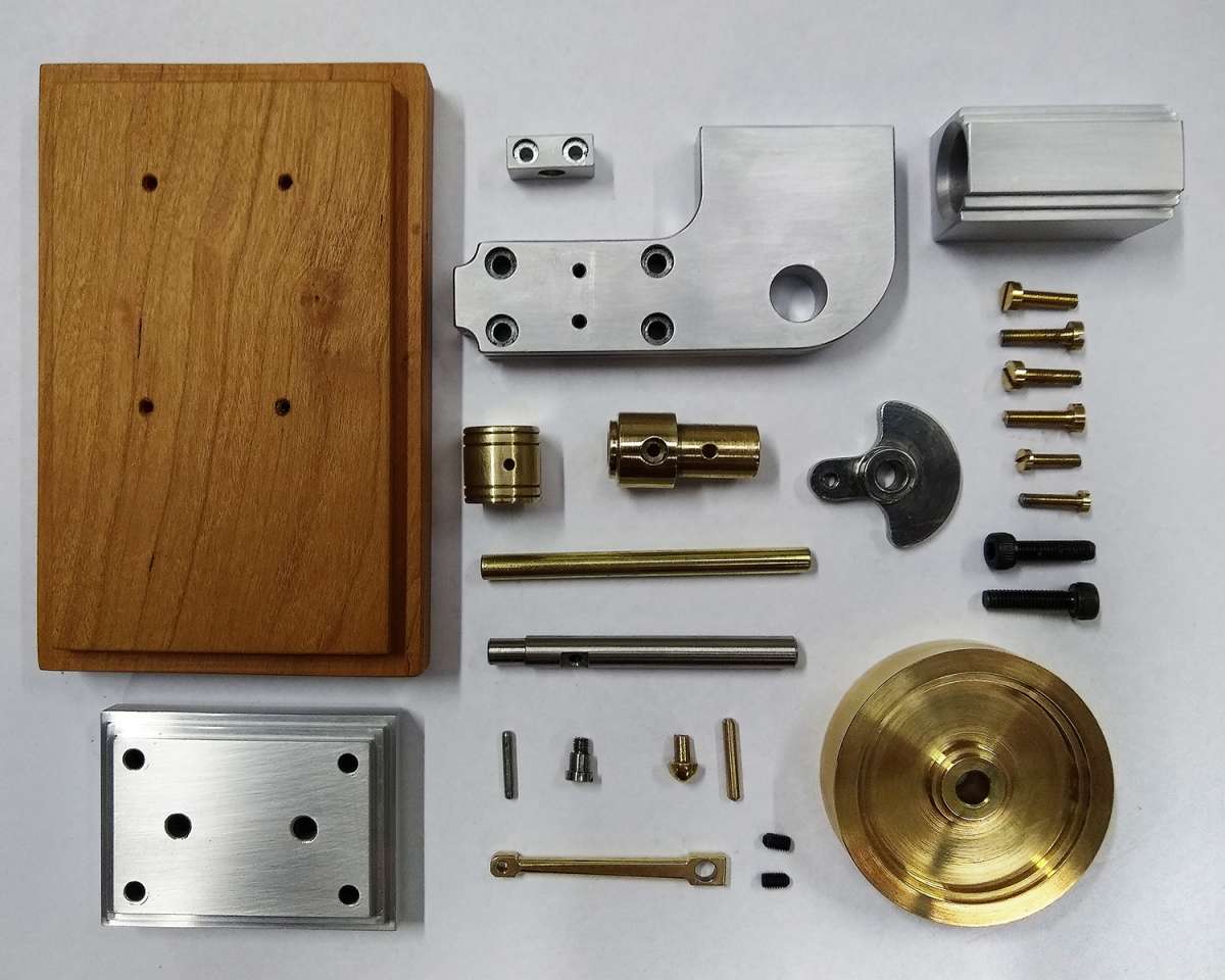
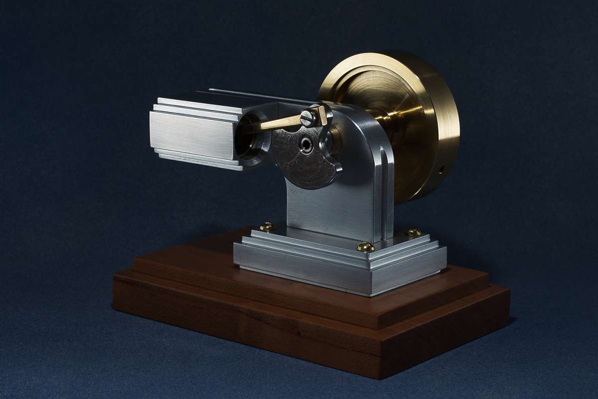
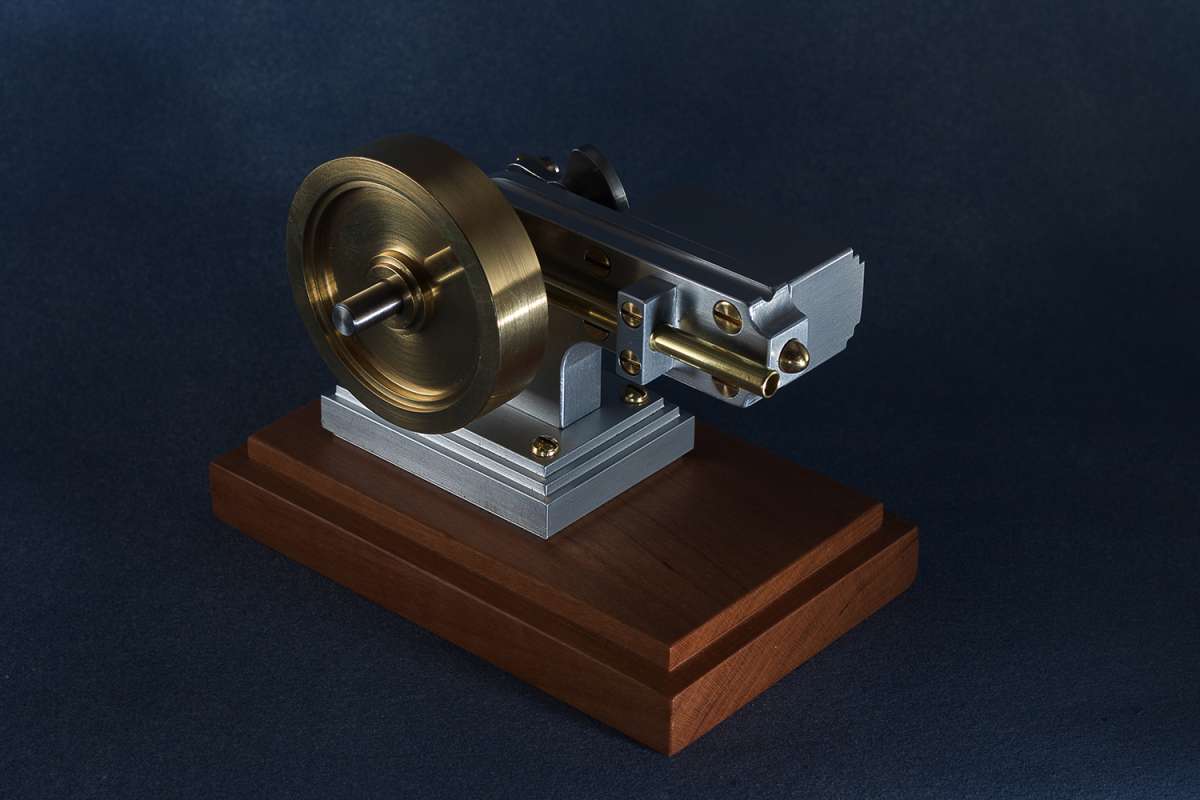
Elmer’s No.19 (Art Deco Version)
Elmer’s No.19 (Art Deco Version)
- This topic has 13 replies, 11 voices, and was last updated 30 September 2024 at 07:29 by
 Blue Heeler.
- Please log in to reply to this topic. Registering is free and easy using the links on the menu at the top of this page.
Latest Replies
-
- Topic
- Voices
- Last Post
-
-
Machinery Handbook
1
2
Started by:
Dalboy
in: Books
- 31
-
6 April 2025 at 12:03
Michael Gilligan
-
Steam pressure using thermistor
Started by:
michael howarth 1
in: General Questions
- 1
-
6 April 2025 at 11:59
michael howarth 1
-
Chester DB10LB Lathe – Not starting
Started by:
David Deaville
in: General Questions
- 3
-
6 April 2025 at 11:47
Dave Halford
-
Which type of single phase motors are best for constant use – power hacksaw
Started by:
ell81
in: Beginners questions
- 5
-
6 April 2025 at 11:44
Clive Foster
-
James Coombes Drawing Error (or mine?)
Started by:
Steve Withnell
in: Drawing Errors and Corrections
- 5
-
6 April 2025 at 11:42
Dave Halford
-
Supply company catalogues
Started by:
nevillet
in: Workshop Tools and Tooling
- 5
-
6 April 2025 at 11:39
noel shelley
-
Flattening brass plates
Started by:
t1krt
in: Workshop Techniques
- 6
-
6 April 2025 at 11:03
Dave Halford
-
Stripped aluminum threads. Now what?
1
2
Started by:
brucemc777
in: Beginners questions
- 19
-
6 April 2025 at 10:39
howardb
-
Problem getting the right parameters on a VFD
Started by:
Robert Graham
in: Electronics in the Workshop
- 7
-
6 April 2025 at 10:26
Robert Graham
-
Damp proofing concrete floors
Started by:
Duff Machinist
in: General Questions
- 13
-
6 April 2025 at 02:52
Duff Machinist
-
Measuring increments on boring head
Started by:
Bill Phinn
in: Workshop Techniques
- 15
-
5 April 2025 at 20:50
JasonB
-
Elliott Omnimill Quill Clamp
Started by:
dangermouse
in: Manual machine tools
- 4
-
5 April 2025 at 20:27
Paul Kemp
-
How to wire up 3 phase motor and 3 phase converter?
Started by:
ell81
in: Beginners questions
- 7
-
5 April 2025 at 18:36
Robert Atkinson 2
-
Morse Key
Started by:
Steve Withnell
in: Work In Progress and completed items
- 3
-
5 April 2025 at 18:20
Mike Hurley
-
My week this week! My workshop videos
1
2
…
11
12
Started by:
Phil Whitley
in: The Tea Room
- 14
-
5 April 2025 at 16:00
Phil Whitley
-
Myford S7 Taistock Adjustment
Started by:
Harry Wilkes
in: General Questions
- 9
-
5 April 2025 at 15:17
Harry Wilkes
-
Flexispeed Meteor 2
Started by:
ferroequinologist
in: Manual machine tools
- 11
-
5 April 2025 at 07:01
ferroequinologist
-
What Did You Do Today 2025
1
2
3
4
Started by:
JasonB
in: The Tea Room
- 23
-
4 April 2025 at 20:57
Nigel Graham 2
-
Powered hacksaw – blade lift for the return stroke
Started by:
Sonic Escape
in: General Questions
- 8
-
4 April 2025 at 20:00
Nicholas Farr
-
New member old lathe
Started by:
t1krt
in: Introduce Yourself – New members start here!
- 8
-
4 April 2025 at 19:52
t1krt
-
Tangential tooling
1
2
Started by:
Keith Matheson
in: Workshop Tools and Tooling
- 13
-
4 April 2025 at 18:14
Howard Lewis
-
Which lathes have drawbars in the headstock?
1
2
Started by:
ell81
in: Beginners questions
- 17
-
4 April 2025 at 18:04
Howard Lewis
-
gear cutting with the shaper
Started by:
jacques maurel
in: Workshop Techniques
- 5
-
4 April 2025 at 15:15
Andrew Tinsley
-
Electric motor vibrations
Started by:
Sonic Escape
in: General Questions
- 8
-
4 April 2025 at 07:38
JasonB
-
Build Your Own Metal Working Shop From Scrap (7 book series)
Started by:
Dr_GMJN
in: Books
- 6
-
4 April 2025 at 06:39
Pete
-
Machinery Handbook
1
2
Latest Issue
Newsletter Sign-up
Latest Replies
- Machinery Handbook
- Steam pressure using thermistor
- Chester DB10LB Lathe – Not starting
- Which type of single phase motors are best for constant use – power hacksaw
- James Coombes Drawing Error (or mine?)
- Supply company catalogues
- Flattening brass plates
- Stripped aluminum threads. Now what?
- Problem getting the right parameters on a VFD
- Damp proofing concrete floors

