We have had an excellent ‘crop’ of entries for this year’s Stevenson Trophy – the workshop equipment competition where readers get to choose the winner yourselves.
In fact, we had so many entries, that we have had to strictly apply the 500-word limit and limit the number of photographs (entries with fewer words got an extra photo!).
Readers and Model Engineer Forum members can vote up until the 30 September using the link here COMPETITION VOTE. The result will appear in the November issue of MEW, and we hope to award the trophy at this year’s Midlands Model Engineering Exhibition in October.
Enjoy more Model Engineer reading in the monthly magazine.
Click here to subscribe & save.
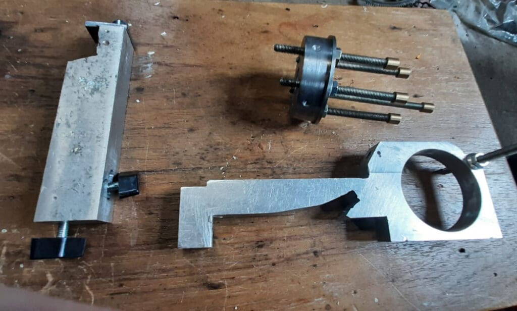
Lathe Saddle Stop – Alan Girvan
I have been wanting a lathe saddle stop for quite a while and there have been quite a lot of excellent examples in Model Engineers’ Workshop. However the problem I had with them was that they all bolted to the rear of the lathe. My lathe is fairly tight to the wall which makes it difficult to access and I am sure there are lots of other hobbyists who just don’t have the space to have their lathe sitting out from the wall for access either. So I decided I would try and cobble together something I could bolt onto the front of the lathe without drilling or making alterations to the bed of the lathe.
After a lot of pondering and thought I came up with this. It is a five-station saddle stop, I tried to make it a six station but it turned out to be a failure, so I decided to start again with a five stop and this time I got it to work. I have been using this for about four years now and it has done everything I wanted it to do. I am sure there are lots of people out there who will improve on the design and probably turn it into a six stop. I have found it very easy to use. Whenever you have finished with it you can take the centre out and leave the frame in situ so when you need it again you just have to push it in.
Vote using the link here COMPETITION VOTE.
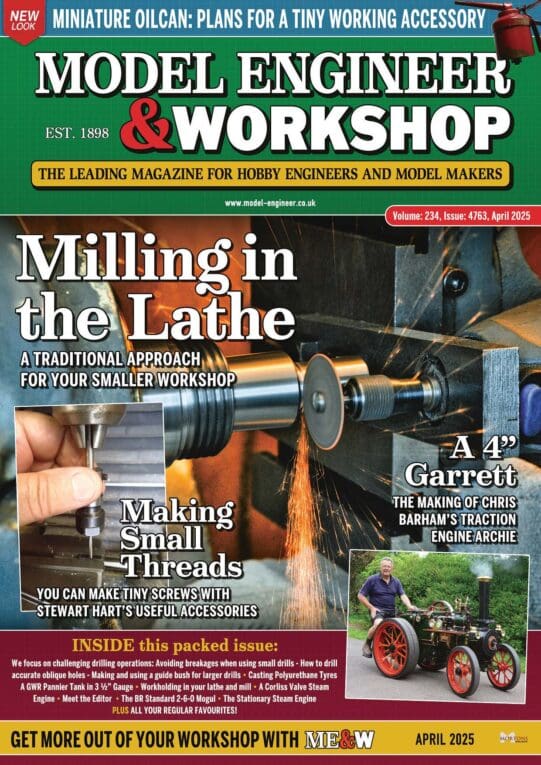
Eccentric Chuck – Bernard Towers
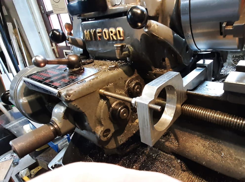
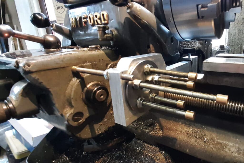
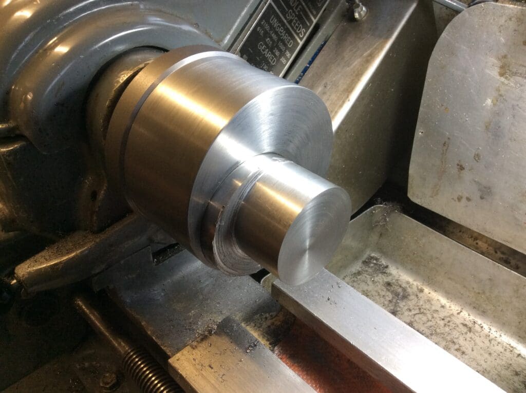
As I Spend some of my workshop time making small ic engines the thought of having a nice bit of tooling for doing the crankpins as I prefer to have them integral rather than pressed in place. After a bit of investigation it seems eccentric chucks are the thing of dreams for the home workshop so pencil and cigarette packet drawing started. The one I have made is 4”od but is still a heavy piece of kit and even though a lot of metal is removed from the main body you then fill it with the adjustable part so essentially its solid with anER 25 collet nose out front. I’m sure that this weight adds to the ability to get a good finish on your parts.
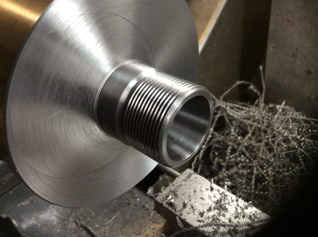
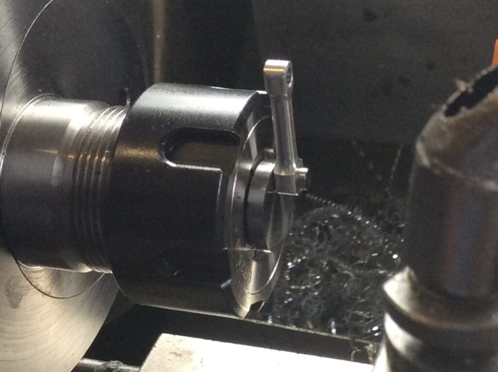
This can obviously be made with a backplate of your own choosing, mine just happens to be Myford. The adjustable part is locked/unlocked by a George Thomas type used on his pillar tool design. This hole has to be machined first and a piece of brass bolted in place. It is not difficult to make but produces a lot of swarf as a 2 1/2” hole has to be bored through the 4” x 2” blank which is eccentric by 1 1/4”.
With your 2 1/2” x 3 1/2”long blank fitted into the bored hole the ER or whatever style nose you like can be machined on the front, it does involve a fair bit of interrupted cutting.The tapers and threads you use is up to you but keep the tolerances as tight as you can, mine has a commercial ER25 bb nut and I used that as the thread gauge. It is possible to have a crankshaft up to 4” long in the chuck something which is difficult with a 4 jaw and small bore lathe and if using a Keats jig would leave a lot of overhang. It is set by using a Dial gauge with a piece of smooth flat steel screwed to the plunger at right angles allowing the chuck with dowel installed to read the stroke of the chuck. I have a hole drilled in the adjustable part to allow a pin spanner to be used to help with the adjustment.
Vote using the link here COMPETITION VOTE.
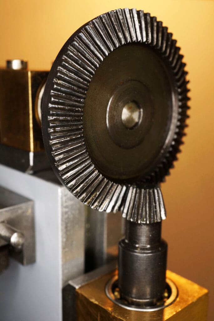
Bevel Gear Test Rig – Bob Reeve
Work started late in 2018 to improve the quality of bevel gears produced in model engineers’ workshops. These were parallel bevels, rather than the fully formed versions produced commercially. The starting point was a pair of 1:1 Mod 0.5 bevels made without the errors already identified by others. This rapidly led to the realisation that some means of comparing the performance of the bevels was required. At which time the Covid pandemic appeared with its associated restrictions. What follows can be considered a child of the Lockdown!
The development work was documented in a series of MEW articles, starting with four parts of “Bob’s Better Bevels” (MEW 316). A very crude test rig was devised which identified the features needed to get more meaningful results, including better bearings, accurate shaft alignment and easy adjustment of meshing.
In parallel with this was considerable theoretical work (and maths) to identify where approximations inherent in the current methodology could be improved. The second-generation test rig had all the extra features identified above, plus the unintended additional capability of sustained high-speed running for noise and vibration evaluation.
The theoretical evaluation of the geometry indicated that tooth separation was excessive and some angles were not ideal. Bevels cut with a revised geometry were better, but really needed CNC machining to achieve the more complex geometry reliably (MEW 319). It also necessitated an accurate means of adjusting the mesh. The criteria being that gears should mesh without binding, with minimal backlash but must not bottom out at the root of the tooth.
The third iteration of the test rig included micrometer meshing adjustments (40 tpi), providing optimised meshing by “feel”. The rig was also fitted with a short rubber coated torque reaction bar to locate in the T-slots of my CNC mill which provided the variable speed drive for the rig (MEW 319). By this time the bevels had progressed from 1:1 to 4:1 (MEW 312). Such bevels were more demanding in terms of the precision required to manufacture them. The dial gauge assessing concentricity was calibrated in microns and setting cone angles on the lathe utilised a sine bar to get the correct angle.
The revised rig worked well, but only after one of the shafts was replaced due to run out. The tests were now exceeding 10,000 rpm on the o/p shaft, while the handle was used for low-speed evaluation using engineers’ blue. The latter showing up some unexpected faults still present, and the former showed noise levels dominated by resonances in the assembly.
Finally, a pair of 4:1 bevels was produced which I considered satisfactory. No binding and minimal backlash; not quite instrument quality, but much improved. The SMEE stand at MMEX 2022 exhibited the test rig, together with an automotive differential using some of the gears produced (MEW 331).
Could it be further developed? It should be possible to include a measuring datum so that optimal meshing could be transferred with pre-determined shim sizes.
Vote using the link here COMPETITION VOTE.
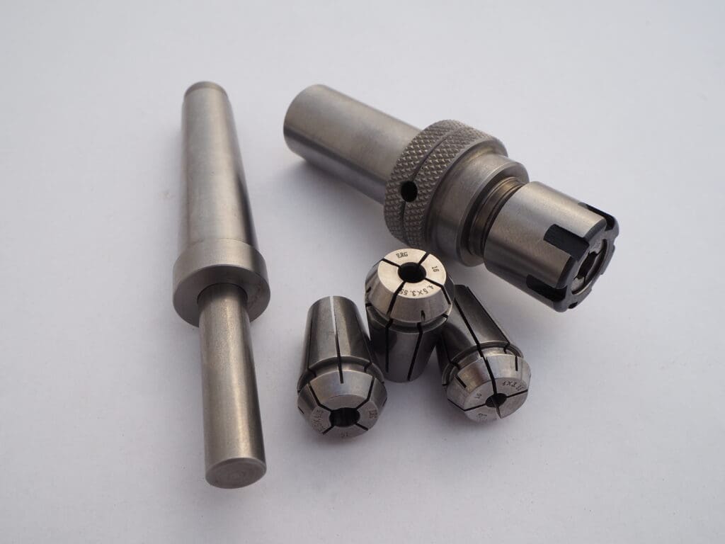
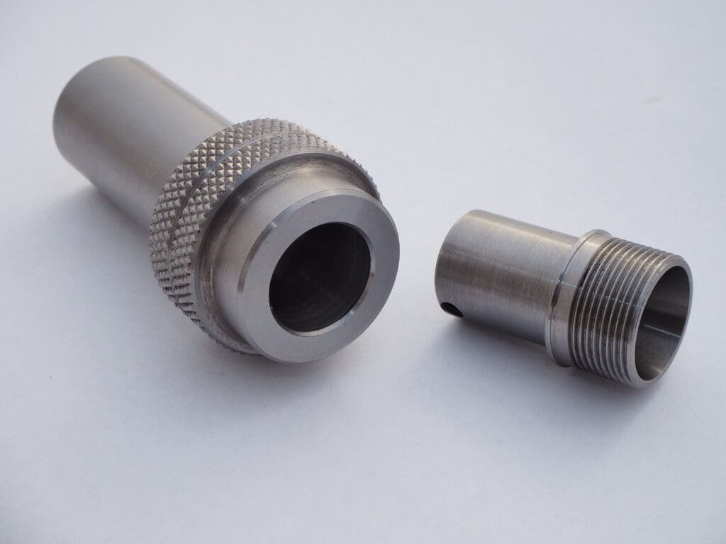
Tailstock Tap Holder – Brett Meacle
This entry is only a simple accessory to make, the whole job could be completed in one piece with only the Collets and Closing nut purchased to finish the job. As outlined in the original article “Sliding Tailstock Holder” MEW 288, I wanted to demonstrate that even without screw cutting facilities, or a lacking of experience or confidence to machine the threads or bore accurate tapers, the job can still be done by a newcomer until they have gained the skills to move onto more complex operations with confidence. All that is required is the production of a few accurate holes by reaming or boring to size, determining the actual size of the hole using plug gauges then machining a matching shaft to fit with a suitable clearance or interference tolerance.
Purchased Items include the ER Collets and Closing Nut, ER Motor shaft chuck to modify and a Modified 2MT Arbor.
A number of years ago I made GHT’s Threading tools, the sliding die holder was made, the ease and convenience of having preset dies proved well worth the time & effort.
Interest dwindled before I moved onto the sliding tap holder and I continued to use the time honored method of holding the tap in the tailstock and sliding it along the bed, winding the chuck with a mandrel handle. This works well with larger taps but you lose some feel with small ones, which can lead to oversized threads.
The original drawings showed the taps being held in a series of adaptors drilled to match the shanks of different size taps and secured with grub screws. The only drawback is that taps seem to come in a large variety of shank sizes and to complete the tapping attachment would require a similar number of different sized bushes.
I came across a series of ERG 16 tapping collets, which not only hold the shank of the tap but also the square section. They are a bit of overkill for the task, and I’m sure normal ER collets would hold the taps securely. I was able to use the smaller ERM style closing nut for a more compact, neater looking arrangement.
Deciding on the ER16 size, the tap holder was enlarged slightly and a tommy bar hole was drilled into the knurled section. This hole with a tommy bar inserted allows holding the tap holder when tightening the collet, also gives something to grip when tapping larger sizes, as holding the knurled surface will become uncomfortable after a certain point.
To machine the shank of the collet holder, a collet was clamped onto a turned spigot held in the lathe chuck. The two parts were assembled using a shrink fit but could also be completed using one of the widely available liquid adhesives.
The completed sliding tap holder has improved the quality and fit of small threads and could also double as a sensitive drilling attachment for small drills.
Vote using the link here COMPETITION VOTE.
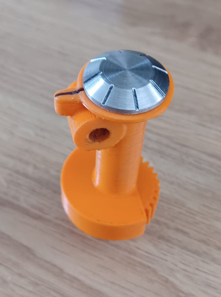
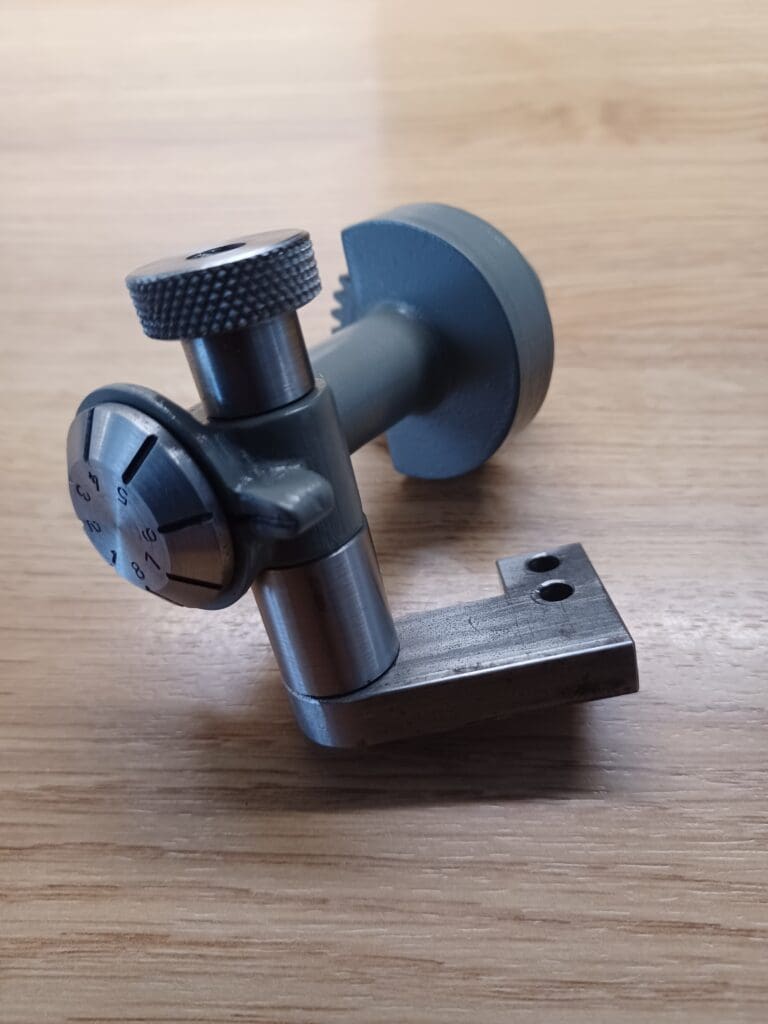
Myford Screw Cutting Indicator – David George
I had been looking at making a screw cutting indicator the same as the one on my lathe, as a new original seemed a bit pricy. I drew up the parts in Alibre Atom 3D and looked at casting the body, but a friend said he could 3D print it and it could be used as a pattern. After printing other than a couple of areas where the cross-support diameter contacts the main body which needed filling, it seemed perfect to use as is. There is also a gear which was supposed to be used on a Boxford would be suitable to match the leadscrew on my lathe. The only difference is it is twice the size, so I had to modify the bottom part of the body model to suit the larger gear. The gear has a recess to take a bush to allow for a grub screw to hold the gear to the shaft when tapped and I decided to make the top indicator with shaft from steel, but it could be made by printing as well. For my use I have made a shaft, bracket and knurled nut to support the indicator from steel but again these are available for printing. The gear has a grub screw in the lower boss, and I decided to fit a bush into the gear to make the thread more substantial so that it is possible to set the indicator line prior to use. The plastic used to print the body and gear was a bit orange and I decided to paint it to match my lathe and it now looks just the part. After assembling it worked well and after painting just the ticket and a bit cheaper.
Vote using the link here COMPETITION VOTE.
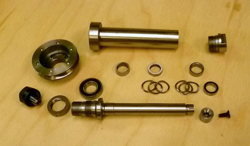
Taylor Hobson Engraver Spindle – John Cuckson
Unlike most of my projects, this was not so much a matter of choice but of necessity. I bought a Taylor Hobson D Engraving Machine at auction but shortly after I began using it, I realised it was noisier than it should be and, more importantly, it gave a terrible finish both when engraving and when light milling. It was clear the spindle was at fault and after some trouble dismantling it, I found out why. The original design is very elegant relying on hardened, uncaged balls running directly on the very hard spindle which developed spalling followed by false brinelling. At some stage I will endeavour to regrind the spindle (it seems to be through-hardened) as well as the outer races which were similarly damaged. But to get the machine up and running, I decided to make a completely new spindle and to fit the nose with E11 collets rather than the proprietary taper fitting that Taylor Hobson used. The E11 collet enables standard 1/8-inch diameter cutters to be used plus all the other sizes covered by this range of collets.
The new spindle design is based on thin section ball bearing races with a 24mm X 12 mm X 6mm race at the nose (which carries the pulley and takes most of the cutting forces) and a 15mm X 10mm X 4mm race at the top. Preload is provided by two stacks of three wavy washers each 0.3 mm thick pushing via a sleeve on to the outer race of the upper bearing. The spindle was made of unhardened 080M40 (ex EN8). Getting the right size wavy washers proved impossible so their outer and inner diameters had to be adjusted to fit the space in the barrel while keeping the spindle diameter as large as possible. The resulting spring rate then had to be recalibrated and spacer thicknesses adjusted to achieve the desired preload of 50 Newtons having carefully measured all the relevant shoulder lengths. The drive from the pulley to the spindle copied the original where a flat key on the inside of the pulley drives a flat on the spindle.
The design challenge was to come up with a design that allowed all the pieces to match precisely the outer diameter and length of the original Taylor Hobson spindle. Plus, of course, the pulley had to match the original to maintain the machine’s speed range of up to 18,000 rpm. An additional feature was a ring of pin holes in the upper part of the pulley to enable a small specially made pin spanner to hold the spindle while the collet is tightened and loosened.
Vote using the link here COMPETITION VOTE.