
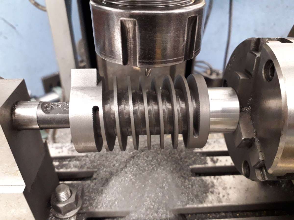
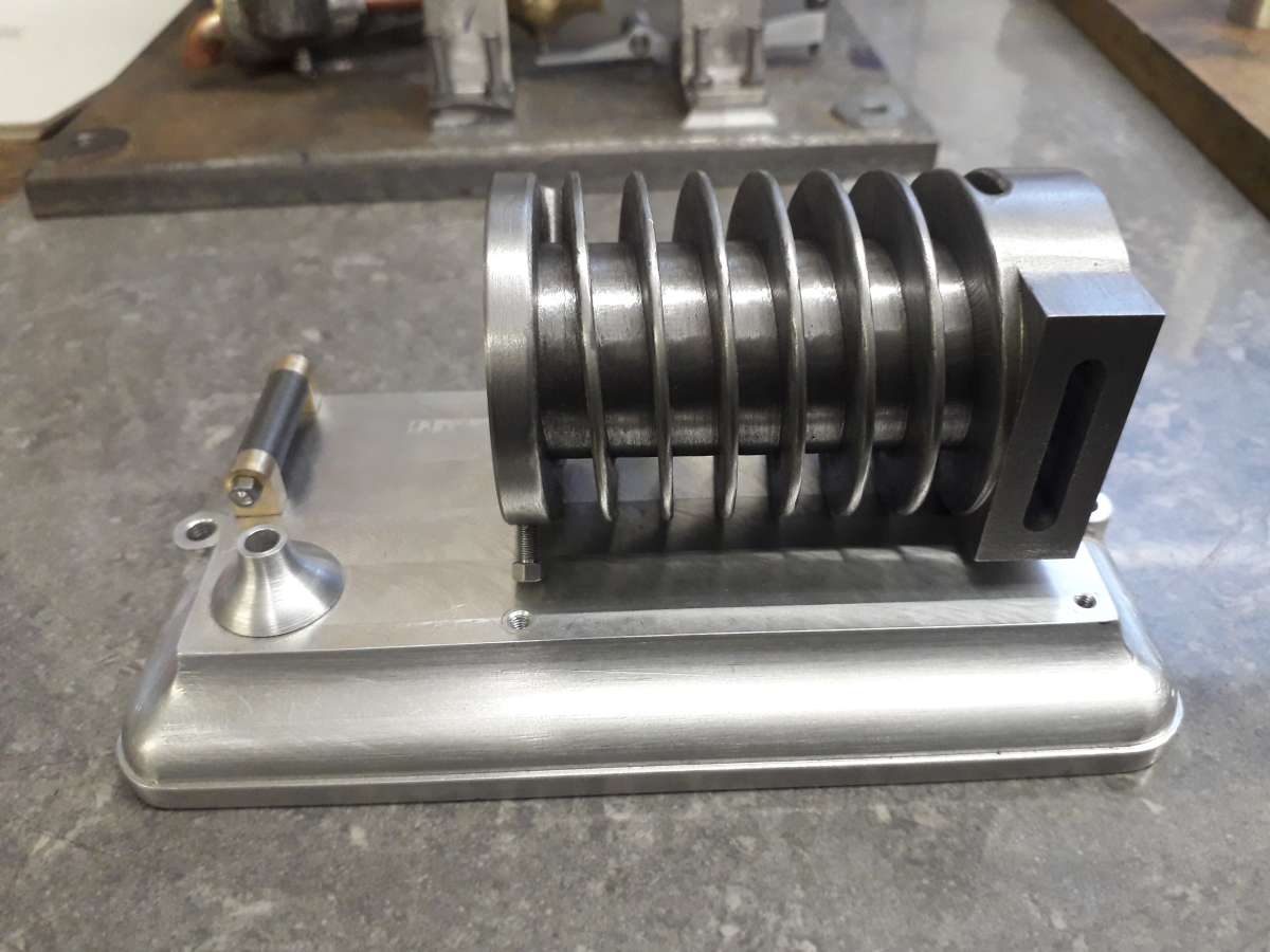
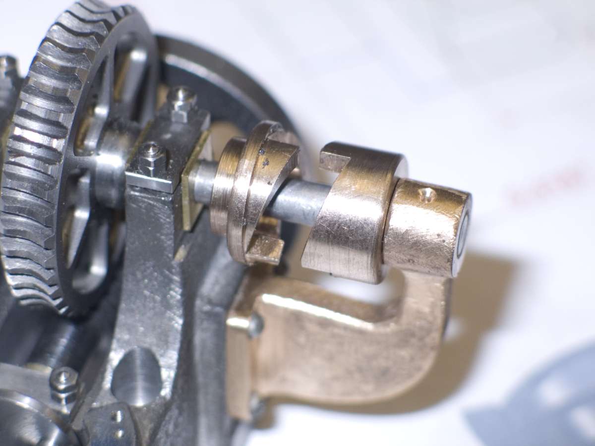
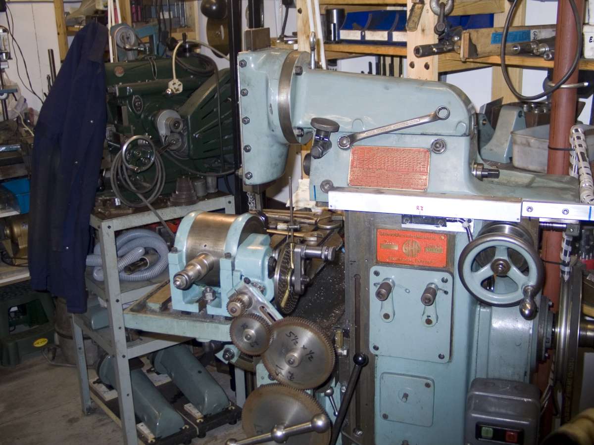
Creating a spiral
Creating a spiral
- This topic has 13 replies, 10 voices, and was last updated 5 August 2024 at 07:33 by
 JasonB.

- Please log in to reply to this topic. Registering is free and easy using the links on the menu at the top of this page.
Latest Replies
-
- Topic
- Voices
- Last Post
-
-
Warco 720
1
2
Started by:
Mick Bailey
in: Manual machine tools
- 12
-
23 December 2024 at 08:03
Diogenes
-
Stuart Steam Boiler Feed Pump – Cylinder Scrapped
Started by:
David Deaville
in: General Questions
- 4
-
23 December 2024 at 07:59
David Deaville
-
How would you do this?
Started by:
moonman
in: Beginners questions
- 5
-
23 December 2024 at 07:29
Diogenes
-
Warco WM290V and ELS
Started by:
Steven Shand
in: CNC machines, Home builds, Conversions, ELS, automation, software, etc tools
- 6
-
23 December 2024 at 06:51
thisdesignedthat
-
Forum Post downloads to user
Started by:
Speedy Builder5
in: Website Questions, Comments, and Suggestions
- 1
-
23 December 2024 at 06:12
Speedy Builder5
-
Help for DIY lathe build.
Started by:
moogie
in: Help and Assistance! (Offered or Wanted)
- 9
-
22 December 2024 at 23:45
not done it yet
-
Discussion on the Future Direction of Model Engineer and Workshop
1
2
3
4
Started by:
Neil Wyatt
in: Model Engineer.
- 45
-
22 December 2024 at 23:32
IanT
-
How to sort this problem out.
Started by:
Michael Callaghan
in: Workshop Techniques
- 9
-
22 December 2024 at 23:11
Mick Bailey
-
Drill press will not start
Started by:
AStroud
in: Help and Assistance! (Offered or Wanted)
- 7
-
22 December 2024 at 22:16
Charles Lamont
-
New member from belgium
Started by:
davp1971
in: Introduce Yourself – New members start here!
- 1
-
22 December 2024 at 21:38
davp1971
-
ELS for BOXFORD AUD
1
2
3
Started by:
Speedy Builder5
in: Workshop Tools and Tooling
- 17
-
22 December 2024 at 19:40
Robert Atkinson 2
-
Recommissioning a small vertical boiler
Started by:
Mark Salzedo 1
in: General Questions
- 7
-
22 December 2024 at 19:24
Mark Salzedo 1
-
Replacement Motor Wiring
Started by:
Gary Lynch
in: General Questions
- 3
-
22 December 2024 at 19:06
noel shelley
-
Dial gauge troubles
Started by:
Roger Hart
in: Workshop Tools and Tooling
- 9
-
22 December 2024 at 14:35
Mick B1
-
L5 issue
Started by:
Neil Taylor
in: Beginners questions
- 6
-
22 December 2024 at 10:43
Emgee
-
Drilling holes in boiler banding.
Started by:
Michael Callaghan
in: Hints And Tips for model engineers
- 8
-
22 December 2024 at 07:03
JasonB
-
Model Engineering Survey – What Do YOU make?
1
2
3
4
Started by:
SillyOldDuffer
in: General Questions
- 52
-
21 December 2024 at 23:01
SillyOldDuffer
-
Microscope marking objective
Started by:
old mart
in: Clocks and Scientific Instruments
- 6
-
21 December 2024 at 20:48
old mart
-
new life for old chuck
Started by:
old mart
in: Workshop Tools and Tooling
- 1
-
21 December 2024 at 20:18
old mart
-
Some VERY interesting LED modules
1
2
…
5
6
Started by:
Michael Gilligan
in: Electronics in the Workshop
- 18
-
21 December 2024 at 19:23
SillyOldDuffer
-
775 Motor based Dynamo ?
1
2
Started by:
JasonB
in: Miscellaneous models
- 6
-
21 December 2024 at 18:48
JasonB
-
Sable 2015 Desktop CNC / engraver
Started by:
Bazyle
in: CNC machines, Home builds, Conversions, ELS, automation, software, etc tools
- 9
-
21 December 2024 at 17:54
John Haine
-
GRIPTRU Chuck adjust
Started by:
Speedy Builder5
in: Workshop Techniques
- 12
-
21 December 2024 at 14:31
Michael Gilligan
-
What did you do Today 2024
1
2
…
20
21
Started by:
JasonB
in: The Tea Room
- 75
-
21 December 2024 at 14:30
bernard towers
-
Miniatur Wunderland
Started by:
Paul Lousick
in: Miscellaneous models
- 3
-
21 December 2024 at 11:30
noel shelley
-
Warco 720
1
2
Latest Issues
Newsletter Sign-up
Latest Replies
- Warco 720
- Stuart Steam Boiler Feed Pump – Cylinder Scrapped
- How would you do this?
- Warco WM290V and ELS
- Forum Post downloads to user
- Help for DIY lathe build.
- Discussion on the Future Direction of Model Engineer and Workshop
- How to sort this problem out.
- Drill press will not start
- New member from belgium

