In the previous part of this article I showed how a change in approach from the traditional to one of using shallow but fast cuts can improve how face/shell mills perform on hobby size machines. This time I will show how a change of insert can further improve finish, speed up the machining time and also put less load onto a lighter machine.
Insert Types.
Although there are many styles of insert for the vast array of holders on the market they can generally be divided into two main types: Those that are designed for cutting ferrous metals such as steel and iron and those designed to cut Aluminium and other non ferrous metals. The ones for ferrous tend to have a blunter cutting edge as they are moulded from powder and then just coated and can usually be distinguished by having a gold/bronze colour but also can be grey. Depending on their exact intended material use some can be “blunter” than others. The inserts for non ferrous on the other hand are much sharper which is often a result of grinding, polishing or lapping after the initial shape has been moulded and they tend to have a bright polished appearance.
The codes used to distinguish these two main types of insert are not as clear cut as they are for lathe turning inserts so you may find the third letter in the code does not always signify what purpose they are intended for. Some manufacturers tend to suffix the shape/size code with one that relates to the intended material such as HO1 for the polished inserts for aluminium.
It is the sharpness of these non ferrous inserts that can be taken advantage of on a lighter constructed and less powerful hobby machine as for the same given size of cut they do not load the machine as much as the ferrous inserts do. This not only puts less strain on the motor and drive train but as the cutter is less likely to be forced off the surface as the machine flexes the resulting cut is likely to be more accurate and have a better finish.
This sharpness also makes it possible to increase the chip load and therfore feed rate when using these cutters and still not load the machine as much as it would taking a similar depth but slower feed with non ferrous inserts. As an example although I was able to cut at 450mm/min feed with the ferrous inserts I could hear the machine was being loaded quite a lot so a feed of 300mm/min would be about as fast as I would want to go for general use. However the machine sounded far happier cutting at 450mm/feed with the non ferrous inserts.
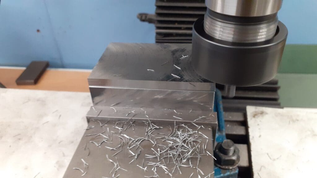
Photo 11 is a close up of the finish from the general purpose APMT inserts and although it has quite a bright reflective look when you examine it closely there is some tearing of the surface and the back edge of the cutter left a more pronounced mark which suggests the machine was flexing with the load of the leading edge cut.
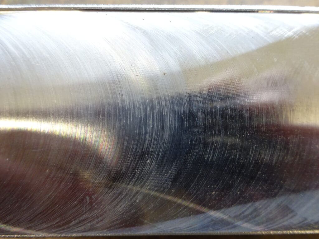
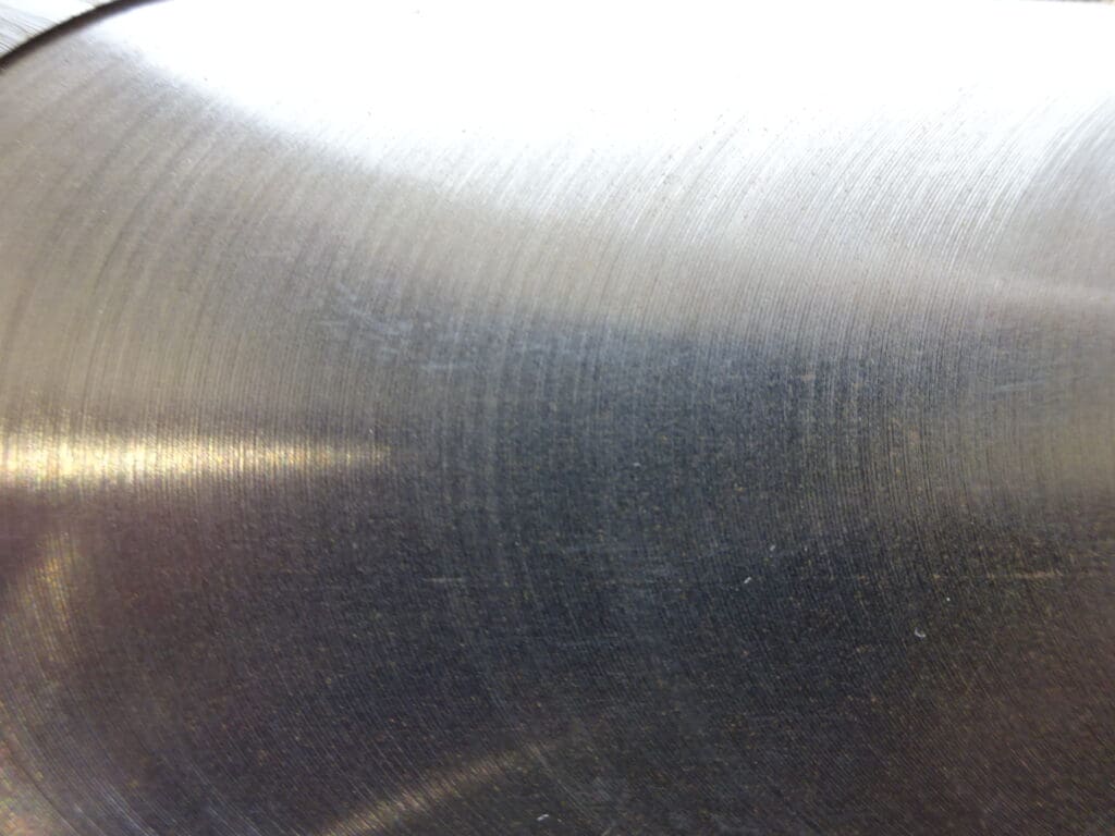
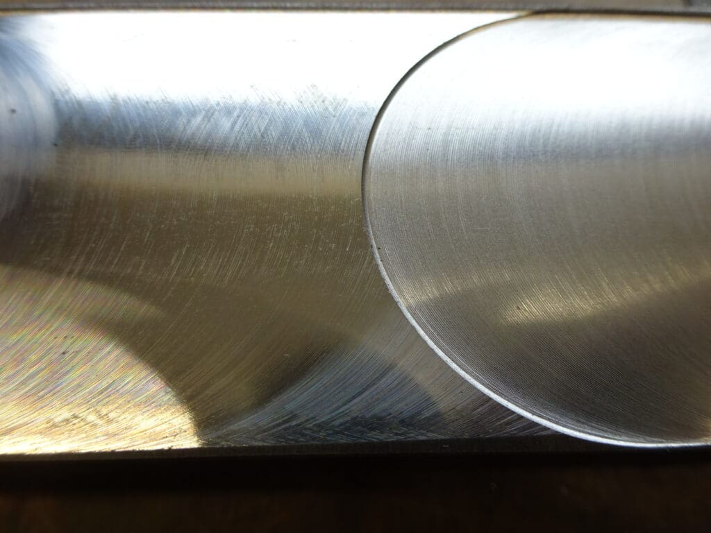
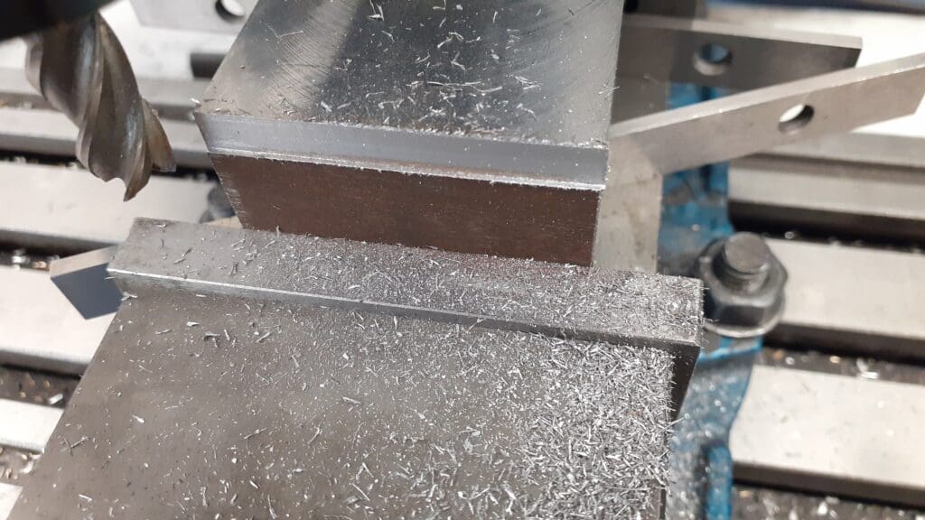
Photo 12 is a close up of the finish from the polished APKT non ferrous inserts which is far more uniform with no signs of the surface being torn as the sharper cutting edge cuts rather than pushes the material out of the way. There is also very little sign that the back edge was cutting suggesting less load is being created that may flex the cutter away from the work. Photo 13 shows the two surfaces back to back.
Enjoy more Model Engineer reading in the monthly magazine.
Click here to subscribe & save.
The final photo related to the insert face/shell milling cutters Photo 14 gives an idea of the type of finish the non ferrous APKT inserts will give on a range of materials commonly used in the home workshop. All samples are approx 50mm wide and were cut using a 5 insert 50mm dia cutter running at 2000rpm, feed rate of 450mm/min and a depth of cut of 0.5mm. All were cut dry with the exception of the aluminium which had a small amount of paraffin brushed onto the surface which helps prevent a build up of material on the tip of the insert.
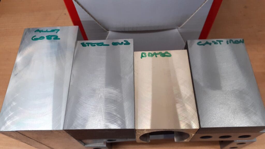
From Left to right the samples are 6082-T6 aluminium. 070M20 (EN3) steel. CZ121 Brass and GR17 cast iron. The following link will take you to a Youtube video of these pieces being cut and should better show the finish obtained.
In summary the figures below can be taken as a starting point when using insert face and shell mill cutters on a bench top hobby machine, they can be further tweaked depending on the actual machine and type/size of cut. See the previous part of this article on how to work out the rpm and feed rate for a specific cutter using the parameters below.
Steel & Iron with APMT or other moulded type inserts 200-250 m/min cutting speed and a chip load of 0.02mm to 0.03mm per insert. Depth of cut 0.5mm.
Steel & Iron with APKT or other polished non ferrous insert 225-275m/min cutting speed and a chip load of 0.025mm to 0.035mm per insert. Depth of cut 0.5mm.
Aluminium and other non ferrous metals with APKT or other polished non ferrous insert 300-350m/min cutting speed and a chip load of 0.04-0.05mm per insert. Cutting depth of 0.5mm.
Solid milling cutters
In much the same way as face mills the traditional approach with “slot drills” and “end mills” was to run fairly slowly and remove a reasonable amount of material per pass which was fine on a heavy full size machine but is not always the best option with the smaller bench top machines. For these a look at how CNC machining methods make use of lighter cuts but with the tool running faster can get the job done in the same or even less time.
The faster running is often due to using solid carbide cutters which have a much faster cutting speed – typically 3 times that of HSS and that is an option for home use as the difference in cost between the two materials certainly in the smaller diameters is not that great. However even sticking with HSS if the diameters are kept small then the hobby mill can still be run at or around it’s maximum spindle speed without over speeding the cutting tool.
HSS Cutters
The old rule of thumb was to use ¼ the cutters diameter per pass (sideways) but reducing this to 1/10 cutter diameter or 0.1D reduces the load when using the side of the cutter and that can be combined with using a vertical depth of 1 times the cutter diameter or 1D
If we take cutting steel as a starting point then a 6mm diameter coated HSS tool can be run at a speed of up to 2500rpm, not all hobby machines will run at those speeds so using 2000rpm as an example and the same formulas that were used for the face mills then feed rates can be worked out as follows.
For a side cut of 6mm vertical depth and 0.6mm horizontal depth a good starting chip load would be 0.035mm which will give a good finish and not overload the machine. So the feed rate is 0.035 x 2000 = 70mm per flute. Therefore depending on what cutter you are using, a 3flute cutter can be fed at 210mm/min or a 4-flute at 280mm/min.
Photo 15 shows a piece of steel that has had a 6mm x 0.6mm cut taken at a feed rate of 200mm using a 3 flute coated HSS cutter that gave a good finish, minimal burrs to the edges and clean good size chips, the cut was done dry.

The following video shows cuts being made in steel both slower and faster than these figures which illustrates there is some flexibility and why I have said to take them as a starting point and adjust to suit your particular machine.
I have also included a couple of cuts with a 10mm dia 3-flute cutter firstly using the same 10mm x 1mm (1D x 0.1D) with a reduced feed rate of 120mm/min (0.02mm chip load) and then a shallower cut of 10mm x 0.5mm (1D x 0.5D) feed at 180mm/min (0.03mm chip load) somewhere between the two will be a good compromise between getting the job done, good finish and not straining the machine.
Lastly some cuts in other materials, all cutting parameters are given in the video’s on screen captions. For Aluminium and other non ferrous metals it is better to use an uncoated cutter to reduce the risk of the aluminium sticking and building up on the cutting edge. The sideways depth of cut can be increased with these materials from the 10% used on steel to around 15-20%, so typically 1mm sideways for our 6mm dia cutter. Due to the faster removal rates on the non ferrous metals it is also a good idea to purchase the ones designed specifically for them which have a higher helix angle that removes the large amount of swarf that is generated better than the standard helix angled cutters do.
For a slot the chip load is best reduced slightly so start with 0.025mm, cut width will be the full 6mm diameter of the cutter and vertical depth per pass of around 0.15D. So the feed rate will be 0.025 x 2000 = 50mm per flute. Note 4-flute cutters are not really suited to cutting slots as they can cut oversize if the cutter deflects. This reduced number of flutes will need to be taken into account therefore a 2-flute cutter can be fed at 100mm/min or a 3-flute cutter feed at 150mm/min.
The vertical height should not be too low as that will simply wear the very corners of the flutes and quickly blunt them which becomes costly, aim for at least 1mm depth which won’t unduly load the mill or risk chatter. Only reducing this for very small diameter cutters that are not as strong.
Non Ferrous metals can have both a higher chip load and the cutter run faster, a starting point for a 2 Flute 6mm Aluminium specific cutter would be 20-25% of its diameter as the depth and a chip load of 0.04mm to 0.06mm per flute. The following video shows some slots being cut in various metals
Solid Carbide cutters
Although probably not the best choice to start learning on as they are a bit more delicate and can easily be damaged by mishandling solid carbide cutters do have some advantages over HSS. Firstly they can be run faster, typically 3 times as fast which will mean that if you have a need for a larger diameter cutter the mill can still be run within its higher speed ranges to get the most out of it. Also if you have a machine that has a higher top spindle speed than the usual 2-2.5K rpm such as a SX3.5 then full use can be made of it’s 5000rpm top speed.
A carbide cutter is also less flexible than one of the same size made from HSS so longer side cuts can be made which is good if you want to do full depth profile cuts to get a better finish than a series of step downs may produce. If you don’t have a machine that can take advantage of their higher speed then increasing the depth of cut that their stiffness allows will reduce cutting times.
Lastly they are harder wearing so although the initial purchase price may be a bit higher if looked after that can more than be made up for by the greater amount of cutting they can do before becoming blunt. Their hardness is also useful on some of the more difficult to cut materials such as chilled iron castings that may take the edge straight of a HSS cutter but the Carbide will manage to cut it.
A cutter is not for life
Cutters will get blunt and when they do it is best to replace or possibly sharpen them rather than carry on using one that is past it’s best. Not only will a blunt cutter put more load on the machine it will give a poorer finish . Two tell tail signs that a cutter has started to loose it’s edge are larger burrs along the edges of the cut and the swarf coming off as crumbs or dust. If you look at the videos you will see the swarf is all coming off in large chips and there is very little in the way of burrs. Compare Photos 16 & 17 where 16 has been cut with a sharp cutter and 17 shows the results of using a blunt one.
https://www.arceurotrade.co.uk/Catalogue/Machines-Accessories/Milling-Machines/SIEG-SX27-Mill
https://www.arceurotrade.co.uk/Catalogue/Cutting-Tools/Indexable-Carbide-Shell-Mills