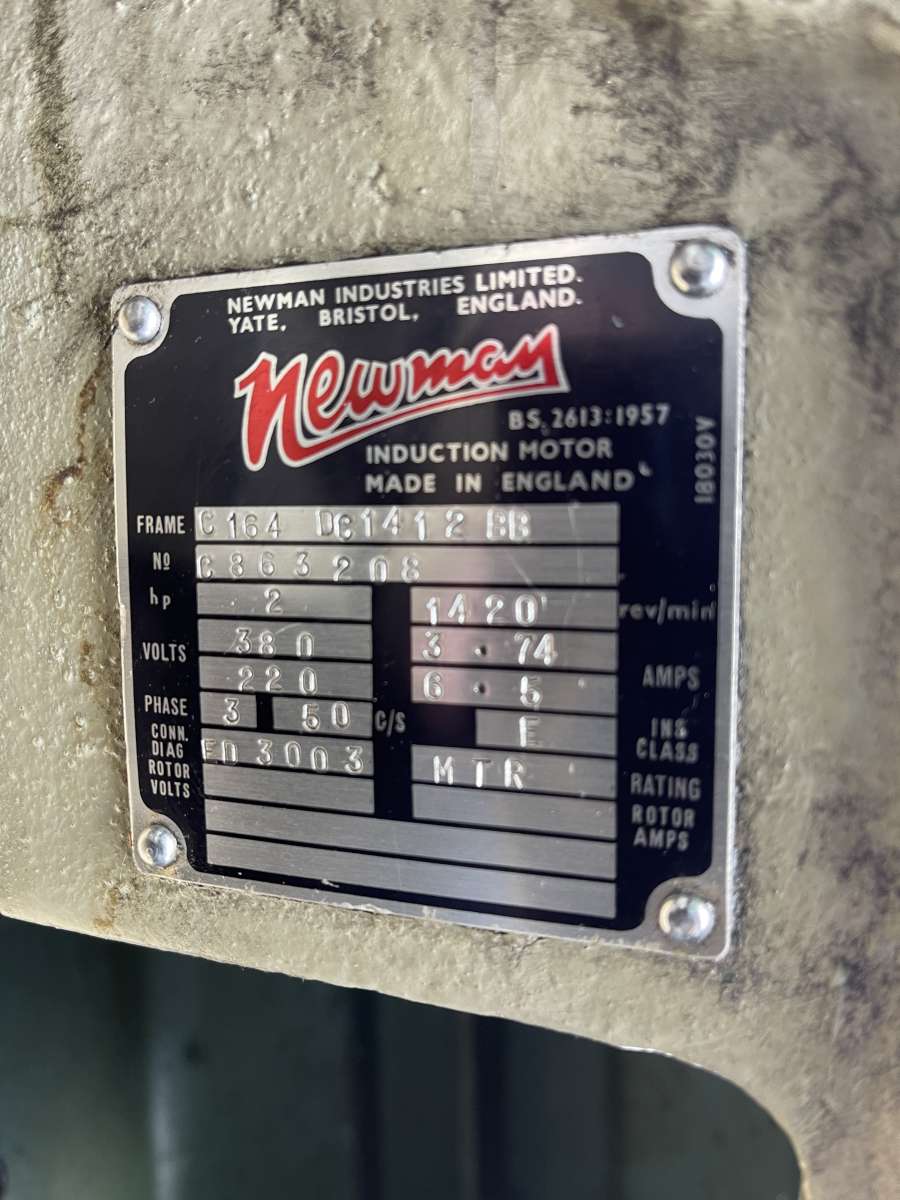
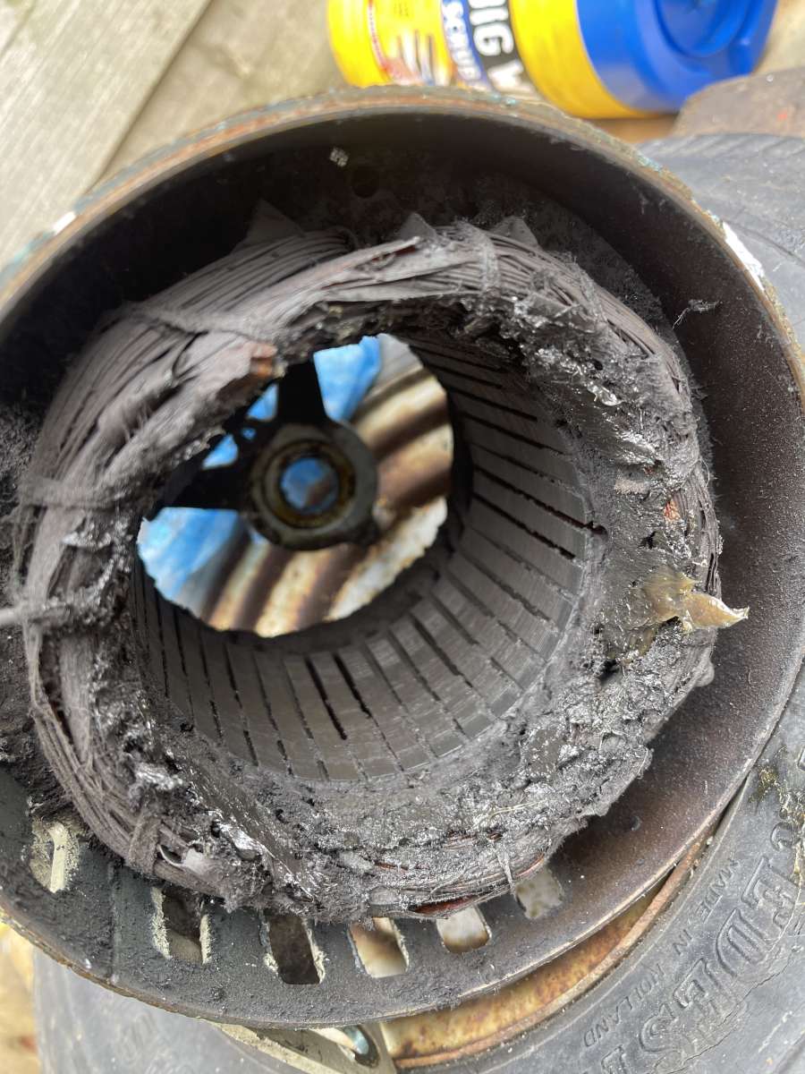
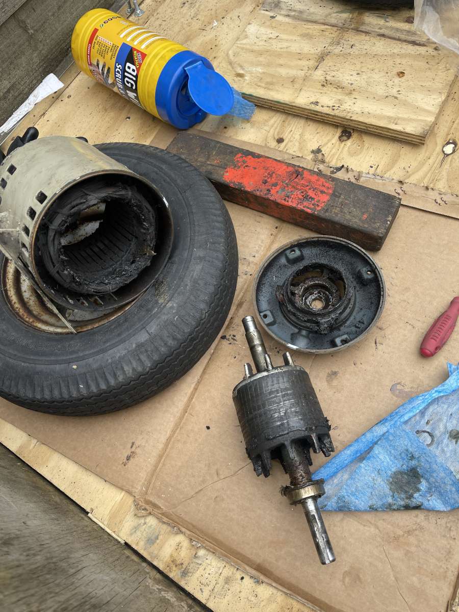
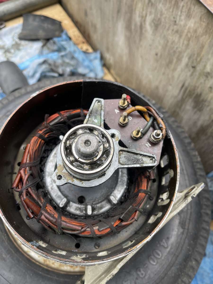
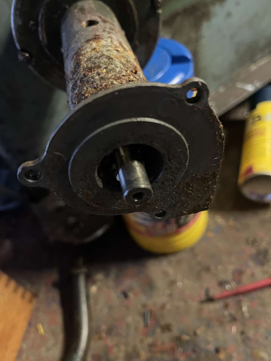
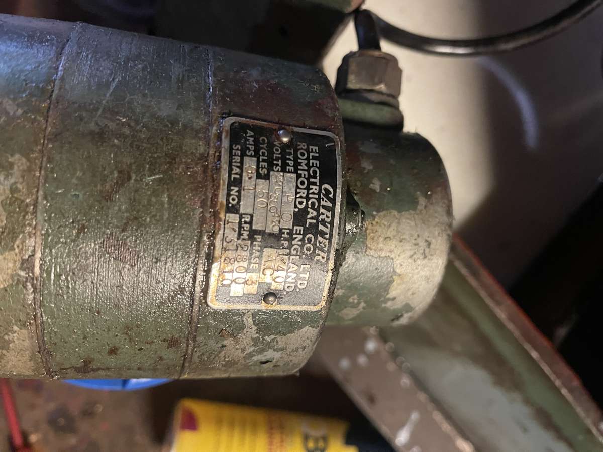
Motorun 2HP statin 3phase converter
Motorun 2HP statin 3phase converter
- This topic has 24 replies, 5 voices, and was last updated 28 June 2024 at 21:20 by
 45chop.
 Hi there,

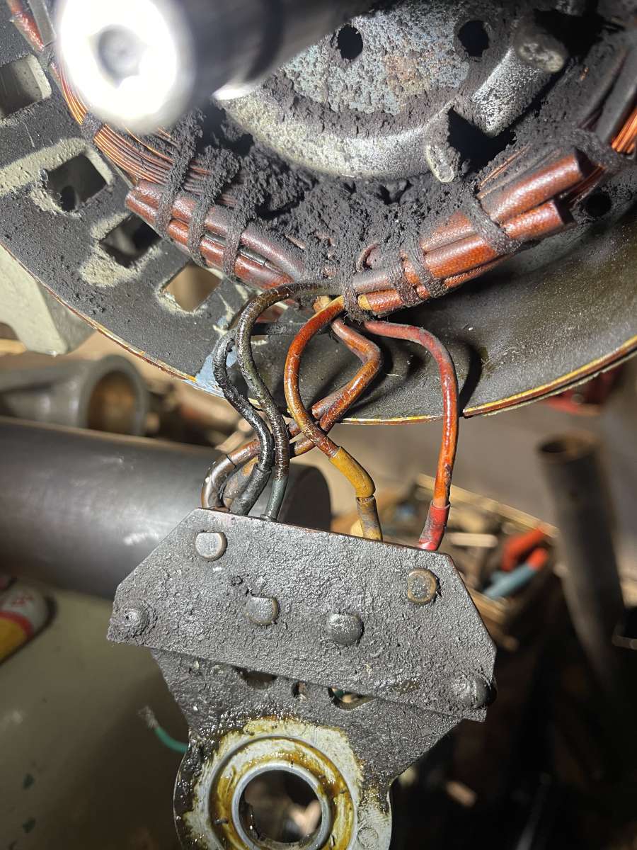
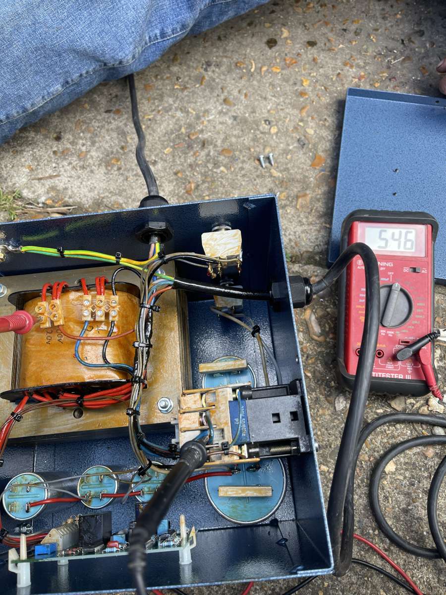
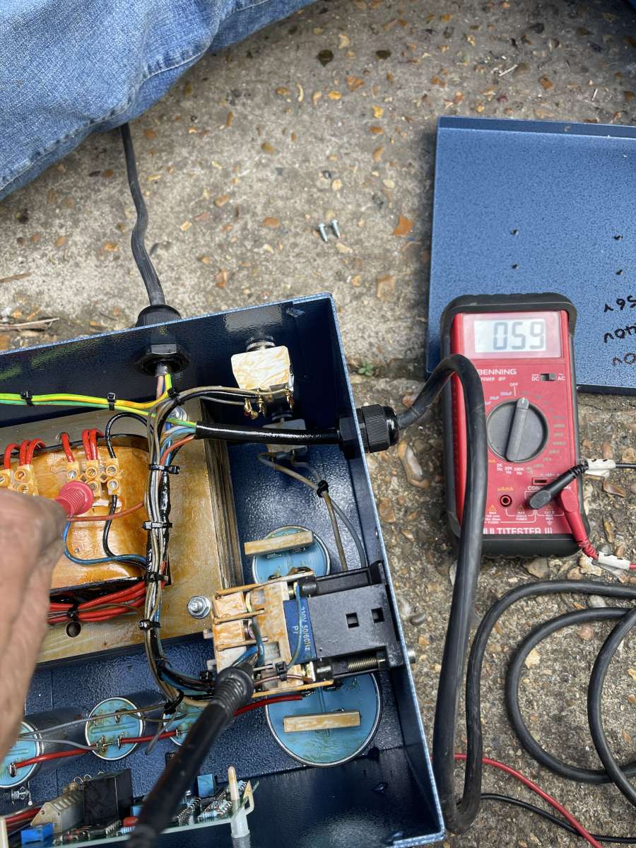
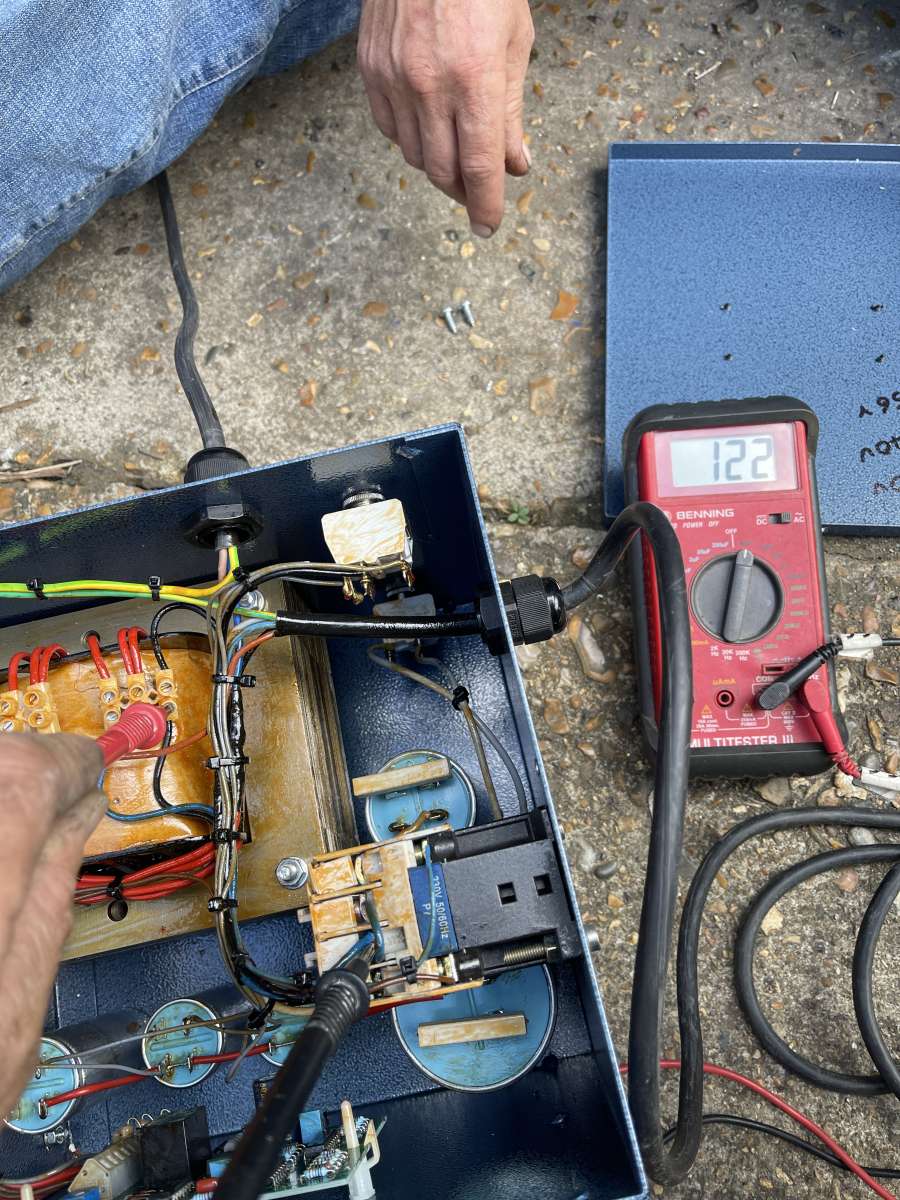
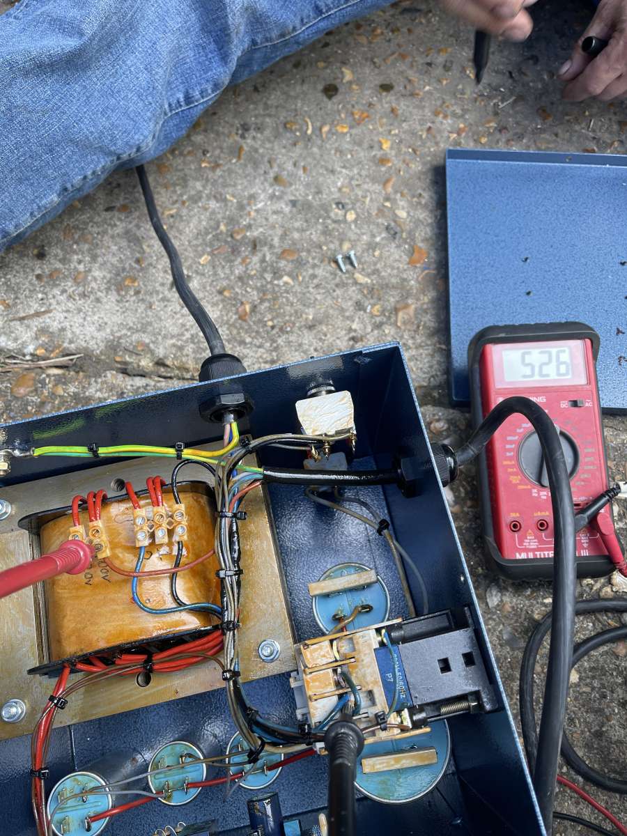
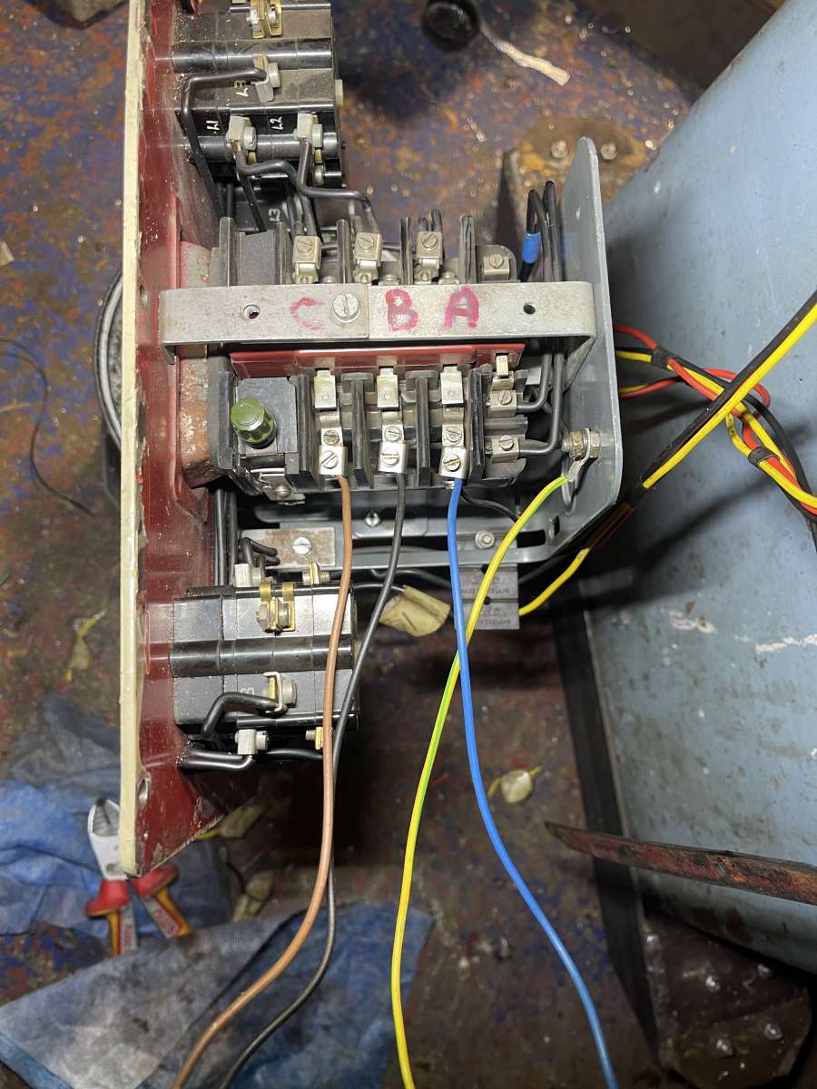
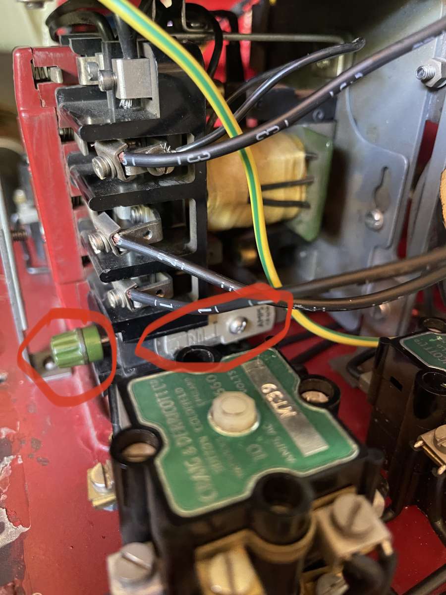
 Update, not quite there, powered up that I know of, as in the inverter clunks and hums but pushing the contact switch on the control panel doesn’t hold down
- Please log in to reply to this topic. Registering is free and easy using the links on the menu at the top of this page.
Latest Replies
-
- Topic
- Voices
- Last Post
-
-
Lidl castors
Started by:
Michael Gilligan
in: The Tea Room
- 5
-
21 July 2025 at 07:30
larry phelan 1
-
Redwing Cylinder head
Started by:
Durhambuilder
in: I/C Engines
- 3
-
21 July 2025 at 07:24
David George 1
-
Model Engine running just off a naked flame
Started by:
Blue Heeler
in: Stationary engines
- 6
-
21 July 2025 at 07:17
JasonB
-
Hopeless…Alibre Ass
Started by:
Nigel Graham 2
in: CAD – Technical drawing & design
- 4
-
21 July 2025 at 06:56
JasonB
-
My vise isn’t at 90 degrees
Started by:
moonman
in: Beginners questions
- 14
-
21 July 2025 at 01:19
Kiwi Bloke
-
Hofmann Rollers
Started by:
Martin Kyte
in: General Questions
- 7
-
21 July 2025 at 00:30
gerry madden
-
What Did You Do Today 2025
1
2
…
8
9
Started by:
JasonB
in: The Tea Room
- 33
-
20 July 2025 at 21:39
Dalboy
-
Polishing compounds for stainless steel (mild abrasives))
Started by:
Simon Williams 3
in: Beginners questions
- 13
-
20 July 2025 at 20:02
Russell Eberhardt
-
Bad design, or am I missing something?
Started by:
half whit
in: Beginners questions
- 5
-
20 July 2025 at 19:16
Julie Ann
-
Mistry dividing attachment
1
2
Started by:
Brian Merrifield
in: Workshop Tools and Tooling
- 17
-
20 July 2025 at 18:43
Tony Jeffree
-
Epoxy or acid etch primer
Started by:
Michael Callaghan
in: Materials
- 1
-
20 July 2025 at 16:46
Michael Callaghan
-
Diving in to ATC?
Started by:
Steve355
in: CNC machines, Home builds, Conversions, ELS, automation, software, etc tools
- 4
-
20 July 2025 at 16:20
Martin Connelly
-
Measuring a double Vee lathe bed Vee position
Started by:
Kim Garnett
in: General Questions
- 11
-
20 July 2025 at 15:51
Kim Garnett
-
Please direct me to where I can find an engineer to do some bespoke work
Started by:
srb1
in: Beginners questions
- 6
-
20 July 2025 at 15:43
Craig Brown
-
Making Unimat DB/SL Steadies
Started by:
Andy Carlson
in: Workshop Techniques
- 3
-
20 July 2025 at 15:35
Andy Carlson
-
Alternative to ARC
Started by:
petro1head
in: General Questions
- 4
-
20 July 2025 at 13:31
JasonB
-
Sat nag
1
2
Started by:
duncan webster 1
in: The Tea Room
- 24
-
20 July 2025 at 13:18
Nigel Graham 2
-
Which lubricator do I need
Started by:
Michael Callaghan
in: Locomotives
- 3
-
20 July 2025 at 12:45
Michael Callaghan
-
Advice to machine stationary engine base plate
Started by:
Greg H
in: General Questions
- 5
-
20 July 2025 at 11:37
Greg H
-
Paint stripper does not do what it says on the tin
Started by:
Greensands
in: Hints And Tips for model engineers
- 8
-
20 July 2025 at 11:11
Taf_Pembs
-
Easiest/cheapest source of R8 socket
1
2
Started by:
Beardy Mike
in: Workshop Tools and Tooling
- 14
-
20 July 2025 at 11:01
Tony Pratt 1
-
Hofmann
Started by:
Matt Smith
in: General Questions
- 2
-
20 July 2025 at 10:37
Tony Pratt 1
-
Even the Dealer Didn’t Know!
Started by:
Chris Crew
in: The Tea Room
- 15
-
20 July 2025 at 07:54
Nealeb
-
Boxford paint colour
Started by:
Pete.
in: Workshop Tools and Tooling
- 5
-
20 July 2025 at 01:21
Pete.
-
More BBC Masterchef woes…
Started by:
Nigel Bennett
in: The Tea Room
- 6
-
19 July 2025 at 22:55
Nigel Graham 2
-
Lidl castors
Latest Issue

Newsletter Sign-up
Latest Replies

