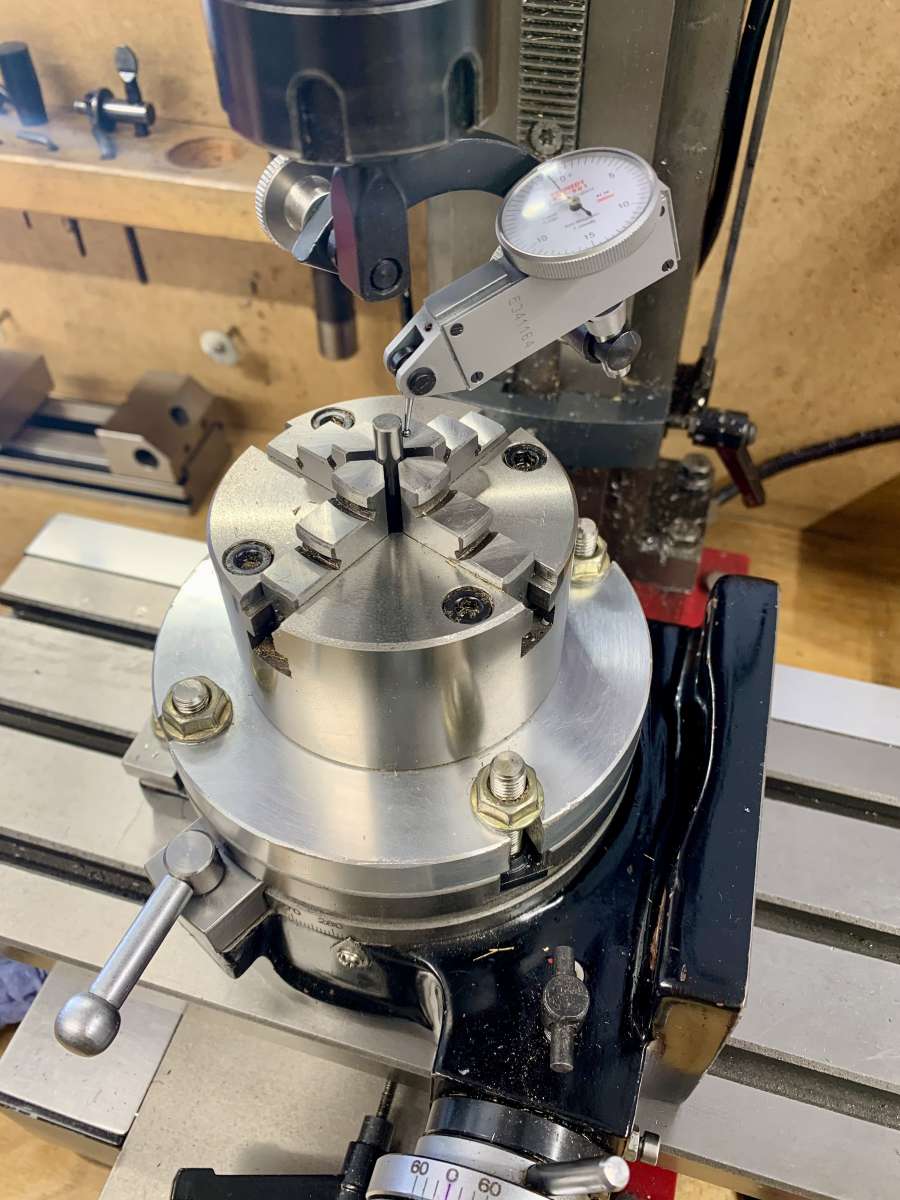
Centering R/T chuck

Advert

Centering R/T chuck

Home Forums Workshop Techniques Centering R/T chuck

Viewing 25 posts - 1 through 25 (of 39 total)
  • Author
    Posts
  • #734868
    Dr_GMJN
    Participant
      @dr_gmjn

      All, what’s the best way of centering this R/T chuck under the mill spindle please?

      I’ve centred the R/T itself fairly easily using the dti into the central taper, rotating the spindle and adjusting the x/y table until I get a zero reading all the way around.

      In the past I’ve resorted to clamping a chamfering tool or something in the chuck, clamping the protruding stub into a spindle collet, and tightening the chuck-R/T bolts. I can get within 0.004” like this, but no better.

      If I use the dti rotated in the spindle, I can only adjust the chuck by tapping it in x/y in turn with a soft hammer, but unlike using the x/y table, tapping x invariable screws up y.

      Also, is there a good way of keying or dowelling the chuck to the R/T table such that I don’t have to do this setup again? It always takes ages, and is never that great in terms of accuracy.

      Any advice welcome!

      IMG_7189


      Advert
      #734879
      Anonymous

        In more than 20 years I’ve never needed to use a chuck on a rotary table. Much simpler to use a spigot, or similar, in the centre hole for locating the work. On my rotary table that is possibly easier as the centre hole is 1″ diameter parallel rather than tapered.

        Andrew

        #734880
        Clive Foster
        Participant
          @clivefoster55965

          I’m unconvinced by your chuck mounting arrangements which don’t seem robust when taking out minor mis-alignments.

          Were I doing the job I’d fit a spigot on the mounting plate so it locates accurately in the centre hole of the rotary table.

          Do the rest of the mount plate machining in situ on the mill with the nascent plate mounted on the rotary table so nothing disturbs the plate to table concentricity.

          First add holes for the mounting bolts, not slots. Strap across the centre with bolts just outside the mount plate screwing into long keys going into the slots in the rotary table will bold it well enough to fit the first pair of bolt holes. Make the location ring for the chuck and fit the bolt holes. As yours is a four slot table it’s neater to align the slots with the jaws.

          Done carefully things will mount and dismount accurately so the only errors will be due to table set up and those inherent to the chuck.

          I set my rotary tables using a spigot held in a collet whose bottom end is a nice fit in the RT centre hole. Error is routinely a tenth or three TIR.

          Not a fan of four jaw self centring chucks. Especially not affordable ones as the inherent error are likely to be a bit worse than a 3 jaw of equivalent quality. As ever anything better than quite reasonable performance needs significantly deeper pockets than most of us have.

          If you carefully arrange the mounting for a normal independent four jaw the alignment problem basically goes away.

          Clive

          PS I’m pretty much with Andrew on the never needed to fit a chuck to a rotary table camp. I’ve frequently thought it might be cool to have the capability so I could swop jobs from lathe to mill with them still in the chuck, as often advised by Model Engineer writers, but lacking it has never been a show stopper. I do have semi-finished D1-4 plate which has been waiting for couple of decades!

          #734881
          Michael Gilligan
          Participant
            @michaelgilligan61133

            I’m not sure how to say this without it sounding patronising, but please believe me … it’s one of the most important things I learned about using the Rotary Table:

            Never lose sight of the fact that centring the R/T under the spindle is one thing, and using the mounted chuck [or any other fixture] to position the workpiece correctly is a completely separate activity.

            Unless you are intending to produce offsets, the R/T must remain concentric with the machine spindle.

            0.004” is not a good number … so I suspect that you are somehow allowing these adjustments to conflate.

            MichaelG.

            .

            Edit: __ expert comments appeared whilst I was still trying to compose these few words.

            #734882
            Dr_GMJN
            Participant
              @dr_gmjn

              Thanks both. The chuck came with the R/T. It’s been pretty useful for cosmetic stuff, but it always annoys me that I can’t ever get it true.

              The spigot I’m wanting to hold in the chuck is the same diameter as the tool shank I’m using for centering, so I assumed that if I centred on it, the substituted the spigot, it should be ok.

              If I had a taper with a parallel shank on the back, perhaps I could fit it into the R/T, clamp the vice on the straight bit, then tighten the bolts. Then open the chuck and pull the plug out. Then again that’s not dissimilar to centering in the spindle collet I guess.

              TBF I’d expect to still get an error from the chuck so maybe 0.004” is the best it’ll get anyway.

              #734920
              Dr_GMJN
              Participant
                @dr_gmjn
                On Michael Gilligan Said:

                I’m not sure how to say this without it sounding patronising, but please believe me … it’s one of the most important things I learned about using the Rotary Table:

                Never lose sight of the fact that centring the R/T under the spindle is one thing, and using the mounted chuck [or any other fixture] to position the workpiece correctly is a completely separate activity.

                Unless you are intending to produce offsets, the R/T must remain concentric with the machine spindle.

                0.004” is not a good number … so I suspect that you are somehow allowing these adjustments to conflate.

                MichaelG.

                .

                Edit: __ expert comments appeared whilst I was still trying to compose these few words.

                Thanks Michael. As I said, the R/T is centred, and to be clear, I’m not trying to adjust the chuck and R/T simultaneously.

                Im asking how to centre the chuck on the already centred R/T.

                I didn’t design or make the 4 bolt/slot mounting method, it’s what the chuck/R/T came with.

                If the best method involves making some minor mods or setting tools, that’s fine.

                #734921
                MikeK
                Participant
                  @mikek40713

                  If the play for setting true exists in the chuck mounting to the backplate, then I would consider four blocks fitted to the backplate such that you could pass a bolt through each to bear upon the chuck.  If the play exists between the backplate and the R/T I would have to think about it.  If not enough play exists in either of those then, no doubt, you’re out of luck without altering the backplate.

                  Mike


                  #734926
                  Michael Gilligan
                  Participant
                    @michaelgilligan61133
                    On Dr_GMJN Said:
                    […] Im asking how to centre the chuck on the already centred R/T. […]

                    All I did for the BCA was to make a close-fitting plug for the chuck [*], bored through as a close sliding fit on a pin which fits the central hole in the table.

                    … Assemble all the components and tighten the screws, then remove plug and pin.

                    … as and when required for use.

                    [*] more strictly, for the thick adapter plate upon which a small independent 4-jaw gets mounted.

                    MichaelG.

                    .

                    Note: __ the central hole in the BCA table is [I think] 1/2” diameter, and the ‘lead-in’ of the pin is VERY slightly tapered to make insertion easy.

                    #734940
                    Dr_GMJN
                    Participant
                      @dr_gmjn

                      Thanks both.

                      Ive probably misunderstood somewhere, but surely I need to centre – somehow – using the axis of something gripped by the chuck jaws, because the chuck mounting plate isn’t necessarily concentric with the chuck? It might not even be circular?

                      Also, I suppose I could check concentricity of a cylindrical object gripped in the chuck, by using a dti mounted anywhere away from the R/T?  Doesn’t need to be in the spindle, assuming the R/T is already centred?

                      #734956
                      Diogenes
                      Participant
                        @diogenes

                        Yes – it will help if you can establish whether the socket in the R/T is actually concentric with it’s centre of rotation.

                        Also whether the mill spindle nose is concentric about it’s axis.

                        If you can find the ‘truest’ reference to measure off there are subtly different ways of setting up – say mounting the DTI on the R/T platen and using that to ‘read’ the inside of the mill spindle nose – that may help you get a better result – it is after all the Cs of R that you need to coincide, initially.

                        Once that part of the job is set up, I usually locate the chuck by holding a (known ‘Good’) pin in a collet in the mill spindle, tighten the jaws of the RT chuck onto it, an nip up the bolts.

                        If you are going to interpose an ER chuck, just as well check concentricity of that too.

                        #734967
                        Tony Pratt 1
                        Participant
                          @tonypratt1

                          From my personal experience just use the chamfering tool etc to get within say .004″ and then swap to a DTI and tap true, honestly it’s not that difficult.

                          Tony

                          #734972
                          Dr_GMJN
                          Participant
                            @dr_gmjn

                            That’s what I’m doing, but tapping the mount plate and moving it in only x or only y is impossible on my setup, so I – literally – go around in circles correcting one axis and simultaneously introducing an error into the other.

                            #734976
                            Tony Pratt 1
                            Participant
                              @tonypratt1
                              On Dr_GMJN Said:

                              That’s what I’m doing, but tapping the mount plate and moving it in only x or only y is impossible on my setup, so I – literally – go around in circles correcting one axis and simultaneously introducing an error into the other.

                              It’s totally possible to tap it in one direction OR as you have a 4 jaw chuck on the RT take the last couple of thou out by adjusting the chuck. The more practice in this sort of thing the easier it gets.

                              Tony

                              #734985
                              Graham Meek
                              Participant
                                @grahammeek88282

                                This is the only photograph of the Rotary table chuck adaptor plate that I made when I had my Emco FB2 that I have.

                                Photo 12 Machining the Keyways in the Delrin Gears


                                The Plate was centred in the 4 Jawed Chuck and a register was turned to fit closely the register in the back of the Chuck. At the same time a hole was bored and reamed in the centre of the plate.

                                A Top Hat shaped Spigot was then turned to fit both the Rotary Table location diameter, (the Brim of the Hat), and the bored and reamed hole in the adaptor plate, (the body of the hat). This can be made a press fit if desired but I chose to leave mine to be a nice sliding fit. The Chuck can then be mounted directly to the table if required, by removing the location spigot.

                                One thing to note is that it helps if the stylus of the clock is on the centreline of the work. This makes setting up the Rotary Table much easier as the stylus of the clock can be used to sight the X & Y positions with reference to the Tee slots. Provided of coarse they are in line with the X & Y axis, which they were on the FB2.

                                Regards

                                Gray,

                                #735008
                                Dr_GMJN
                                Participant
                                  @dr_gmjn
                                  On Tony Pratt 1 Said:
                                  On Dr_GMJN Said:

                                  That’s what I’m doing, but tapping the mount plate and moving it in only x or only y is impossible on my setup, so I – literally – go around in circles correcting one axis and simultaneously introducing an error into the other.

                                  It’s totally possible to tap it in one direction OR as you have a 4 jaw chuck on the RT take the last couple of thou out by adjusting the chuck. The more practice in this sort of thing the easier it gets.

                                  Tony

                                  Well, on mine I can’t adjust it – whether that’s a skill issue or a mechanical issue is open to question, but doesn’t help me.

                                  How do you go about adjusting the chuck?

                                  Thanks.

                                  #735010
                                  Peter Cook 6
                                  Participant
                                    @petercook6
                                    On Dr_GMJN Said:

                                    That’s what I’m doing, but tapping the mount plate and moving it in only x or only y is impossible on my setup, so I – literally – go around in circles correcting one axis and simultaneously introducing an error into the other.

                                    One possibly stupid suggestion! If you rotate the table about 45 degrees from where it is in the photos so that one pair of bolts are along the x axis and the other pair along the Y axis, it should make it far easier to “tap” one axis at a time.

                                    #735016
                                    Dr_GMJN
                                    Participant
                                      @dr_gmjn
                                      On Peter Cook 6 Said:
                                      On Dr_GMJN Said:

                                      That’s what I’m doing, but tapping the mount plate and moving it in only x or only y is impossible on my setup, so I – literally – go around in circles correcting one axis and simultaneously introducing an error into the other.

                                      One possibly stupid suggestion! If you rotate the table about 45 degrees from where it is in the photos so that one pair of bolts are along the x axis and the other pair along the Y axis, it should make it far easier to “tap” one axis at a time.

                                      Yep, tried it at both 90 and 45 degrees.

                                      If there’s any slight friction around one of the bolts – or anywhere else on the table-plate interface, it skews the movement.

                                      #735021
                                      Hopper
                                      Participant
                                        @hopper
                                        On Peter Cook 6 Said:
                                        On Dr_GMJN Said:

                                        That’s what I’m doing, but tapping the mount plate and moving it in only x or only y is impossible on my setup, so I – literally – go around in circles correcting one axis and simultaneously introducing an error into the other.

                                        One possibly stupid suggestion! If you rotate the table about 45 degrees from where it is in the photos so that one pair of bolts are along the x axis and the other pair along the Y axis, it should make it far easier to “tap” one axis at a time.

                                        ^^^ This. Most definitely. The way the chuck plate is set up with slots at 45 degrees in the pic is making a simple job hard.

                                        The other thing is, use a dial indicator with the magnetic base attached to the milling table next to the RT, not dangling from the spindle as in the pic. When you are tapping the chuck to move it, it could be moving the mill table also and give a false reading off that dangling dial gauge. Dial gauge attached to the table will move with the table and still give a true reading of concentricity of the item held in the chuck as the RT is rotated.

                                        And use the “quick method” to set the item gripped in the chuck to run true, same as when using a 4 jaw chuck in the lathe:

                                        Rotate the job through 360 degrees and set the dial gauge bezel to zero at the lowest point of the needle.

                                        Rotate again and note the highest reading on the gauge.

                                        Rotate job until the needle sits exactly halfway between 0 and the highest reading.

                                        Set the dial gauge bezel so zero lines up with the needle.

                                        This is now your zero point to set the job to. Adjust your backplate, (or chuck jaws in the lathe) so each of the four cardinal points, (12 o’clock, 3, 6 and 9) reads zero the job’s good.

                                        It’s amazing how much time and mucking about this methodical approach saves over the traditional random tapping and spinning and needle waving and swearing.

                                        Then once you have the job set to rotate concentrically in on the RT, and your chuck plate bolts tightened up, then you can go back to dangling the dial gauge from the spindle to check the job is centred under the spindle and adjust the mill table position to suit.

                                        #735070
                                        Dr_GMJN
                                        Participant
                                          @dr_gmjn

                                          I’m using the 4-jaw method already (always use that method). I use it to easily centre the R/T under the spindle.

                                          In the lathe it’s perfect, since, as with centering the R/T, the adjustments in x/y are done in isolation. The whole issue is that when centering the chuck, they aren’t in isolation.

                                          The last thing I tried was moving the dti to the bed- obviously just for the chuck centering. Still had 0.004” error, which I’m beginning to think is inherent to the R/T; I’ve never got better than that since buying it several years ago.

                                          #735092
                                          Macolm
                                          Participant
                                            @macolm

                                            I suggest first to check that the table and chuck back surfaces are flat, to the extent that if one (only) clamping bolt is nipped up, it is impossible to slide a 0.05mm feeler under any of the other fixing bolt positions. Check this for all four fixings similarly clamped. Alternative to a feeler, lay thin paper pieces under the non clamped fixings, and check they remain clamped when each single bolt in turn is nipped up.

                                            Assuming this procedure is passed, work as follows. Start by getting down to a few thou concentricity as previously. Now find which axis across a pair of opposite fixings is worse, then nip up lightly one of the other two fixings, leaving all three others loose. Tap the chuck (which will pivot on the nipped bolt) to centre the “worse” axis. Now nip up a bolt in that axis, and loosen the first bolt to do the same in the second axis, and so on. Repeat until you get to full concentricity, which should only take a few more steps, but as good centring is approached start to nip up the other fixing bolts a bit more lightly than the pivot.

                                            This should control things such that only one axis at a time can move. Hopefully final clamping will not result in distortion, but allowance could be made for this too provided it is consistent.

                                            #735112
                                            Dr_GMJN
                                            Participant
                                              @dr_gmjn

                                              Here’s what I did this afternoon. I got fed up with chasing my tail, and wanted to get on with the model I’m building, so:

                                              Checked the R/T was centred under the spindle. I set the dti in the chuck and put the finger inside the taper (at this point using the chuck as nothing more than an elaborate dti holder). Roatating the R/T and adjusting the mill table got me within less than 0.0005″:

                                              IMG_7198

                                              I found a spare morse taper, and drilled a hole in the middle in the lathe. Then turned a stepped bar that fitted snugly into the hole. I put the taper in the R/T:

                                              IMG_7199

                                              Then checked it ran true with a dti mounted on the table and rotating the R/T. It was pretty much spot-on:

                                              IMG_7200

                                              Then mounted the chuck, after gripping the stepped shaft with the jaws:

                                              IMG_7201

                                              Then upended the removable bar and clamped it back into the chuck, and measured concentricity again. It was fine:

                                              IMG_7202

                                              Then mounted the dti on the chuck, re-checking the mill spindle taper concenticity. This was over 0.004″:

                                              IMG_7203

                                              I also noticed that locking the mill z-axis casued a deflection of about 0.010″ depending on how tight I locked it (I’ve adjusted the gib multiple times in the past and it is the best I can do without it binding or being too loose, so there’s nothing I can do about that). I then re-checked everything from the start making sure that all axes were locked during checking (not that it makes much difference if you happen to want to move an axis during machining). Still ended up with about 0.004″ of error, so gave up and assumed that I just have to live with the thing until I can find a better quality item and scrap this one.

                                              I put the spigot into the chuck for the thing I’m machining and checked that with the dti. Was about 0.001″, so all things considered I just went ahead and did the parts:

                                              IMG_7205

                                              IMG_7206

                                              IMG_7207

                                              Which after all that, turned out pretty well I thought.

                                              Thanks all.

                                              #735119
                                              Michael Gilligan
                                              Participant
                                                @michaelgilligan61133

                                                Part looks good … but my brain remains befuddled.

                                                MichaelG.

                                                #735121
                                                Diogenes
                                                Participant
                                                  @diogenes

                                                  Is the conclusion then that the ‘bugbear’ is poor repeatability of the mill spindle axis position in relation to the table, once disturbed?

                                                  #735123
                                                  Dr_GMJN
                                                  Participant
                                                    @dr_gmjn

                                                    <p style=”text-align: left;”>Thanks Michael – Was it the first image that befuddled you, or the whole thing?</p>
                                                    I was just running through what makes sense to me:

                                                    1) Centre the R/T to the spindle taper.

                                                    2) Install a setting bar to the R/T and check it’s true to the R/T axis.

                                                    3) Set the chuck relative to the R/T using the setting bar.

                                                    4) Check the chuck axis is true to R/T by gripping a bar and using dti.

                                                    5) Check the R/T chuck stack is true to the spindle taper by mounting the dti in the chuck.

                                                    All was pretty good until 5. I think this is due to inconsistencies with the troublesome z-axis of the mill, e.g.:

                                                    1) Column not vertical, so introduces y-offset if moved.

                                                    2) Gib lock moves head in y-axis.

                                                    So I think the R/T isn’t too bad, and as ever it’s the mill that is introducing the main errors.

                                                    #735129
                                                    Macolm
                                                    Participant
                                                      @macolm

                                                      As far as the rotary table goes, when you rotate it you should be able to adjust the chuck to run exactly true (for whatever specific diameter of material is tightened in it at the time. That is the best you can do, and may well be adequately perfect.

                                                      No amount of further adjustment of rotary table/chuck concentricity can correct deficiencies in the mill spindle or Z axis travel.

                                                    Viewing 25 posts - 1 through 25 (of 39 total)
                                                    • Please log in to reply to this topic. Registering is free and easy using the links on the menu at the top of this page.

                                                    Advert

                                                    Latest Replies

                                                    Home Forums Workshop Techniques Topics

                                                    Viewing 25 topics - 1 through 25 (of 25 total)
                                                    Viewing 25 topics - 1 through 25 (of 25 total)

                                                    View full reply list.

                                                    Advert

                                                    Newsletter Sign-up