Firth Valve Gear

Advert

Firth Valve Gear

Home Forums Traction engines Firth Valve Gear

  • This topic has 21 replies, 10 voices, and was last updated 4 July 2025 at 14:42 by duncan webster 1.
Viewing 22 posts - 1 through 22 (of 22 total)
  • Author
    Posts
  • #727993
    Andy Stopford
    Participant
      @andystopford50521

      …as used by Fowler for some of their larger engines. Does anyone know anything about this valve gear?
      I was re-drawing the Firth valve gear design from John Haining’s Superba/Z7S to 1:12 scale and metric dimensions. I’m using OnShape, which has the facility to animate assemblies, and the re-drawn Firth gear didn’t seem to work properly when animated.
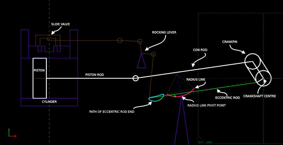
      Unfortunately, OnShape does not (as far as I know) have any means to get numerical data from the animation. I had a look for (free) mechanical design software and found, slightly to my surprise, that there was little suitable. Eventually I tried Solvespace, which is intended as a CAD solid modeller, but includes a constraint solver for mechanisms. I wouldn’t say that it’s the greatest, user experience-wise, but it does the job, and it can trace the path of selected points – this is relevant, because the valve rod connection in the similar, but simpler, Hackworth gear is supposed to trace an oval path. This design does not:

      FirthValveGear_JH

      The cyan coloured squashed oval object is the connection path with the radius link set at at the forward-reverse mid-point. Since the ends represent the extremes of the valve movement this means that the valve moves more or less at constant velocity in one direction, and shows continuous acceleration and deceleration in the other. Which doesn’t sound desirable.

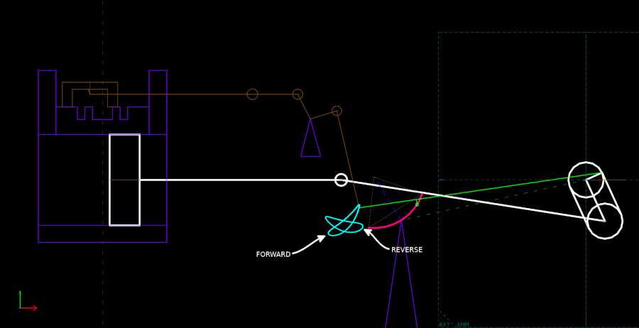
      It’s even worse at full forward or backward gear (edit: The curved link is in the backward gear position in the pic):

      FirthValveGear_20deg_JH

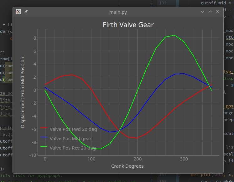
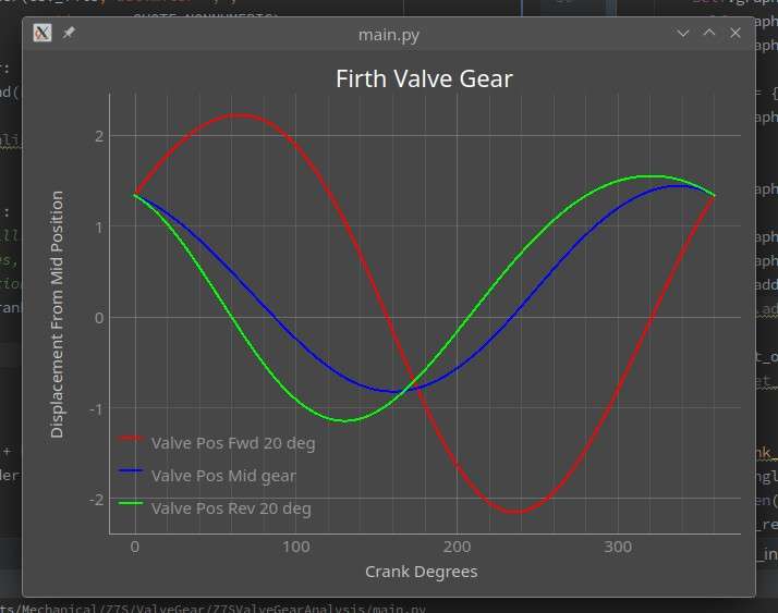
      I plotted the valve movement on a graph:

      ValveGearCurves

      (The ‘Mid Position’ referred to on the Y axis is actually zero at the extreme ends of the piston travel, front and back – I tried various ways to present these data and didn’t get round to changing the axis label).

      You can see on the mid gear curve that one section approximates a straight line, corresponding to the flat side of the traced path, whereas the other half of the cycle is more of a sine wave. The other setting are even worse.

      It’s clear that this isn’t going to work at all well, so, does anyone know the secret to getting Firth gear to work? It looks a bit similar to the Southern gear, but the eccentric rod is actually guided along the curved link, which is what generates its rather strange movement. I wondered if this is supposed to be cancelled out by the arcs that the rocker links travel through, but experiment seems to show that this isn’t the case.

      Advert
      #727999
      duncan webster 1
      Participant
        @duncanwebster1

        Have you exhausted the Dockstader simulations, available via this

        https://www.billp.org/Dockstader/ValveGear.html

        #728015
        Nigel Graham 2
        Participant
          @nigelgraham2

          It does not look an ideal gear for anything, but I don’t suppose Fowler reversed the geometry so that the forward gear was the one with the better steam distribution?

          Road vehicles, apart from rollers, don’t need work very efficiently in reverse so although still a compromise, making the forward gear the more accurate would at least partially “work round” the problem.

          So what happens if you move the eccentric setting 180º – putting it on the opposite “side” of the crankpin?


          The curvature of the radius-link may be the main culprit: the smaller its radius the more the distortion and this could be with a very small radius change.

          The Firth gear is new to me but it looks like a “straightened out” Hackworth gear.  I have observed when trying to trace a problem with a ‘Wren’ locomotive that with Hackworth gear the more the die-block guide is set from the mid-gear alignment the more the connection-point locus distorts from an ellipse to a stylised whale. I’ve think I’ve also found this on paper with the similar Marshall and Bremme gears. These simple radial valve-gears don’t like being over-driven.

          Tightening the radius link curvature might increase the effect, and success of this gear seems to depend on a fine balance between the radius and the angle to which the link is rotated.

          I do wonder why Fowler used this, and how they made it work: they didn’t cheat by using unsymmetrical ports or valves, did they?

          I’d suggest first seeing what happens with the eccentric put on the other side, then modifying the radius-link radius a very small bit at a time to observe the effects in full gears, mid-gear and a couple of intermediate notches in both directions.

          #728017
          Andy Stopford
          Participant
            @andystopford50521

            The only Dockstrader simulation I could find that seemed vaguely similar was the Southern – this could be a backup option, since I think it could be re-arranged to fit a traction engine layout, and look quite similar to the Firth design.

            Nigel – yes, I wondered why they went for this. It saves a bit on ironmongery compared with Stephenson’s, but since these were Fowler’s top models and doubtless very expensive it seems unlikely that was the reason. I read somewhere that as well as being used on ploughing engines, they used it for rollers – piston valved in both cases.

            I did try having the eccentric 180 degrees the other way, to no avail, also using a straight link a la Hackworth – in mid gear this looked promising, producing an oval trace, but forward and reverse suffered the same kind of ‘stylised whale’ distortion (at least I’ve got a name for it now).

            I should have mentioned that the above simulation was done using the dimensions from Haining’s ME articles – he does mention having spent a considerable amount of time trying to get it to work.

            It may indeed be that Fowler’s used some extra cheat to get it to work – I wonder which rollers it was fitted to; the ploughing engines with it seem to have only been superheated export models, it may be none exist now to find out how it was done.

            #728027
            Howard Lewis
            Participant
              @howardlewis46836

              If Fowler used it on Rollers, it would seem thatn they had found means of making the engine as reasinably efficient in nreverse as in forward gear.

              For a ploughing engine the heavy work mwould be in hauling the plough,and reverse running might be rarely needed (other than for manouvering), since th rope could be paid out using a brake to control drum speed.

              Would any full size Fowler enthusiast, ,or somone from Old Glory be able to throw more lightb onn the matter?

              Bear in mind that what worked in full mscale, may not function quites mwell when scaled down.

              #728114
              Paul Kemp
              Participant
                @paulkemp46892

                Firth valve gear was a joint collaboration between Fowlers and T Firth patented in 1905.  It is a development of Hackworth radial valve gear of 1859.  Maybe our resident patents expert can turn something up?  It was only used for the large Fowler compound ploughing engines, never on a roller and doesn’t seem to have been adopted by any other manufacturers or for any other uses.  Worth noting perhaps as designed and used by Fowlers it was employed on piston valves, the HP being inside admission (keeping HP steam away from the rod glands) and outside admission on the LP.  Reference is Traction Engine Design and Construction, G F A Gilbert pages 175 and a layout drawing on 179.  The main difference to the Hackworth gear seems to be Firth adopted curved rather than straight links.  I have a 2” Superba that was owned by my father but not built by him with the Haining version of the gear and it runs OK but I wouldn’t think it’s terribly efficient, it’s quite hungry for coal and water but it’s quite a low boiler pressure for any compound benefit at 90psi.  It’s not been out for a few years now though.  Somewhere in the family archives there is a set of original Haining drawings but I wouldn’t know where to start looking for them!

                Summary I guess is it’s quite a rare valve gear with little published detail so getting info is going to be difficult!  Perhaps try a post on Traction Talk?  Ross Bishop (suction hose) is well tuned in to valve gear.

                Good luck,


                Paul

                #728148
                JasonB
                Moderator
                  @jasonb

                  Might be worth seeing what MERL have on record, looks like they have the Firth Valve gear for the BBS and some of the valve parts for the Z7S. You could overlay Hainings ontop of those and see how things compare.

                  The BBS drawing is the same as the one in Gilbert’s book but will be a lot bigger at 3″ to the foot.

                  bbs

                  #728213
                  Andy Stopford
                  Participant
                    @andystopford50521

                    OK, so if not used for rollers, it might have been set up for running efficiently in one direction only.

                    I hadn’t got the Gilbert book, but Camden do it as a download so I’ve bought that (I didn’t fancy paying Abe books £175 for the paper version). Not ideal to read in a web browser, but never mind, it looks interesting anyway.

                    It appears that although the principle is the same as Haining’s, the proportions in the drawing are different. It’s hard to decipher the dimensions, but may be doable, or take a screengrab, and measuring from that would be worth a try since it’s the relative dimensions that are important. The caption says that the curved guide was to give quicker valve opening and shutting, which might be a clue as to what’s supposed to be happening.

                    The ideal, of course, would be the drawings from MERL, and I’ll look into what they’ve got; there are other details which might be available too.

                    Thanks for your help, chaps, I’ll post anything useful that I discover.

                    By the way, I wonder if the reason for using this type of gear may, in part at least, have been to allow a crankshaft centre bearing. Looking at the plan view, it would be a very tight squeeze to accommodate four eccentrics.

                    #728248
                    Nigel Graham 2
                    Participant
                      @nigelgraham2

                      It does seem that the basic radial gears are best for short valve travels: Walschaerts and Baker overcome the problem by adding the combination-lever.

                      The American builder, Case, successfully used a form of Hackworth gear, with straight link, on its traction-engines.

                      The Bremme version, using a swinging link in place of a sliding die-block, was effective on marine engines but those were intended to run at a fixed cut-off Ahead for days on end. Astern is normally only for short manoeuvres so an unsymmetrical action would not matter so much provided Ahead is efficient. The Marshall gear is similar to it.

                      All these gears work by constraining a pin-joint to an elliptical locus, and they normally give constant lead at all settings.

                      .

                      As you suggest, Fowler may well have used this gear for its compact nature, and my book from their era hints at similar reasons for marine-engine use, where the crankshaft needed plenty of big main bearings. Such gears also use less metal and less joints.

                      #728864
                      Andy Stopford
                      Participant
                        @andystopford50521

                        Well, some progress. I used the dimensions, in so far as they could be ascertained, from the Fowler drawing, and the results looked far more promising.

                        This is the path traced by the eccentric rod end for forward-, mid-, and reverse gears (ignore the vertical lines):

                        FromFowlerDrwg

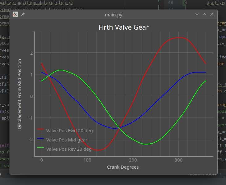
                        And this is the plot for valve movement:

                        CurvesFowler

                        The slight lumpiness is probably down to the difficulty of rotating the crankshaft to exact values in Solvespace (you can do it numerically, but the process is rather tiresome).

                        So not, perfect, but getting there.

                        I noticed that in the glossary of Traction Engine Design and Construction he gives the patent number and date for Roger Firth’s invention, and I was able to find it:

                        https://worldwide.espacenet.com/patent/original-document?channel=espacenet_channel-2f10bce5-d460-480e-9922-a9203170141f

                        To be honest, it’s not particularly helpful, but it confirms that the advantages are quicker opening/cut-off and allowing a more compact or better supported crankshaft.


                        #728874
                        Andy Stopford
                        Participant
                          @andystopford50521

                          A slightly improved version (with the direction of the curves reversed which makes more sense to me – I think):

                          CurvesFowlerOrig

                          #728901
                          duncan webster 1
                          Participant
                            @duncanwebster1

                            Andy, I’ve sent you a pm

                            #788390
                            Andy Stopford
                            Participant
                              @andystopford50521

                              An update:

                              I ended up building a simulation in FreeCAD using the Assembly3 workbench, and a Python program to display the results graphically (thanks to Duncan Webster for sending me some information on valve gear design), and ran many, many test of different configurations of the Firth gear.

                              I found that it was possible to get a pretty much perfect distribution for both ends of the piston stroke, and forward and backward directions. Unfortunately, this could only be obtained by (considerably) lengthening the rocker arms so that, effectively, the distortion that this introduces counteracts the intrinsic distortion from other parts of the valve gear, but with the undesirable effect of imparting excessive side thrust to the valve spindles.

                              I decided to splash out on getting copies of the works drawings from MERL. There aren’t very many for the Z7S, but there is an arrangement drawing for the motion gear (drawing no. 57361), and although it isn’t dimensioned, printed full size on A0 paper it’s possible to measure dimensions from it accurately enough (especially given the fact that it’s going to end up scaled to 1/12th).

                              I found it was very different from the John Haining drawings – I guess that he had to do considerable alteration to get it to work with slide valves. I’m going to go with the original piston valves, which may be challenging at this scale, but what the hell, the whole thing’s going to be challenging.

                              The valve event plots look pretty reasonable – good enough to be getting on with designing the rest of the engine, though there could be room for some tweaking later (annoyingly FreeCAD proved very cranky doing this, and now refuses to get the previous simulations to work – there is a new assembly module in version 1.x and I’ll try re-building everything in that to re-test).

                              At the Tinker’s Park steam rally last year, I asked the owner of a BB1 if he knew anything about complications with the Firth gear – he said he’d never heard such, and pointed out that at the speeds these engines worked valve event perfection may not have been that important.

                              It works in Onshape anyway:

                              https://vimeo.com/1064855329

                              #805260
                              mecheng47
                              Participant
                                @mecheng47

                                Andy – I’m interested in this string on Firth Valve Gears.

                                I have an almost finished John Haining designed Superba, built as a piston valve using the MERL Z7S cylinder piston valve liners.  And, yes – Gilberts books are excellent.

                                Like you I tried an early version of Onshape and Fusion 360 to reproduce a dynamic model – not then available. And, I built a full-size ply model of JHs design and decided it was no good for piston valves.

                                I also have the undimensioned GA Fowler drawing and I ignored Rule number One and scaled it off and built it.  However, although the engine has not steamed yet – it runs passably on air.  Ahead running is much neater than reverse.

                                I did a valve measurement from the model and got similar results to your plots.

                                I think all the mentioned valve gears in the string are Hackworth radials in basic form, often with their own names and minor variations. And probably you are right the singe eccentric allowed room for a middle bearing on the crank shaft.

                                What makes this gear unique is the offset for the pivot.

                                A friend here has a full-size American Case (Hackworth straight guide) and with an offset pivot. This makes the Firth gear and the Case Gears different from the standard Hackworth and variants.

                                I have tried to get this engine (single Cylinder) to stop on dead centre — it will not!  This appears to be a feature of the gear on the Case.

                                Both the Superba /Z7S and the Case were designed as single direction machines.

                                There is a Z7S being restored in the UK with some excellent comments in the Steam Plough Club quarterly publications.

                                #805320
                                Andy Stopford
                                Participant
                                  @andystopford50521

                                  Thanks for your observations – it’s interesting to hear from someone who’s actually built a piston valve version and who’s gone down the same route trying to figure out how to get it to work properly.

                                  I’d begun to suspect it was single direction only – without the over-length rockers it seemed impossible for it to perform anything like equally in both directions, though I have wondered whether changing the shape of the guide from a simple arc to something more complex would do the trick – very non-original of course, and, like Fowler’s 100+ years ago, I have no CNC facilities for its production (other than a 3D printed mock-up, which might be interesting, and possibly easier than trying to persuade FreeCAD to simulate it).

                                  I see the Steam Plough Club has a stand at the Weald of Kent Steam Rally in August so I’ll ask them about the one being restored – I hadn’t realised there was a Z7S in this country, apart from the one that’s been converted to a diesel.

                                  #805364
                                  SillyOldDuffer
                                  Moderator
                                    @sillyoldduffer

                                    Fascinating thread.

                                    Several reasons why folk invented different valve gear:  patent dodging, reduced maintenance, improved reliability, and being able to fit into a tight space etc.

                                    As I understand it, Stephenson’s gear produces near perfect events, but is expensive to make and a pig to maintain when the gear is under the boiler and between the wheels.   During the 19th century many attempts at alternatives, of which the best is  Walshearts.  Not quite so good as Stephenson events, but much easier to maintain because it’s mounted on the outside of the wheels.

                                    As Walshearts is somewhat complicated, interest in alternatives continued, especially for road vehicles.  They aimed at some combination of being lighter, smaller, with fewer joints, cheaper, and/or simpler to set up and mend.  All compromises, usually with inferior events that waste fuel, and not notably more reliable either.

                                    Fuel economy doesn’t matter if the application favours simplicity, size or reliability, but it does tend to discourage wastefully over-simple valve gear.  I think Firth was a brave attempt at a compromise suitable for traction engines but it didn’t outshine other gear in practice, and never became popular.   It is what it is!   And then internal combustion put an end to traction engines…

                                    Plenty of interest in studying Firth though, and Andy’s clever efforts with FreeCAD, Python and Onshape might well bear fruit.  He could find an optimisation missed by Firth/Fowler because they didn’t have time to wade through all the possibilities.

                                    More please!

                                    Dave

                                    #805387
                                    noel shelley
                                    Participant
                                      @noelshelley55608

                                      Very interesting thread ! In the supplement to GFA Gilberts Traction Engine Design and Construction, Page 64 and 65 are 2 pictures that may be of use or interest, the engine used Firth gear. Noel.

                                      #805394
                                      Nigel Graham 2
                                      Participant
                                        @nigelgraham2

                                        AsDave says, this is a fascinating thread.

                                        Previously I had not even heard of Firth Gear though I know there were quite a variety invented, of link-motions, radial-motions and assorted cam-drives.

                                        I am not sure where the Mann steam-wagon gear fits, but I think radial. It uses a slotted eccentric moved across a square on the crankshaft, so was relatively simple, very compact and might give near-“perfect” valve-events although with harmonic rather than the rapid-action valve-travel of Stephenson’s gear.

                                        Stephenson’s Link Motion was probably costly to make simply because it contains so many parts: 11 or 12 between crankshaft and valve-spindle, omitting the reach-rod and control, and valve-spindle guide; and neglecting assorted pins, keys and fastenings.

                                        Walschearts’ Gear (radial) has about eight per cylinder even if discounting some parts, such as the expansion-link and its lifting arm, being divisible into further bits.

                                        One might imagine the most difficult and expensive component was the curved expansion-link, common to both gears; and that on locomotive’s Walschaerts Gear was sometimes assembled from several pieces. I doubt it was really very difficult, industrially.

                                        Its critical area, the arcuate slot, could be shaped relatively easily using a slotting-machine with power-driven rotary-table, albeit starting with a large, drilled hole then cut in two episodes. I think an ME contributor (Doug Hewson?) pointed out fairly recently the links on some locomotives were made in four parts: two curved arms bolted together with intervening, large spacer-blocks. The really awkward bit may have been machining the outline!


                                        The American company, Case, used a variation of the deceptively-simple Hackworth Gear (radial) on its traction-engines. This, if designed and set correctly, can give fairly good results from very few, easily-made components but such niceties were less of a consideration than sales and servicing cost when applied to very basic, narrow-gauge, industrial-site locomotives such as the Kerr, Stuart “Wren” class.

                                        #805760
                                        Martin Johnson 1
                                        Participant
                                          @martinjohnson1

                                          Just thinking that Marshall used a sililar radial gear on their rollers but that has a straight slide.  The Firth is also similar to Woolf gear.

                                          Looking at the OP’s diagram, I wonder if the curved slide has been “assembled” wrong way up.  If the slide was convex upward it would curve the upper half of the point path diagram and straighten the lower half, thus better approaching the elipse that is needed.

                                          Martin

                                          #805824
                                          Andy Stopford
                                          Participant
                                            @andystopford50521
                                            On Martin Johnson 1 Said:

                                            Just thinking that Marshall used a sililar radial gear on their rollers but that has a straight slide.  The Firth is also similar to Woolf gear.

                                            Looking at the OP’s diagram, I wonder if the curved slide has been “assembled” wrong way up.  If the slide was convex upward it would curve the upper half of the point path diagram and straighten the lower half, thus better approaching the elipse that is needed.

                                            Martin

                                            It’s an interesting thought, but the slide is that way up in Fowler’s drawings. The diagram at the top of this page is from John Haining’s design which seems very far from what’s desirable. Taking the dimensions from the Fowler works drawings gives a much better ellipse:

                                            FromFowlerWorksDwg

                                            #805886
                                            Martin Johnson 1
                                            Participant
                                              @martinjohnson1
                                              On Andy Stopford Said:
                                              On Martin Johnson 1 Said:

                                              Just thinking that Marshall used a sililar radial gear on their rollers but that has a straight slide.  The Firth is also similar to Woolf gear.

                                              Looking at the OP’s diagram, I wonder if the curved slide has been “assembled” wrong way up.  If the slide was convex upward it would curve the upper half of the point path diagram and straighten the lower half, thus better approaching the elipse that is needed.

                                              Martin

                                              It’s an interesting thought, but the slide is that way up in Fowler’s drawings. The diagram at the top of this page is from John Haining’s design which seems very far from what’s desirable. Taking the dimensions from the Fowler works drawings gives a much better ellipse:

                                              FromFowlerWorksDwg

                                              That looks more like it!

                                              B.t.w I am working from a Kerr Stuart drawing which shows the motion brackets back to front.  Drawing office wallahs are fallible.

                                              Martin

                                              #805899
                                              duncan webster 1
                                              Participant
                                                @duncanwebster1

                                                <p style=”text-align: left;”>As others have said, this is a Hackworth type gear, but as the vibrating lever is quite long it wont suffer as badly from angularity, at least of this component.  I have found with Hackworth that having a curved slide with radius substantially less than the length of the valve rod gives better results. Might be worth experimenting. The angle between the arms of the bell crank will also have an effect.</p>
                                                Amazing how many people lay claim to this gear. As others have said it’s very similar to Southern, and a chap called Brian Remnant had a Sweet Pea fitted with a similar set up but he called it Bremme.

                                                I’m not into animated CAD models, but if anyone wants to have a go at a mathematical model give me a shout and I’ll send my Hackworth written in Python code as a starter for 10.

                                              Viewing 22 posts - 1 through 22 (of 22 total)
                                              • Please log in to reply to this topic. Registering is free and easy using the links on the menu at the top of this page.

                                              Advert

                                              Latest Replies

                                              Home Forums Traction engines Topics

                                              Viewing 25 topics - 1 through 25 (of 25 total)
                                              Viewing 25 topics - 1 through 25 (of 25 total)

                                              View full reply list.

                                              Advert

                                              Newsletter Sign-up