I have an 8 ohm 1 watt speaker that I want to drive with a square wave off 24v. Just to sound an alarm. I think I can do this by putting a big capacitor in series, but anyone got any idea as to value? My memory of resistor/capacitor calculations is more than a bit creaky, and it’s not a sine wave, which probably complicates the issue.
I wouldn’t worry about the difference between a sine wave and a square wave. By the time a square wave has been through a capacitor and speaker coil, it won’t be very square!
The speaker impedance is 8 ohm, almost all inductive i.e XL.
To bring the speaker and capacitor to resonance, we need 8 ohms capacitive i.e Xc,
Impedance varies with frequency, so we need to know what it is.
C = 1 / 2πfXc
If f = 250Hz, then
C = 1 / 6.28 * 250 * 8 = 0.000079618 Farads, or 80µF
By proportion, 500Hz would need 40µF and a 1000Hz tone wants 20µF
I think a 47µF or 100µF standard electrolytic would do for most audio frequencies.
If maximum noise is required, then a ceramic resonator pinched from a fire alarm might be better than a speaker. They’re scientifically tuned for maximum sound penetration into human ears, like to be fed square waves, and don’t need a capacitor. Very high efficiency at their operating frequency, otherwise poor, so not good for anything other than loud alarms.
We need some more information in order to answer your question properly.
You say you are driving the speaker with a square wave off 24 volts. Do you mean the square wave has an amplitude of 24volts, and is it 0-24 volts, or +/- 12 volts?
What is the impedance and power capability of the driving source, and what is the frequency of the square wave?
If the source is low impedance and the amplitude really is 24 volts peak to peak it will likely destroy your 8 ohm speaker rated at 1 watt, or itself be destroyed. If the source is high impedance it may be incapable of driving a low impedance speaker.
A 24V square wave will put about 18watts into an 8 ohm speaker. A 1 watt speaker will immediately destruct due to over-excursion and probably break the connections before it has a chance to melt…
I suggest using a small capacitor, say 1uF, and it should turn the signal into a series of opposite polarity pulses that generate a suitably unpleasant sound for an alarm.
In detail this will create a high pass filter (1uF and 8ohms will be about 20KHz) which may seem far too high but in practice this will kick the speaker alternately in and out at the frequency of the square wave. Experimenting with increasing the capacitance will make the audible tone louder and you can keep trying until you get an acceptable result without the speaker getting warm.
However I must have been having brain fade when I asked the question, I have 5v derived from a 7805 to drive the Arduino, so I can use that to drive the speaker, with a 5 ohm series resistor. It’s also dawned on me that I could use the pwm output and drive less than half time, something to experiment with over Xmas
If the speaker was in series with a transistor across the 24v Dave’s sum falls down as its only conducting half time, so 36W
…
Time is a vital factor in Duncan’s question, so all our guesstimates are a bit suspect. Also, we’ve all made assumptions, with Neil assuming a 24Vrms amplifier, whereas I assumed a 24Vdc rail. Both wrong, Duncan now says it’s a 5V rail!
Anyway, consider what happens in my circuit above.
the rail holds steady at 24V (unless the power supply is rubbish!)
when the transistor switch is OFF, the capacitor charges via the 470ohm resistor and the speaker. Doesn’t charge instantly, because the 470ohm resistor inhibits current flow, as does the speaker, a bit. The speaker’s cone moves OUT in time with the current flowing in the capacitor as it charges up.
when the transistor is switched ON, the capacitor discharges through the 8ohm speaker. Current flow in the speaker is reversed, and the cone pulls IN. The 470ohm resistor does nothing beyond wasting a few DC watts. Instead the time taken to discharge the capacitor is proportional to its value and the 8ohm inductance of the speaker. My earlier post calculated the capacitor needed to resonate with the speaker, more explanation below. For this I took time into account, hence 2πf in the formula; C varies with frequency.
The amount of power that can be delivered to the 1W rated speaker is limited by the 470 ohm resistor. The circuit doesn’t apply the full power available from the 24V rail to the speaker.
Note the graph shows that the charge current flowing in the speaker isn’t a square wave. The sharp rise is converted into a rounded curve by the RC time constant. Not a sine wave, but far from square.
Different maths applies when the transistor switches ON and shorts the capacitor to ground. This speaker coil is an inductor, not a resistor, and inductors also have a time constant. Inductors and capacitors both store energy, but they do so in the opposite sense. Thus, when a capacitor discharges into an inductor, it charges the inductor. Then the current flow reverses and the inductor discharges into the capacitor. The LC time constant is resonant at some frequency, so LC circuits oscillate at a particular frequency, and the output is a sine wave.
My circuit is akin to banging a drum. The transistor switching OFF sends a rounded pulse of energy into the speaker cone. Shortly after, switching ON causes the LC combination to oscillate.
If the speaker was a perfect inductance, the LC combination would oscillate for many cycles, and the output would be a sine wave. Speakers are far from being a perfect inductance though. Some energy is lost as heat due to wiring resistance, and a massive amount due to stirring air with the cone. The speaker is more motor than inductive load, mechanically converting electrical energy into sound. Accelerating the cone and pumping air also take time, making the exact waveform hard to predict accurately. Something like this though:
Much closer to a sine wave than square. In terms of power consumption the waveform is roughly 50% duty cycle. Duncan’s idea of using Pulse Width Modulation is interesting. PWM produces a rectangular wave with a duty cycle anywhere between 05 and 100%, his choice. In effect, PWM allows the drum to be beaten more or less heavily, altering volume and the wave shape.
Maths and theory applied competently get circuit values in the right ball-park. In this case, I’d experiment for best results. For example, the speaker will be most efficient when the electrical resonance is tuned to its mechanical resonance. However, this could be too much for the construction, as when opera singers shatter wine glasses! A cheap speaker rated for 1W with a normal audio spectrum, might not be able to sustain that promise at resonance. (More expensive speakers are designed to avoid resonances within their operating range because resonances disturb music lovers. Done by reducing speaker efficiency, which is why I suggested a ceramic disc. They go for maximum efficiency at a particular tone, producing a nasty waveform that’s very loud!
Beware: I often get maths wrong, and haven’t tested my conclusions by wiring one up!
A 24V square wave will put about 18watts into an 8 ohm speaker. …
Neil
Is it me? I reckon 72W from W=V*V/R
Just for the record: P=V^2/R works for DC or RMS voltages.
A 24V square wave (i.e. 24V peak to peak generated, for example, by switching on and off a 24V supply) has an RMS voltage of 12V. (cf 8.5V for a sine wave of the same amplitude).
Power into 8 ohm is thus 18W (from V^2/R)
1W into 8 ohm requires 2.8V RMS, so a 5V square wave should be suitably within the speaker’s rating.
(Capacitor still required for DC blocking; exact value not critical (in the range 1uF -> 100uF), but will affect volume, depending on the frequency of the signal.)
Sorry for the confusion. I have 24v supply (provided by others) which I’m using to drive a relay, so I just assumed I’d use it to drive the audible alarm. I’m making this out of junk box components as far as possible, hence the speaker rather than a piezo buzzer. It simply hadn’t occurred to me to use the 5v supply to the Arduino, brain fade.
However, I’ve just measured the DC resistance of the 8 ohm speaker with digital meter, and it’s 7 ohm, so SOD ‘s assumption of inductive load might be invalid. I like his circuit tho, it converts the open collector I had in mind to a bi direction, in fact I don’t think my original idea would have worked at all, so this discussion has saved me some frustration
However I must have been having brain fade when I asked the question, I have 5v derived from a 7805 to drive the Arduino, so I can use that to drive the speaker, with a 5 ohm series resistor. It’s also dawned on me that I could use the pwm output and drive less than half time, something to experiment with over Xmas
It depends.
I assumed a 24V square wave relative, as in 0v-24v, not a sine wave.
But my calculation assumed a large capacitor was used to decouple the square wave, so it would be alternating between +/- 12V across the speaker, so the average RMS voltage would be SQRT((12×12 + -12x-12)/2) = 12.
For a sine wave a 24V P-P signal would give 0.707 times that value = ~9V.
If the square wave is connected directly across the speaker without a decoupling capacitor, it alternates between 0v and 24V so the RMS value is SQRT(24^2/2) = ~17V
Maths and theory applied competently get circuit values in the right ball-park. In this case, I’d experiment for best results. For example, the speaker will be most efficient when the electrical resonance is tuned to its mechanical resonance. However, this could be too much for the construction, as when opera singers shatter wine glasses! A cheap speaker rated for 1W with a normal audio spectrum, might not be able to sustain that promise at resonance. (More expensive speakers are designed to avoid resonances within their operating range because resonances disturb music lovers. Done by reducing speaker efficiency, which is why I suggested a ceramic disc. They go for maximum efficiency at a particular tone, producing a nasty waveform that’s very loud!
Beware: I often get maths wrong, and haven’t tested my conclusions by wiring one up!
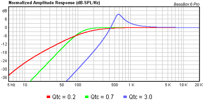
For most speakers, the resonant frequency is effectively their low-frequency cut-off, below which the speaker becomes less efficient. You can’t avoid the resonance of the driver, it’s an inherent property of the driver. What you do is tune the enclosure (either by choosing a specific volume or making it into a tuned cavity by using one or more ports) to flatten out the resonant peak into an extended bass response. The ‘shape’ of the curve will depend on intended use, as for some applications a bit of a ‘hump’ at the bottom of the range is useful, or you can trade extended response for reduced efficiency.
Below in the blue example the resonance at 600Hz could cause problems (Qtc is the inverse of the damping ratio i.e. a measure of resonance).
The green line is an ‘ideal’ response for a flat response speaker.
The red line is over-extended so you don’t get any useful extension compared to the green line.
As a bass player, I’m very into what happens with bass cabs. It’s incredible what you can get these days compared to forty years ago!
For the last couple of years I’ve been using one of these at-212-slim. This sounds amazing with music played through it, although it does have a very slight ‘mid scoop’.
For interest, here’s a comparison I made between two speakers, you can see that the more efficient speaker with better response below 40Hz starts to drop off around 500Hz (but only -2dB as the x axis is stretched a bit).
Maths and theory applied competently get circuit values in the right ball-park. In this case, I’d experiment for best results. For example, the speaker will be most efficient when the electrical resonance is tuned to its mechanical resonance. However, this could be too much for the construction, as when opera singers shatter wine glasses! A cheap speaker rated for 1W with a normal audio spectrum, might not be able to sustain that promise at resonance. (More expensive speakers are designed to avoid resonances within their operating range because resonances disturb music lovers. Done by reducing speaker efficiency, which is why I suggested a ceramic disc. They go for maximum efficiency at a particular tone, producing a nasty waveform that’s very loud!
Beware: I often get maths wrong, and haven’t tested my conclusions by wiring one up!
For most speakers, the resonant frequency is effectively their low-frequency cut-off, below which the speaker becomes less efficient. You can’t avoid the resonance of the driver, it’s an inherent property of the driver. What you do is tune the enclosure (either by choosing a specific volume or making it into a tuned cavity by using one or more ports) to flatten out the resonant peak into an extended bass response. …
Below in the blue example the resonance at 600Hz could cause problems (Qtc is the inverse of the damping ratio i.e. a measure of resonance).
The green line is an ‘ideal’ response for a flat response speaker.
The red line is over-extended so you don’t get any useful extension compared to the green line.
…
Not misinterpreted, rather Neil and I are at cross-purposes.
I was tightly focussed on the electronic aspect of Duncan’s question : how to drive a 1W 8Ω speaker with a square wave. Nothing HiFi about Duncan’s requirement – his application is an alarm, where loud and piercing are the bees knees, not bass response.
Neil’s comments address a different aspect of loudspeaker design – how best to enclose the mechanical speaker. The box a speaker is mounted in is important too, especially when playing music. But this is acoustics rather than electronics. Acoustic engineering also deals with the resonance and distortion of waveforms, but they’re sound waves moving in air. And it’s complicated – the speaker and its enclosure have to be optimised, and then – ideally – the room matched to the speaker. Thought the Sydney Opera House has a striking exterior, I’m more impressed by the audio performance of its interior.
Anyone else remember the good old days at Paddington, where announcements sounded like: ‘The tra, tra, ain, now ow ow, st, st, anding a at Pla, pla t form, rm, two oo oo is the nu nu ine ten for Ca ca ard if if’. This was the best a 1930 PA system and horn speakers could do in a big echoing building without spending a fortune!
HiFi takes engineering design into complicated territory. In Neil’s bass guitar, the pick-up will have been designed to produce a flat response over the range of tones produced by the strings, and although it will also do a good job with overtones and harmonics, higher pitched guitars are probably fitted with pick ups that suit their frequency range. These pick-ups need to be accurate rather than efficient, because low signals are easily amplified electronically.
The signal is normally fed into a pre-amplifier, designed with a flat response to increase the signal level without distorting it. The output could be fed directly into a power amplifier, but more likely there will be a processing stage. The processing could be as simple as a Tone control, or a basic graphic equaliser, or an advanced graphic equaliser plus other gizmos. The purpose, in so far as possible, is to compensate electronically for shortcomings in the pick-up, amplifiers, and loud speaker system.
In my youth, audio systems were entirely analogue. Worked well if a lot of money was spent on them, but with many limitations, and they were noisy and tended to sound a little mushy or other wise tainted compared with live music. Filtering is particularly difficult to do well with analogue components, for example a sharply tuned high-Q inductor/capacitor combination rings like a bell because the components store energy. The filter has to be backed off to avoid ringing, not good.
Digital processing is much better at cleaning up and manipulating signals than analogue. The signal is converted into a stream of numbers that can manipulated mathematically. Implementing a digital filter that doesn’t ring no matter how sharply tuned is trivial. A bit code like:
getInput:
read sample
if sample < 999.9 or sample > 1000.1 then goto getInput
And much, much more can be done. See Cher Effect which was a novel use of Autotune – a device that corrects off key singers on the fly, so what reaches the speaker is correct.
Fascinating stuff and worthy of long discussion, but a long way from Duncan’s requirement, which is how to make an Arduino make a nasty noise as an alarm!
I don’t want to argue Dave, but for interest some thoughts about bass amplification.
The frequency response and output of pickups can vary hugely. Overwound pickups can be especially ‘hot’ as can pickups with strong (e.g. neodymium) magnets. Humbuckers with dual coils sound armer than single coils. The nature of the windings has a big influence, as does the wiring (series or parallel) of multi coil pickups. An output of about 1V RMS is not untypical. Most tone shaping pedals run off 9V but it’s not unsual to find pedals running 12V or even 18V to provide extra headroom.
Active instruments usually offer comprehensive and usually excessive tone shaping. Active preamps typically boost signal levels by 3-10dB; ironically better amps often have a -10dB ‘pad’ switch to counteract this!
Bass pickups have to cope with a much wider range than typical guitar pickups. They can go well over an octave below guitars (think ~30Hz as against 84Hz) but percussive styles often need more top end than guitars. Many bass cabs have tweeters, but few guitar cabs do. In practice although there are many different pickups, in practice most differences between bass and guitar relate to string spacing and number rather than impedance, number and wiring of coils, magnet type or wire gauge (the things which affect response).
Instrument amplifier preamps are the main place for tone shaping. In most solid state amps the input stages are designed to deliver desirable sounds from being overdriven as overdriving the output stages sounds harsh. Valve amps are often lower wattage and the output stages can be driven hard into distortion.
Increasingly, amps with valve front ends designed to be overdriven and class-D output stages (with near perfect transfer curves) do the heavy lifting with huge headroom (because you really don’t want to clip a class D amplifier).
Most bass amps are designed with some sort of mid-scope when the eq is at the middle settings – Trace Elliot, Orange. Ashdown, Fender Rumble are classic examples of this. On the other hand, some amps (Markbass) have a very neutral sound.
And yes modelling amps that CLAIM to be able to reproduce multiple amplifiers (and even speaker cabinets) and are often used with full-range flat response (FRFR) cabinets to add minimum colour. I have a guitar amp that combines digital processing with a preamp valve for fairly convincing sounds, but my general view is that modelling amps are ‘jack of all trades, master of none’, though they continue to improve.
An interesting difference between bass and guitar amps. Because of the way the ear responds to different frequencies the perceived ‘loudness’ of the lowest notes is 10dB (or more) quieter than a guitar at ‘gig volumes’. That’s percieved as less than half as loud. This means bass amps need to be several times more powerful. Our guitarist uses 15-50W amps, I use a 500W amp, but that’s not as dramatic as it sounds, 500W is only twice as loud as 50W and only four times as loud as 5W. Plus he’s using overdriven valve amps, I have a valve/class D hybrid played with headroom on the output.
You mention autotune. A curse that should be banished from the face of the Earth. Why on earth does someone with Michael Buble’s skill use it?
Other digital effects can be very clever, I have a box that can take chords, deconstruct into the separate note for each string and output an octave up and down, with minimal latency (just milliseconds). That said, I increasingly feel effects are just that – special effects that should be used sparingly, if at all.
There’s also huge debate about ‘tone woods’ which i’m not going to detail!
Not much to do with model engineering, but there’s a lot of interesting engineering going on in electric instruments!
I tried SOD’s circuit, and it worked, but more searching in the junk box unearthed a 64 ohm one. Simply driving this in one direction by putting a transistor in series makes a loud enough noise. More scratching at the back of my memory suggested that using 2 transistors in push pull with the speaker connected one end to the mid point and the other end via a cap to ground.
Author
Posts
Viewing 18 posts - 1 through 18 (of 18 total)
Please log in to reply to this topic. Registering is free and easy using the links on the menu at the top of this page.