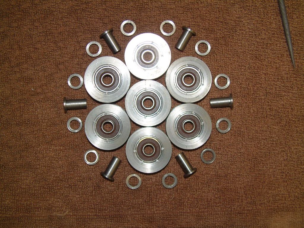
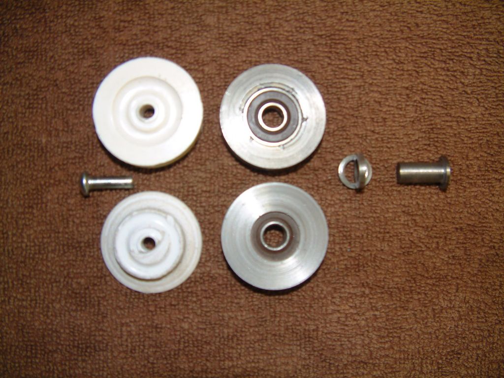
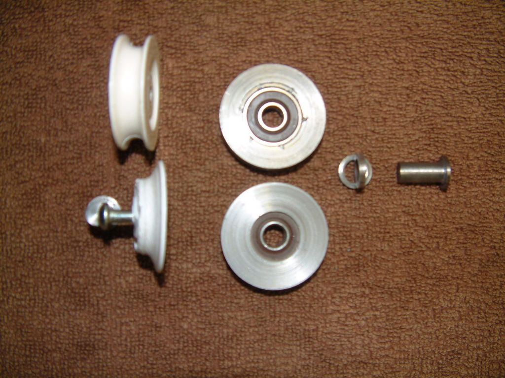
The method of realigning the axle holes is also determined, as I have proven with the first three examples.
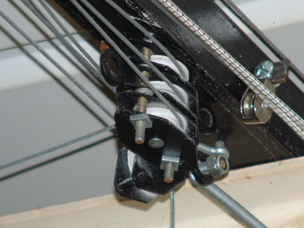
Due to the manufacturing methods adopted by the makers of the original pulleys, the sheaves (or frames of the pulleys) are adequately strong in construction but the axle holes do not align accurately enough to allow our revised design of pulley to locate between the sheave cheeks correctly. to overcome this fault I have adopted a method of drilling and milling to correct this.
It involves three stages of operation, with the sheave firmly gripped in the machine vice of the bench drill, a first stage 6mm drill is used to drill the upper cheek of the sheave, this drill is then replaced with a 6mm end mill and the lower cheek is carefully milled in alignment with the upper cheek, finally, the milling cutter is again replaced, but this time with an 8mm sharp drill and this drills both cheeks to complete the process.
The sheave is then de-burred and the ball bearing pulley and its spacers are assembled in the sheave and the prepared axle passed through the assembly, the 1/2mm projecting axle is then peened over to finally anchor it in place.
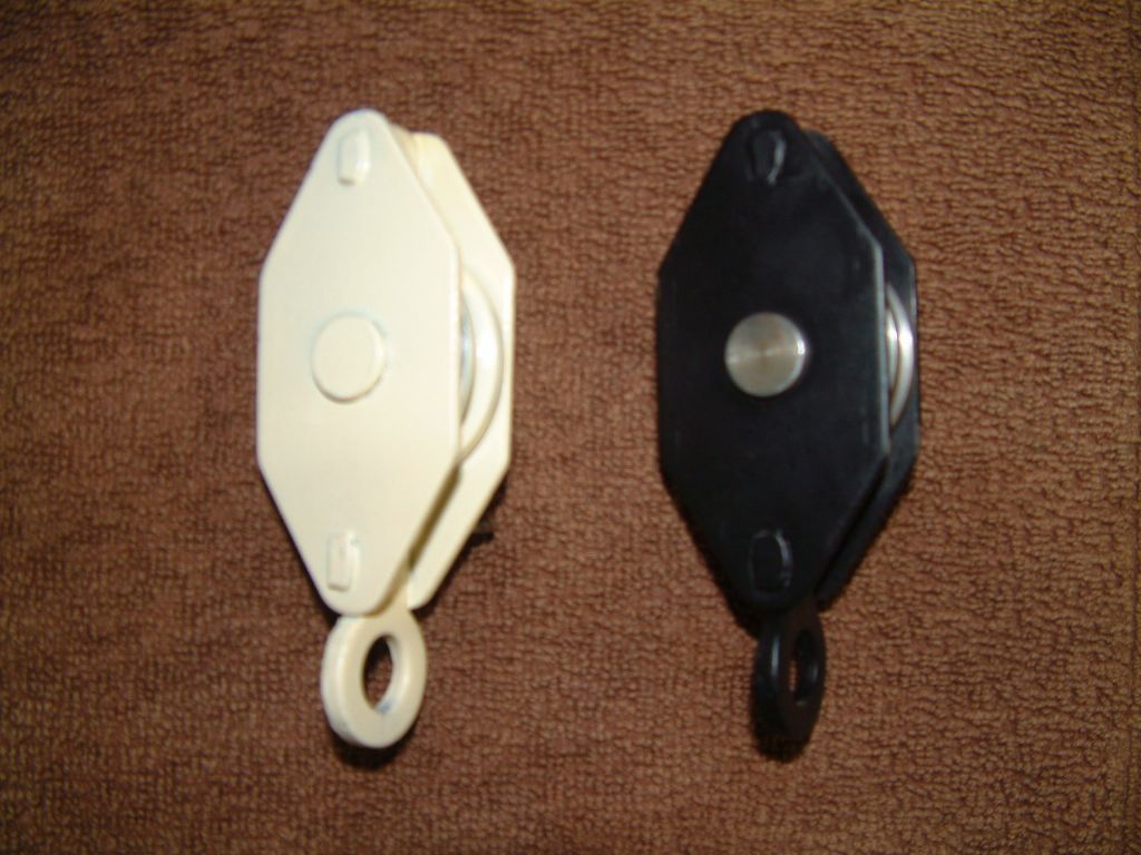
Thus renewed, will then be painted in the ever popular shade of Magnolia prior to being refitted to the lift mechanism to match the existing metal building frame, I intend this colouring match to spread to the exposed underparts of the layout to make the layout to blend in with the existing colour scheme and hopefully make the hanging layout less intimidating to both members and visitors alike.
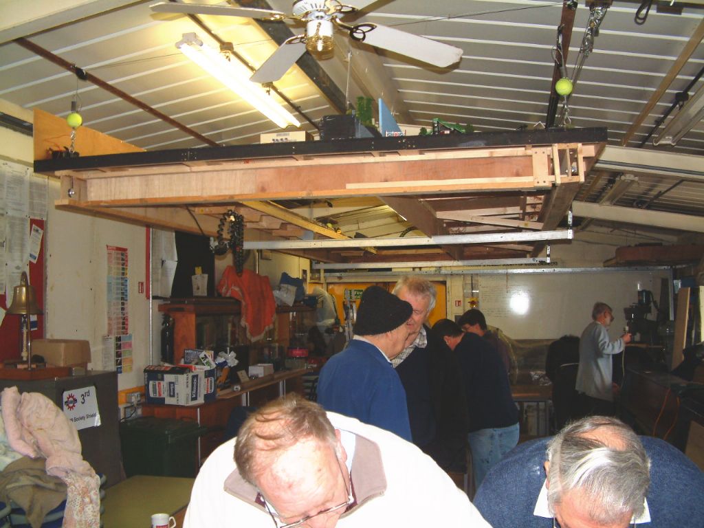
During the revision work of the layout, the existing pulleys will have to have their pulley wheels removed, the sheave drilling operation performed and re-assembly with the new parts completed, then finally painted before re-use, so my preparative work should save time during the major operation of adding new lift positions (there will be eight, at present there are six) to equalise the support during lifting, this has become necessary due to the increased weight encountered by extensions to the extended surface area of the present layout.
This weight increase has nothing to do with eating habits, but is more to do with carrying unexpected luggage, all the rolling stock is now left on the layout and the extra support timbers to fix the extensions,, together with the scenic features permanently attached, has increased the overall weight threefold from the original, at the last weigh in it was 600 lbs.
I shall be weighing it again during the refurbishment work and I hope it is still within the designed lifting capability of the hard pressed hoist mechanism in its present configuration, if it is close, further provisions to carry the extra weight will have to be introduced, (another loop of lifting cable to reduce the pull to a quarter of the total weight, at present it is one third)
My fears are for the hoist motor, gears and brake, the pulleys and cabling are well within their capability but stepping over the designated capacity of the hoist is asking for trouble, and none of us want that, least of all, me !


