Another Arduino-controlled pendulum clock

Advert

Another Arduino-controlled pendulum clock

Home Forums Clocks and Scientific Instruments Another Arduino-controlled pendulum clock

Viewing 25 posts - 1 through 25 (of 63 total)
  • Author
    Posts
  • #508157
    John Haine
    Participant
      @johnhaine32865

      img_20201118_091651197.jpg

      A while back I posted a couple of replies in the thread that SoD created on his experimental clock on something I was playing around with. I thought I'd create another thread with more details to avoid confusing Dave's thread. The photo shows the nearly complete clock which is now sitting on my desk keeping reasonable time. It doesn't actually lean over to the right, that's just the photo!

      The pendulum is to the rear of the clock, suspended from a bracket mounted on two brass channel uprights. Also attached to these is the dial, a commercial dial plate from Meadows & Passmore mounted in a shallow tray CNC millied from 1/4 inch aluminium. Movement is a converted quartz, with the stepper coil disconnected from the IC and brought out on a couple of thin wires. Arduino Nano is mounted on a small bit of perf board on spacers from the plate below the dial. Pendulum rod (bit of 6 mm CF tube) suspended from double spring, brass bob about 75mm long clamped by set screw from behind. 12 x 3 mm Neo magnet in the end of the tube.

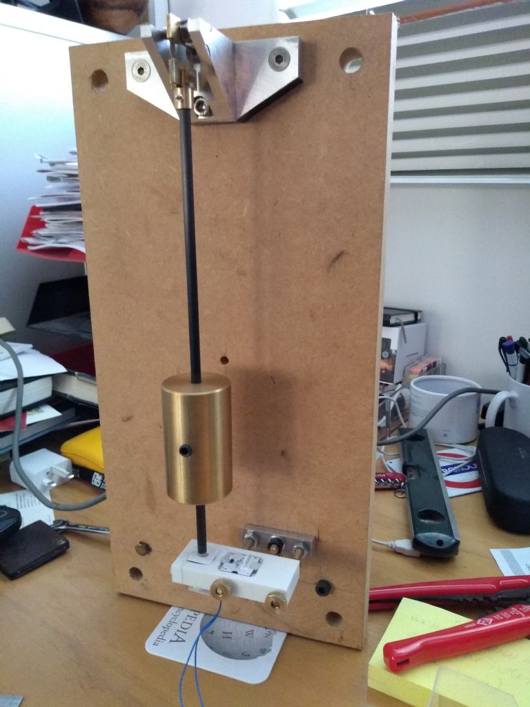
      img_20200929_173004256.jpg

      This is the back view of the former lash-up. The white block at the bottom has the impulse coil directly below the centre position of the pendulum, and a Hall effect sensor to the right that detects the magnet on its swing extreme to control amplitude. The block is now mounted slightly differently with adjustable height from the aluminium base.

      I was very much using bits from the scrap box in making this and focusing on getting it finished so not much "design" but I think it looks at least OK. Still need to polish up all the metalwork, hide the power cable (currently running off a USB lead to the Arduino) and make some sort of "dome" to keep the dust out. Also of course get it regulated!

      I'll write another post about the software.

      Advert
      #3902
      John Haine
      Participant
        @johnhaine32865
        #508174
        SillyOldDuffer
        Moderator
          @sillyoldduffer

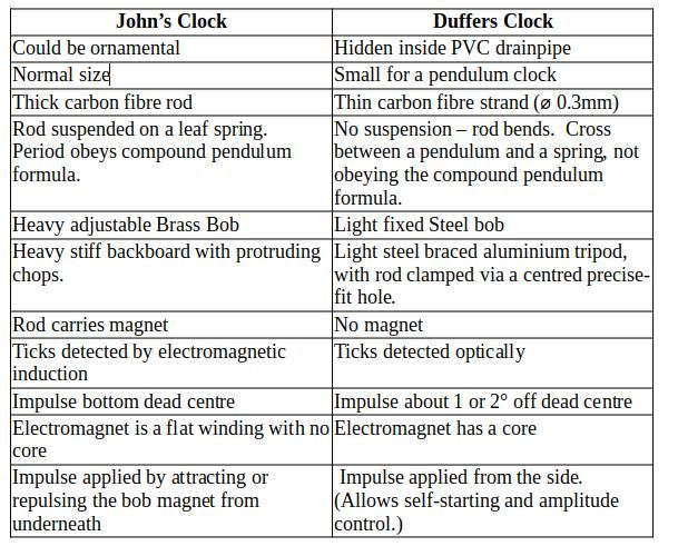
          May be of interest to compare my Arduino Pendulum with John's.

          differences.jpg

          John is more certain of success because his clock is based on best practice. Mine is experimental!

          Current status, it's being run by a Nucleo rather than an Arduino at the moment because the faster microcontroller has a resolution of about 1µS compared with 4µS. Still not good enough, I'm after 100nS or better.

          John brought my attention to the picPet, which uses a different technique to measure times. I'm trying to replicate the picPet method on an Arduino. Appears possible and Arduino should be capable of somewhat finer resolution than picPet because it use a faster clock. Few examples on the web so I've been forced to read Data Sheets and experiment. Have been getting reasonable approximations for some time but was baffled why they were erratic. Twigged last night I've been reading the wrong register, the one that carries on counting after the event, instead of the snapshot. Will modify the code and try again tomorrow.

          Dave

          #508185
          John Haine
          Participant
            @johnhaine32865

            Thanks Dave, a useful comparison. Nice to say "could be ornamental" – in the eye of the beholder I suspect! Actually the backboard has gone back underneath the bench so everything is supported by the brass channel pillars now. The bob is adjustable in principle, but the idea is for regulation to be digital by skipping a dial pulse every so often – at the moment every 132 cycles but that needs probably to be 133. The impulse is notionally at BDC but in fact is slightly later. The electromagnet is more solenoidal than flat – about 12mm dia and 16 mm long. I'm not sure the shape is optimal.

            Would be interesting to have an ArduinoPET! One would ideally need an external clock input so one could feed it 16 MHz from an OCXO or similar.

            #508202
            John Haine
            Participant
              @johnhaine32865

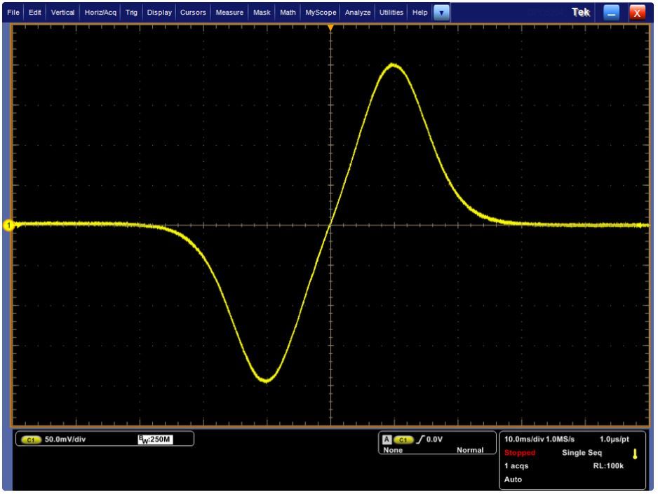
              Software is based on the very simple scheme I posted back on Dave's thread. The coil generates this sort of waveform as the magnet passes over it (not mine but from the web article with the simple software).

              waveform.jpg

              This applied to an Arduino analogue pin through a 220 ohm resistor and the Arduino samples this at about 2 kHz. During the first negative-going bit of course all the samples are zero. Just after the zero crossing when the voltage is changing quickest, when it reaches a sample value of "10" the analogue input is changed to a digital output and driven high for a period (10 ms currently). Current during this period is ~15 mA, with the 220R plus the 120R of the coil itself. The coil inductance is negligible so there are no time constant issues. At the end of the pulse the pin goes low and remains low (inhibiting sampling) for ~470 ms.

              There are 4 other software functions.

              • Every 2 pulses from the coil (i.e. every second) a 20 ms pulse is sent to the clock movement coil with a 270R resistor in series. This advances the movement by one tick.
              • Slight complication is that the current direction has to be reversed on alternate ticks so this takes 2 Arduino digital outputs.
              • The seconds pulsing function is inhibited for 1 s every "N" seconds to adjust the rate, the pendulum period being set slightly short. Currently N is 132 but needs some tweaking.
              • Finally the digital output from the Hall effect device, which goes low at the extreme pendulum swing if the amplitude exceeds a limit, raises an interrupt that inhibits impulsing (but not the other functions) for the next two centre crossings. When the clock settles down then roughly there are 7 swings or so without impulse followed by slightly fewer with.
              #508206
              duncan webster 1
              Participant
                @duncanwebster1

                I'm really enjoying this thread, John's clock is delightful, but using a quartz movement is cheating!

                The 'miss one every 132 cycles' works in principle, but gets a bit messy if you want to miss one every 132.3 cycles.

                When I eventually get round to revising my clock I'm going to

                1. establish the period of the pendulum by timing over 24 hours against the BBC time signal, say this comes to period = 500,010 us (assuming nominally 1/2 second pendulum)
                2. have the pendulum trigger an ISR which increments a variable pendulumCount += period
                3. have in the loop bit
                  if (pendulumCount > 1000000)
                  {pendulumCount -= 1000000;
                  step_ the_ slave();
                  }

                I think this keeps it within 1/2 second, adding or missing a pulse every now and again

                I like the double suspension, should keep it in a very straight line, could John tell us what length/width/thickness the shim is, and how wide spaced.

                As it is a long time since ME published anything about clocks I reckon Martin Evans should twist John and SOD's arms to do a write up.

                Edited By duncan webster on 18/11/2020 14:05:52

                #508223
                John Haine
                Participant
                  @johnhaine32865

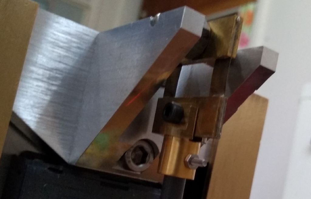
                  The active bit of the shims are 10mm long IIRC, 6mm wide, 0.1 mm BeCu sheet. I found a supplier some time back, after discussion with a sales guy he said it wasn't worth selling me any so he'd send a sample. I was expecting a couple of square inches, but he sent the end of a coil of 2" wide stuff with several metres on it! Shims are spaced 15mm apart, soldered between brass strips in a little soldering jig. Here's a rather poor photo of the top end of the pendulum.  Main benefit is the pendulum doesn't twist, but it can still swing back and forth on 2 pivots.

                  img_20201118_143314743.jpg

                  My scheme is already within +/1 0.5 seconds, but I agree it leaves a bit of error on the table unless you also trim the pendulum with a bit of weight. I am mulling over a more complex scheme that can be more accurate.

                  Edited By John Haine on 18/11/2020 14:43:40

                  #508227
                  John Haine
                  Participant
                    @johnhaine32865

                    As for the movement I was planning to make one but expediency won out over perfection. Anyway it would have been driven by a stepper motor, which I'd have to buy, so why not use an old movement which I've got? The hands are horrible, I need to make some better ones.

                    Every time I meet Martin at an exhibition he wants me to write up a clock – but I've made 2 since we last met…

                    #508241
                    Michael Gilligan
                    Participant
                      @michaelgilligan61133
                      Posted by duncan webster on 18/11/2020 14:04:47:

                      […]

                      When I eventually get round to revising my clock I'm going to

                      1. establish the period of the pendulum by timing over 24 hours against the BBC time signal,

                      .

                      I wouldn’t be too confident about the BBC time-signal, these days, Duncan

                      … especially if you are receiving it on DAB

                      MichaelG.

                      #508242
                      Michael Gilligan
                      Participant
                        @michaelgilligan61133

                        Nice write-up, John yes

                        MichaelG.

                        #508256
                        John Haine
                        Participant
                          @johnhaine32865

                          Thanks Michael. BTW, the little toggle switch below the dial, if "up" stops the movement which is convenient for setting.

                          #508323
                          duncan webster 1
                          Participant
                            @duncanwebster1
                            • Slight complication is that the current direction has to be reversed on alternate ticks so this takes 2 Arduino digital outputs.
                            • ……….

                            I got a quartz quartz movement going from an Arduino by having in series from the output a 470 ohm resistor, the clock movement, a 220uF cap to ground. The Arduino output is just toggled on/off with a 2 second cycle time (1 sec on, 1 sec off), but it only passes current whilst the cap is charging discharging. You don't need freewheel diodes as the current is zero at switch off. Depending on the actual movement you might need to fiddle with these values.

                            Very simple indeed, no H bridge and one output.

                            Edited By duncan webster on 18/11/2020 22:18:20

                            #508324
                            John Haine
                            Participant
                              @johnhaine32865

                              Thanks Duncan, I can see how that would work. But an extra capacitor! As you say, there's no shortage of pins. No h Bridge, just connected to two digital pins via a series resistor.  Normally both pins are LOW, they pulse alternately HIGH for 20 ms to advance the dial.  Mean current is about 0.2 mA. 

                              Edited By John Haine on 18/11/2020 22:23:53

                              #508350
                              duncan webster 1
                              Participant
                                @duncanwebster1

                                Why didn't I think of that? Even simpler

                                #508386
                                John Haine
                                Participant
                                  @johnhaine32865

                                  Not me, on the web in a design for a clock. Using a PIC I think – didn't even have the series resistor! But working on 3V supply.

                                  #508396
                                  John Haine
                                  Participant
                                    @johnhaine32865

                                    Average rate over the past 36 or so hours has been about 70 us/s (70e-5). Just adjusted the trim counted from 132 to 133 – theoretical value should be 133.26. (I think Duncan predicted that…)

                                    #510092
                                    Michael Gilligan
                                    Participant
                                      @michaelgilligan61133

                                      Another gem for pendulum enthusiasts

                                      … and it’s a free download: **LINK**

                                      An Account of Experiments for Determining the Length of the Pendulum Vibrating Seconds in the Latitude of London Author(s): Henry Kater

                                      MichaelG.

                                      .

                                      Ref. An Account of Experiments for Determining the Length of the Pendulum Vibrating Seconds in the Latitude of London Author(s): Henry Kater Source: Philosophical Transactions of the Royal Society of London, 1818, Vol. 108 (1818), pp. 33-102

                                      Edited By SillyOldDuffer on 06/12/2020 14:32:44

                                      #511656
                                      John Haine
                                      Participant
                                        @johnhaine32865

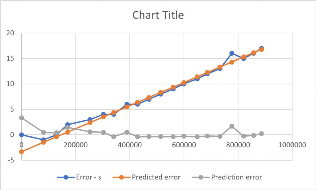
                                        Just an update after 10 days running.

                                        timekeeping_041220.jpg

                                        I've been taking twice-daily observations of the displayed time by taking a photo of the face, which my phone labels with its internal time that's locked to NTP (with a small error usually about 1.5 seconds lag). This is with the correction counter modulus set to 133 for a measured period (based on long term average) of 0.99246 seconds. The orange line is plotted from the calculated regression slope and gives a remaining rate of ~22 us / s which amounts to about 1.9 sec/day. Though the clock seems pretty stable obviously I don't want to be resetting the time every few days. I'm just about to upload new software that adds an extra counter to inhibit the correction every so often. So the main counter will omit a dial pulse every 132nd swing but every time the counter goes round 204 times it doesn't. So the 132 count will make the clock a little slow but every 204 x 132 = 26,928 seconds it'll effectively be advanced a second to make up. We'll see how this works!

                                        #511659
                                        Michael Gilligan
                                        Participant
                                          @michaelgilligan61133

                                          Looking good, John

                                          … any idea what caused those two anomalous bumps ?

                                          MichaelG.

                                          #511841
                                          John Haine
                                          Participant
                                            @johnhaine32865

                                            I've no idea Michael – of course if the rest of the numbers after ~5 days weren't so flat I wouldn't be surprised to see them! There is an inherent potential error in the reading process in that it involves taking a snapshot, which might be just as the second hand has moved; or just before it does; so that's +-1s. Then there's usually a small difference between "atomic" time (NTP) and phone system time which varies by a second or so. Put those together and you could easily account for +- 2s, but then the rest of the numbers look very stable!

                                            New software is now working, after a false start when I produced a new version with too many things "tidied up" that didn't work at all. So I went back to the previous working version and put in just the changes needed and it seems to be working OK now. I'll go back later and tidy things up. As always with clocks, time will tell!

                                            #511893
                                            Michael Gilligan
                                            Participant
                                              @michaelgilligan61133

                                              I can’t immediately think of a practical way of using this information, but you clever Arduino chaps might:

                                              Prime factors of 9192631770 = 2 × 3 × 3 × 5 × 7 × 7 × 47 × 44351

                                              MichaelG.

                                              #511944
                                              SillyOldDuffer
                                              Moderator
                                                @sillyoldduffer
                                                Posted by Michael Gilligan on 06/12/2020 00:37:51:

                                                I can’t immediately think of a practical way of using this information, but you clever Arduino chaps might:

                                                Prime factors of 9192631770 = 2 × 3 × 3 × 5 × 7 × 7 × 47 × 44351

                                                MichaelG.

                                                Yikes, 9192631770 had me going! Re-read the thread in case I'd missed something. Seemed familiar, but why? Got there in the end, but it took a lot longer than a second!

                                                Dave

                                                PS Although the earlier link to Captain Kater is broken, the paper is easily found by a search. Another interesting read: I don't know how you find this stuff. Thanks!

                                                #511957
                                                Michael Gilligan
                                                Participant
                                                  @michaelgilligan61133

                                                  Sorry the Kater link didn’t work for you, Dave … I believe that checked it when posting blush

                                                  The 9192631770 factors interested me because 44351 seems a manageable figure for what I might call a Tixel

                                                  If we are using a Caesium Clock as our ultimate reference, and using decimal arithmetic … I posit that calculations may somehow prove more convenient and less ‘noisy’ than attempting to work with microseconds or nanoseconds.

                                                  Way out of my depth … Which is why I just chucked it into the pot

                                                  MichaelG.

                                                  .

                                                  Edit: Looks like I must have linked the downloaded document instead of the referencing page blush

                                                  This should work : https://royalsocietypublishing.org/doi/10.1098/rstl.1818.0006

                                                  Edited By Michael Gilligan on 06/12/2020 12:31:41

                                                  #511985
                                                  SillyOldDuffer
                                                  Moderator
                                                    @sillyoldduffer
                                                    Posted by Michael Gilligan on 06/12/2020 12:24:50:

                                                    Sorry the Kater link didn’t work for you, Dave … I believe that checked it when posting blush

                                                    The 9192631770 factors interested me because 44351 seems a manageable figure for what I might call a Tixel

                                                    I've done what I should have done in the first place which is to fix the link using my moderator super-powers!

                                                    Tixel is genius. No instant use for 44351 but in my ongoing Arduino Pendulum project I have various base tick values; 156.25nS, 100nS, 62.5nS, and 50nS. In your honour I shall start calling them tixels! If we both try hard, we can get it into the OED.

                                                    Dave

                                                    #511995
                                                    Michael Gilligan
                                                    Participant
                                                      @michaelgilligan61133

                                                      yes laugh

                                                    Viewing 25 posts - 1 through 25 (of 63 total)
                                                    • Please log in to reply to this topic. Registering is free and easy using the links on the menu at the top of this page.

                                                    Advert

                                                    Latest Replies

                                                    Viewing 25 topics - 1 through 25 (of 25 total)
                                                    Viewing 25 topics - 1 through 25 (of 25 total)

                                                    View full reply list.

                                                    Advert

                                                    Newsletter Sign-up