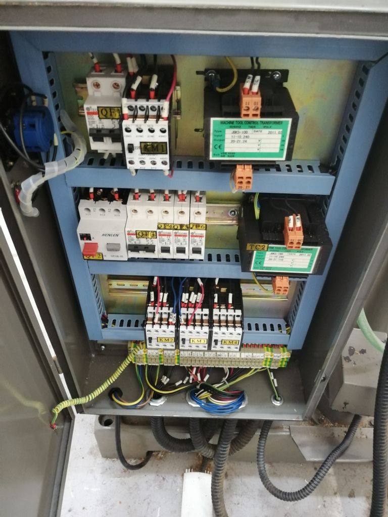
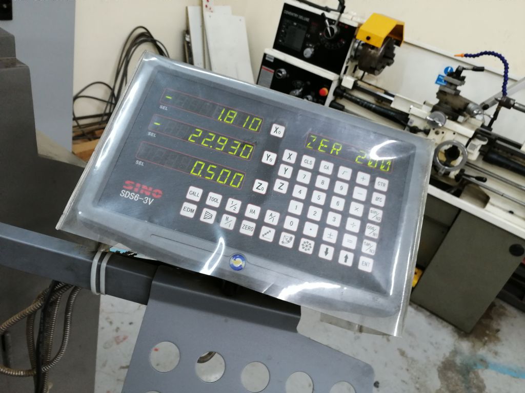
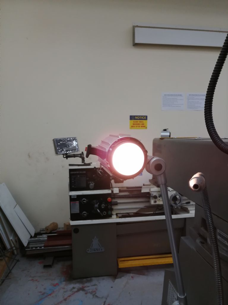
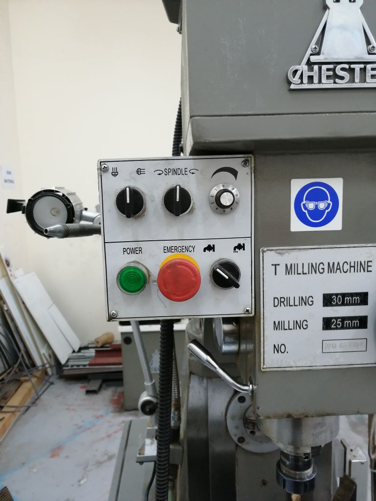
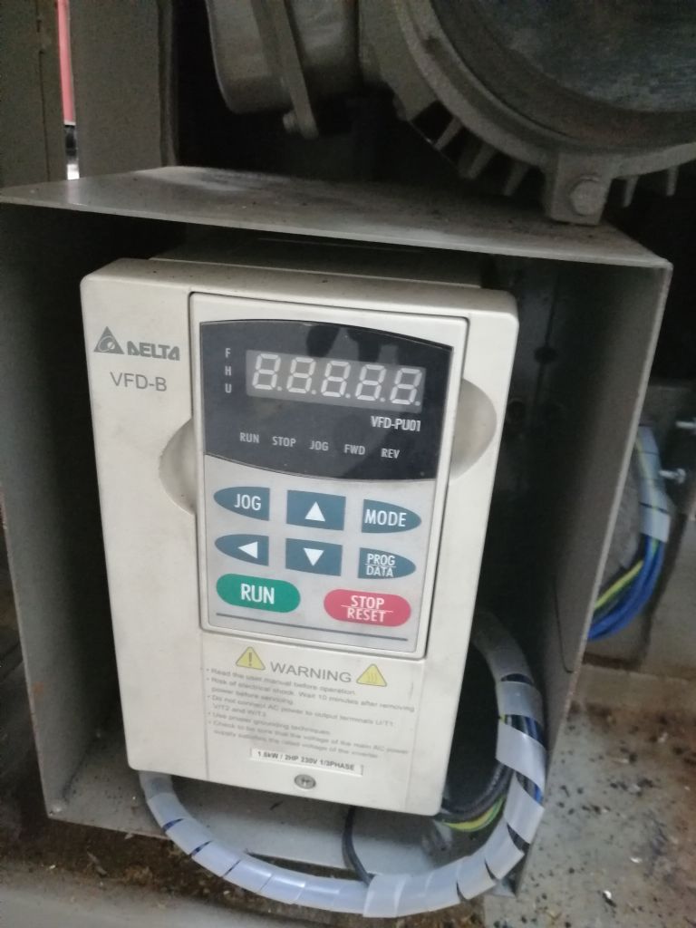
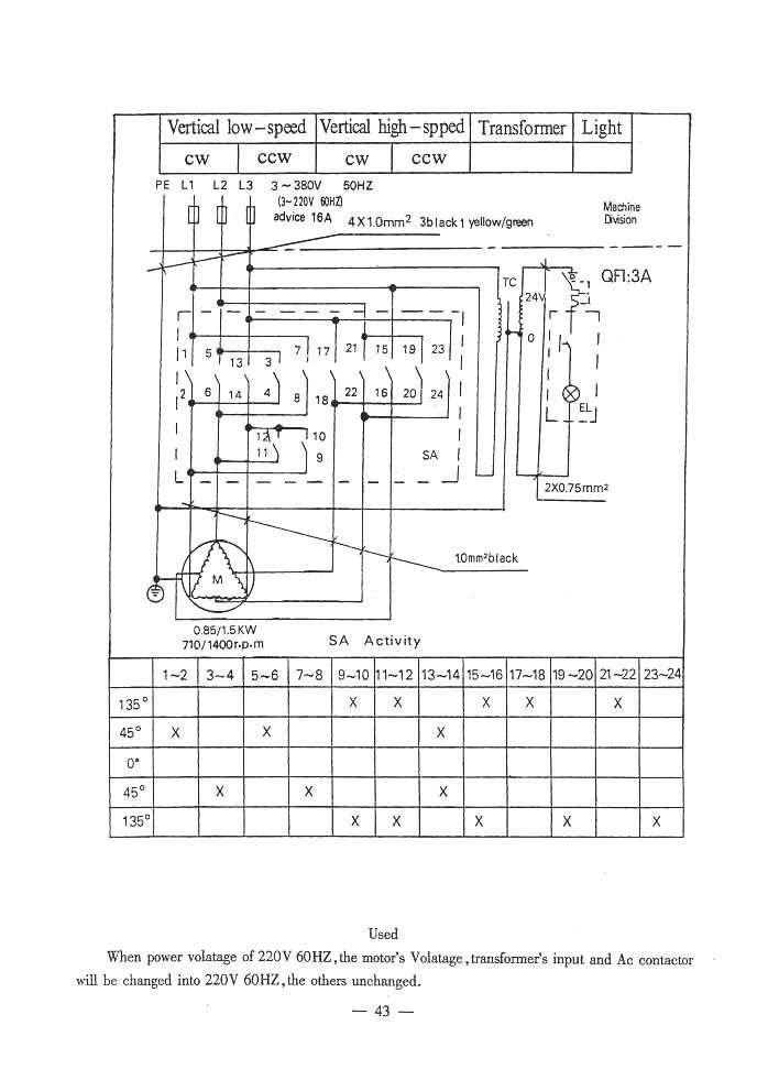
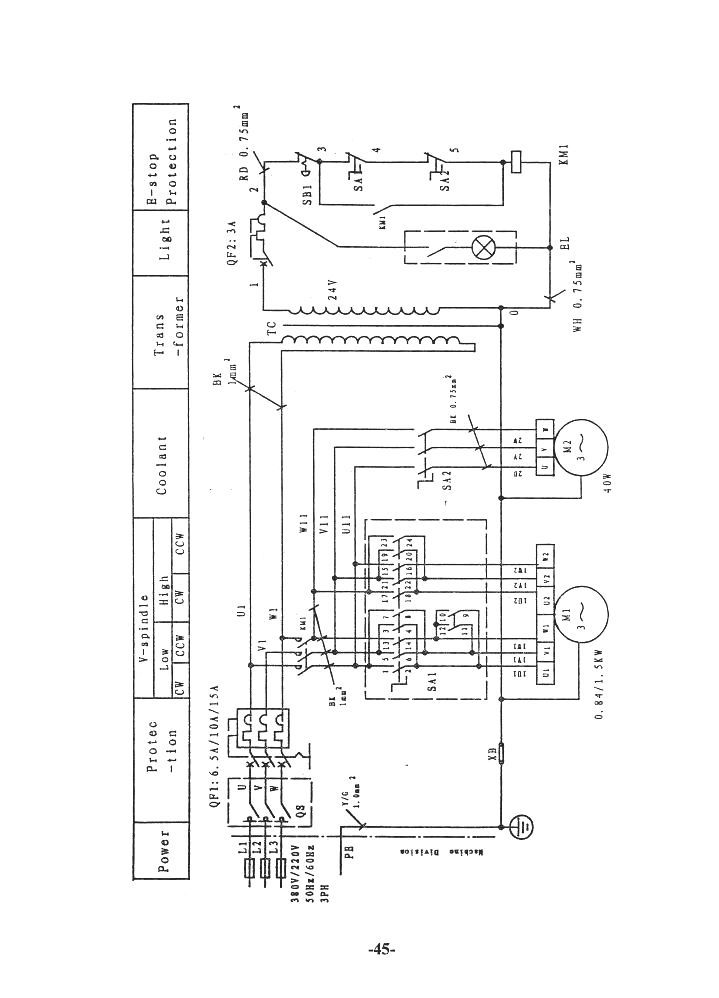
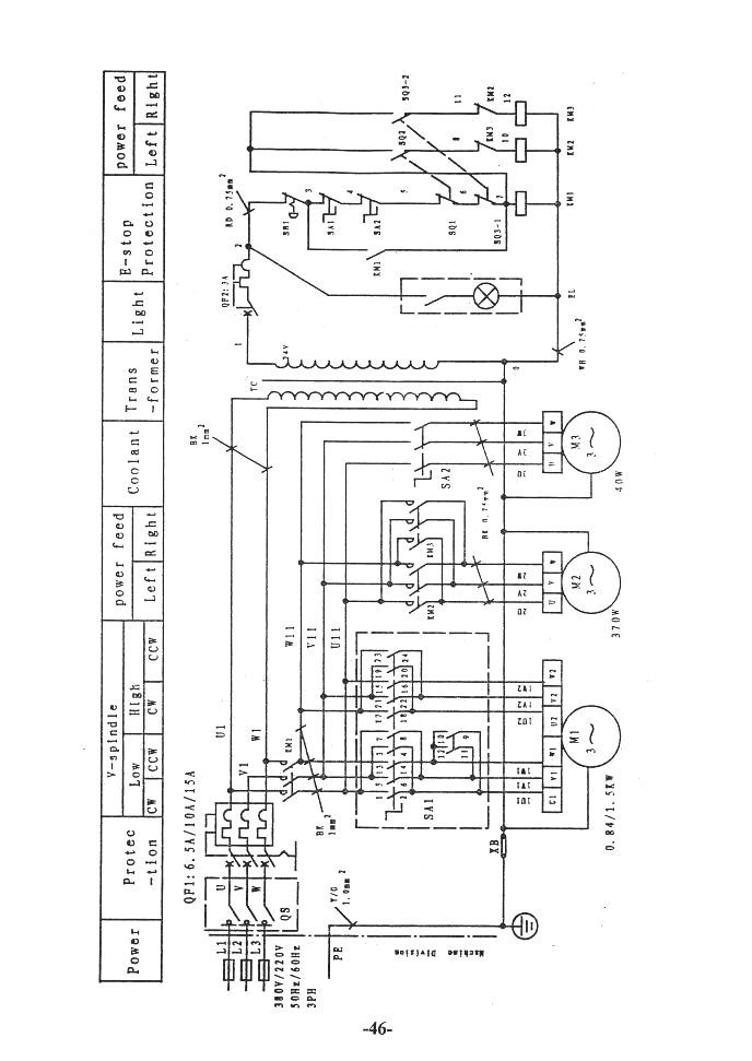
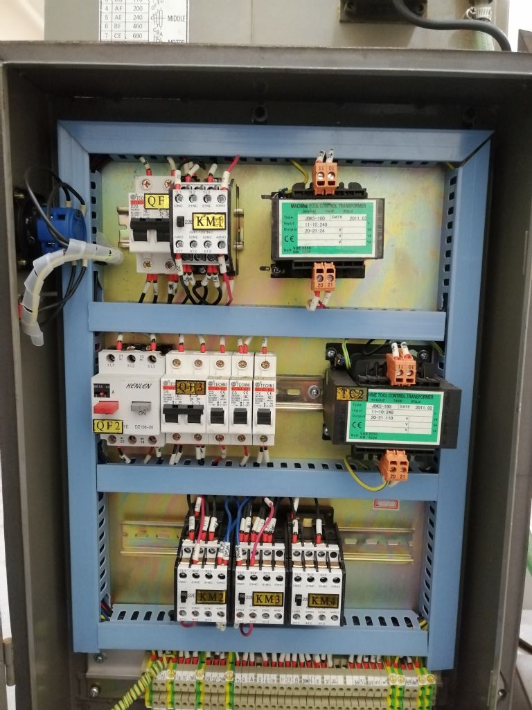
Universal T milling machine from Chester : Issue with Starting
Universal T milling machine from Chester : Issue with Starting
- This topic has 19 replies, 10 voices, and was last updated 10 July 2019 at 18:25 by
martin perman 1.
Viewing 20 posts - 1 through 20 (of 20 total)
Viewing 20 posts - 1 through 20 (of 20 total)
- Please log in to reply to this topic. Registering is free and easy using the links on the menu at the top of this page.
Latest Replies
Viewing 25 topics - 1 through 25 (of 25 total)
-
- Topic
- Voices
- Last Post
Viewing 25 topics - 1 through 25 (of 25 total)
Latest Issues
Newsletter Sign-up
Latest Replies


