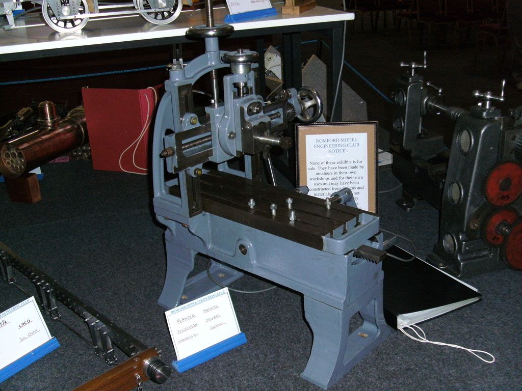
A shaping machine in epoxy concrete

Advert

A shaping machine in epoxy concrete

Home Forums Model Engineers’ Workshop. A shaping machine in epoxy concrete

Viewing 9 posts - 1 through 9 (of 9 total)
  • Author
    Posts
  • #70813
    Richard Parsons
    Participant
      @richardparsons61721

      I have always wanted to get my ‘hooks’ on a machine which would allow me to machine really flat surfaces. I designed a small knee-less horizontal milling machine which was to be fabricated from structural steel and would use SKF (usual disclaimer) linear slides. My local suppliers have minimum order rules which for the products I wanted. I would have had to buy 10 pairs of each size and length of rail and 20 pairs of each of the corresponding bearings. These would have cost a king’s ransom so that idea was binned. I have a rule never to publish anything I have not made and know works, so I kept very quiet about the thing.

      That is how things stayed until I found an article on the web entitled ‘A Small Shaping Machine by Mr E.H. Knight. It was published in the Model Engineer 5th October 1952. It was totally fabricated without welding or brazing. This article can be found here.

      I looked at the article and thought ‘this is a dead ringer’ for the epoxy concrete technique used by John McNamara the thread on this website called New Technology in the Model Engineers workshop

      The original specification by Mr E.H. Knight is as follows

      Table size 4 ¾” (120.65mm) by 4 ¼” (107.95mm)

      Stroke 3” (76.2mm)

      Cross feed 4” (101.6mm)

      Tool down feed movement ½” (12.7mm)

      Unfortunately he gives no direct indication of the maximum daylight that is from the bottom of the ram to the top of the base plate. From Mr. Knight’s drawings looks to be around 2” (50.8mm)

      All of Mr Knight’s slide ways are 60/30° mitres with no gib-strips.

      I think that the dimensions given are too small for my use. I want to build small ICs as I can get the full-ish kit of materials from the U.K.

      My specification would be

      Table size 8 ¾” (222.25mm) by 8” (203.2mm)

      Stroke 6” (152.0mm)

      Cross feed 6” (152.0mm) as measured from the centre of the ram

      Daylight 6” (152.0mm)

      Tool down feed movement minimum 2” (50.8mm)

      Since I am scaling Mr. Knight’s sized up by a half I am going to increase the thickness by 1.5 times. So a ¼” will become 3/8” and using John McNamara figures from his contribution in “New technology in Model Engineers Workshop” I will thicken the material by a factor of 4 where needed. This will be in the base thickness, the cross traverse and the ram carrier will be cast in epoxy concrete. The ram and clapper box assemblies will be in steel as will the top of the base plate.

      I want to power the machine as I have no liking to pull the ‘punishment leaver’ for several hours. I have a 1/8HP Squirrel Cage motor and would not like to take more than 40-60 thou (1-1.5mm) cuts. Mr Knight’s machine has no automatic cross feed, mine will have. This will be a ratchet wheel which turns the cross feed screw through a key-way. The feed pawl will be at the rear of the ram and will engage the ratchet on the return stroke. Its position on the ram will determine the amount of feed.

      The slide-ways, I have an idea about them which I will reveal later once I have sorted out a material.

      I would love to hear comments and helpful advice.

      Advert
      #38056
      Richard Parsons
      Participant
        @richardparsons61721

        The beginnings of an idea

        #70831
        John McNamara
        Participant
          @johnmcnamara74883
          Hi Richard


          Great Idea

          You can make the base and the raised section at the back that supports the X axis ways (in one piece if you like) in epoxy concrete and you are way. The T slotted table would be better in steel. The alternative being a grid array of cast in (to the base casting) threaded steel inserts. You sometimes see these on CNC mills instead of T slots.

          I would be happy to help in any way, PM me with your email if you like.

          Cheers

          John

          #70836
          Richard Parsons
          Participant
            @richardparsons61721

            Many thanks John. My idea for the table was to cast the base of the table in one with the cross traverse carrier and cast in the recesses for the ‘T’ nut slots. I was also going to cast in rows of threaded inserts (which would be tack welded to the Re-bar armature. The strips which form the table top ‘T’ slots would be ‘screwed and glued’ to act as a work surface. I do not actually use ‘T’ nuts I use a modified bolt. I standardise on 8mm for the Myford and 10mm for the mill although I often use 8mm on the mill as well.

            Most of the armature will be in 6mm re-bar tacked together. I will also have to build a jig to hold at least 3 datum inserts in a fixed position to each other to act as reference points.

            #70839
            dcosta
            Participant
              @dcosta

              Hello Richard.

              Have You considered to take a look at the Gingerys book “The metal shaper” ?

              I’ve been making a shaping machine and I am more or less following that book.

              If You want You can see some images of my work at http://www.model-engineer.co.uk/albums/member_album.asp?a=8270 and the first movie showing the shaping machine in motion at http://www.youtube.com/watch?v=qimqVphwS0c

              I think that the dimensions You want for the cross slide ways may be achieved. Mine has 265mm and the cross slide has 111mm. I wanted the cross slide ways to be a little longer but was limited by the table size of my milling machine.

              If You go the way of epoxy concrete and want the shapping machine to be motor powered, remember You need space inside the columns (side walls) to fit the scotch yoke and perhaps You also will need to machine some surfaces inside the columns to support the scotch yoke bosses.

              I’ve not yet cut metal with my shaping machine so I don’t yet have an opinion on the modifications I made to the Gingery’s original plans.

              Note: There’s a gentleman in Belgium who is building a shaping machine more or less following Gingery’s book with two main deviations. He is scaling its dimensions from one inch to one and half (If my memory serves me well…) and he is fabricating it from steel. If You want I may ask him to show You some pictures of his work.

              Best regards
              Dias Costa

              #70850
              KWIL
              Participant
                @kwil
                Richard,
                 
                Try Zapp Automation Ltd, Poole, (www.zappautomation.com), they will supply single bearings if you wish. Helpful (Usual disclaimer)
                #70852
                John McNamara
                Participant
                  @johnmcnamara74883

                  Hi Richard

                  A good source for new linear Bearings is EBay, there are a number of regular posters, yes mostly from China. Quite a few package set deals too; Ok there is the risk of “site unseen”, if you Google the name of a particular supplier you find you will often find commentary on various forums regarding the veracity of that supplier, (Most are fine they want repeat business). The prices are compelling. I am not referring to the second hand goods posts on EBay of which there are many.

                  Also from the US Google “VXB Bearings” well established and a great variety, I have no connection with them.

                  Re: T nuts, as you do I sometimes use a bolt instead of a T nut. However whenever I do I am very wary of the point load it places on the edges of the T slot. A T nut distributes the load along the slot for some distance, there is a lot less risk of breaking the cast iron slot, as often seen on secondhand machinery.

                  Cheers

                  John

                  #70868
                  Richard Parsons
                  Participant
                    @richardparsons61721

                    I would like to make a little point. I live in Hungary a place which has been nearly de-industrialised. Three or four years ago a number of ‘Oriental Gentlemen’ appeared in the country with suitcases of cash. If there is one thing a Hungarian cannot resist is a suitcase full of cash, especially if the only paperwork wanted is a ‘Chop’ against a weight in a book full of Chinese writing. The country was almost swept clean of anything metallic. It is still going on. If we have a good thunder storm and the power fails, everyone is watching their local overhead feeders to see they do not ‘vanish’. All you can get now is ‘structural section’ steel, which is all the ‘stock holders’ hold. If 75 to 80% of the bulk of my machine is this stuff it is well worth the trouble. I think there is a boat building outfit (in the middle of the great plains! ) who I am going visit to next week. All I want is an Epoxy supplier.

                    Bringing metal in from the U.K./Germay/Austria etc can be both risky (it tends not to arrive) and very is expensive. This is why I became very excited by the epoxy concrete. Ballast I can get from the dredgers on the Danube (often several tonnes for putting a ‘Crane Splice’ into the end of a mooring wire, or running a ‘long splice’ to salvage a thick rope some idiot has cut.

                    The smaller particles I can get from my Garden – I live in the ‘arany homok’ (the golden sands). This stuff is pre-mixed in particle size and the sun will dry it for me for free.

                    I have just done a particle size analysis and find that the minimum grain size is well over 30 minutes. The analysis is that done by telescope grinders for sizing their ‘Rouge’ polish. You need some clean old jam pots. You dump the raw powder into a jar, and mix it with water. Leave it for about 1 second and decant the water into a second jar without disturbing the sediment. Leave the second jar for 5 seconds and repeat the decanting into another jar. No 2 jar contains the 5 second particles. The process is repeated for lengthening intervals and each jar contains finer particles than the first.

                    I must thank Dias for his U-tube images. These lead me onto here. It shows a miniature Planer and I have found others a bit bigger like the one below. These seem to be about 80% cast iron.

                    I am now going to detail my slide ways for my next post which are much easier to make than describe or draw.

                    #610205
                    JasonB
                    Moderator
                      @jasonb

                      Recent post moved here

                    Viewing 9 posts - 1 through 9 (of 9 total)
                    • Please log in to reply to this topic. Registering is free and easy using the links on the menu at the top of this page.

                    Advert

                    Latest Replies

                    Viewing 25 topics - 1 through 25 (of 25 total)
                    Viewing 25 topics - 1 through 25 (of 25 total)

                    View full reply list.

                    Advert

                    Newsletter Sign-up