Posted by Andrew Johnston on 24/07/2020 09:29:32:
I expect 14.5° PA was originally chosen for convenience as sin(14.5) is 0.2504, which makes life easier when you don't have a calculator.
As Martin says there is a compromise between root thickness of the tooth and radial loads as the PA varies; think about the force vector.
However, there are also practical reasons. Larger values of PA reduce undercutting when hobbing gears. Undercutting further weakens the tooth. As an example multistart worms for power transmission may use a PA as high as 60° to avoid undercutting of the mating worm wheel.
Andrew
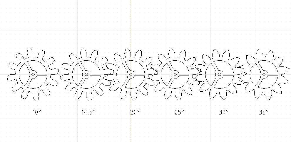
Building on Andrew's comments, a picture always helps!

Comparing the 10° and 35° gears, left and right, the 10° teeth are distinctly notchy whereas 35° teeth are obviously broad, and consequently much stronger, but difficult to mesh. Notchy gears transfer power more efficiently and put less force on bearings, but are weaker. The weakness of low pressure angle gears gets much worse as the number of teeth are reduced because the tooth has to be undercut to avoid interference.

Gear design is a compromise between power transmission efficiency, bearing force, strength, interference and manufacturing convenience. I find the geometry and maths challenging!
"The Theory of Machines, Bevan, London, 1950" says the 14.5° angle was decided in the USA by the Brown and Sharpe Manufacturing Company. It's a compromise. Not explained why B&S chose 14.5° rather than some other nearby angle, but it might be to do with the geometry of the underlying rack. The manufacturing accuracy of involute gears depends on the accuracy of the generating rack, so it may be to do with making accurate racks. However, B&S got it wrong! Although 14.5° is a good choice for many Victorian purposes, it's weak compared with 20° teeth, which replaced it at the time for stub teeth, and has been the preferred standard for many decades.
14.5 and 20° teeth are off the shelf gears. Other pressure angles available. A major advantage of Involute Gears is they aren't fussy about centres,. As nothing is ever easy, the pressure angles of involute gears must match. Although eye-ball similar, 14.5° and 20° gears can't be mixed – they interfere and grind.
Which to choose? In a new design, 20° every time. Building to a old plan calling for 14.5° gears, following the plan is likely to be less bother – apart from old gears gradually increasing in price why mess retrofitting a slightly different gear set? Replacing gears in old equipment, always use the right gear.
Dave
Peter Howell 1.


