Can Anyone Explain How This is Used?

Advert

Can Anyone Explain How This is Used?

Home Forums Model Engineer. Can Anyone Explain How This is Used?

Viewing 9 posts - 1 through 9 (of 9 total)
  • Author
    Posts
  • #329240
    SillyOldDuffer
    Moderator
      @sillyoldduffer

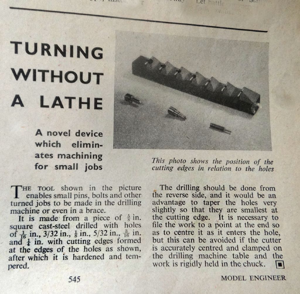
      This very short article appears in ME №2891 18 October 1956.

      odd_tool.jpg

      The photograph of the tool is blurred with poor contrast in the original.

      Does anyone know how the teeth should be shaped and how it works? I'm guessing this is so simple it's obvious. But not to me!

      Ta,

      Dave

      Advert
      #37750
      SillyOldDuffer
      Moderator
        @sillyoldduffer
        #329251
        ega
        Participant
          @ega

          Hard to see from the photo but the cutting action may be similar to that of those excellent chatter-free countersinks where the cutting edge is formed by the convergence of a hole at 45 deg to the tool's axis with the 90 deg, etc cone.

          Did you check subsequent ME Postbags to see if anyone wrote in about it?

          #329252
          Michael Gilligan
          Participant
            @michaelgilligan61133

            Dave,

            Mmm … Shame about the original image quality: I'm sure the devil is in the detail.

            In principle, I think it's best thought of as a set of single edge cutters in a row, one for each diameter.

            Material would be held in the rotating drill chuck and pushed through the tool.

            [ sorta like a lathe on 'relativity' ]

            A modern multi-tooth device, roughly equivalent in operation, is shown in this patent.

            **LINK**

            https://worldwide.espacenet.com/publicationDetails/originalDocument?CC=US&NR=2013279999A1&KC=A1&FT=D&ND=&date=20131024&DB=&locale=

            MichaelG.

            .

            Edit: ega has sussed the relevant geometry, I think.

            Edited By Michael Gilligan on 26/11/2017 16:52:31

            #329257
            Jeff Dayman
            Participant
              @jeffdayman43397

              I expect the stock would be turned by a drill or brace and introduced into the bore of the tool to cut. The tool was likely intended to be held in a vise.

              A neat idea, but tool life would likely be short cutting steel, brass probably would enable a long tool life. Not easy to resharpen the cutting edges I think, if the tool were hardened.

              #329279
              Neil Wyatt
              Moderator
                @neilwyatt

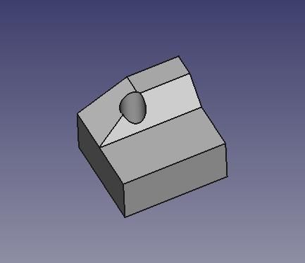
                I think each 'cutter' is shaped like a 'roof' aligned with each hole. Half of each side is then filed away again to create a pair of teeth on each hole.

                This would allow all the teeth to be created by filing alone:

                odd cutter.jpg

                EDIT: on staring at the original pic, I think each tooth is filed down slightly to reduce the front clearance and make the teeth stronger. This is where you would sharpen it.

                Edited By Neil Wyatt on 26/11/2017 19:26:40

                #329281
                Robbo
                Participant
                  @robbo

                  ega

                  I had a look at the "Postbag" and "Readers' Queries" in some later editions while digesting my tea, but there was no mention of the device.

                  Then I got bogged down in reading some of the letters. Its amazing how rude they were to each other in those days!

                  #329300
                  SillyOldDuffer
                  Moderator
                    @sillyoldduffer

                    Thanks Robbo for checking Postbag. I only have two mags from 1956. They were rude back then weren't they! And we only read what the editor was prepared to print!

                    Thanks for the other suggestions. Like Neil I've been trying to visualise the cutter in 3D CAD. My effort is much less convincing than his.

                    turn.jpg

                    Pity the photo is unclear. I don't think it's as complicated as Neil's suggestion but it's hard to tell.

                    Interesting that guys used tools like this. It's for chaps who couldn't afford a Super-Adept! Impressive what can be done with limited resources.

                    Dave

                    #329301
                    Bazyle
                    Participant
                      @bazyle

                      Have you ever made a 'spot face cutter'? Essentially a bit of silver steel, hole bored axially, saw across the end twice then file 4 angled lands on the end, insert an alignment dowel in the hole. If you leave out the dowel and spin it into some wood you have a 'plug cutter'. Well this si just a two land version for metal.

                      Google spot face cutter and plug cutter images if necessary.

                      Probably a good idea for non lathe owning model railway boys of the time who could make the gizmo in the school workshop.

                    Viewing 9 posts - 1 through 9 (of 9 total)
                    • Please log in to reply to this topic. Registering is free and easy using the links on the menu at the top of this page.

                    Advert

                    Latest Replies

                    Home Forums Model Engineer. Topics

                    Viewing 25 topics - 1 through 25 (of 25 total)
                    Viewing 25 topics - 1 through 25 (of 25 total)

                    View full reply list.

                    Advert

                    Newsletter Sign-up